Development of Data Acquisition and Control
Software for Neutron Radiography Facility at
Serpong, Indonesia
Bharoto*
Center for Technology of Nuclear Industry Materials, National Nuclear Energy Agency Puspiptek Area, Serpong, Tangerang 15314, Indonesia
A R T I C L E I N F O A B S T R A C T
Article history:
Received 16 January 2013
Received in revised form 20 August 2013 Accepted 23 August 2013
Keywords: Neutron Radiography Tomography Data Acquisition Control Software
A system for data acquisition and control software for the neutron radiography facility at Serpong has been developed. The software was developed to replace the previously existing control software which was no longer used due to problems on its computer hardware. Visual Basic running under Microsoft Windows operating system was used in developing the new software. In the hardware side, the film grabber and the motor driver were replaced. In the new system, the film grabber which was used to capture the image in the old system is replaced with a programmable CCD camera. The motor driver which was used to control the camera in two directions has been replaced with a four-direction motor driver. The software is capable of displaying the images in a real time mode and record the images in the hard disk of a personal computer. To obtain optimal image quality, the software processes the captured images by performing temperature adjustment, camera exposure time adjustment, and integration of the captured image in a certain frame numbers. The software is capable of taking a number of snapshots at a certain time interval. For neutron tomography purposes, the software takes the snapshots automatically at a sample position in line with the stepping movement of the rotating sample table. The snapshots were saved in a picture format and a numeric format for further processing. The software has been successfully tested for real time method and tomography reconstruction. The data captured by using this software has been verified using both commercial and in-house computed tomography software.
© 2013 Atom Indonesia. All rights reserved
INTRODUCTION∗
Neutron radiography is a nondestructive imaging technique which is capable of visualizing the internal structures of a sample. Both the technology of the equipment and the techniques of neutron radiography have steadily advanced [1-3].
In 1992, the writer was a part of a team commissioned by the National Nuclear Energy Agency of Indonesia (BATAN) to utilize several neutron beam instruments for materials science research. One of the instruments was a neutron radiography facility. This facility had been used for non destructive inspection of inactive bulk materials using a direct method. Besides using the film method, this facility was also equipped with an analog camera for a real time examination. Afterward, a tomography reconstruction technique was implemented in 1998. However, after several years, there were problems with the computer hardware; as a result, the inspections could not be
∗
Corresponding author.
E-mail address: [email protected]
done with either real-time method or tomography techniques. Since 2007, the control system of the facility has been upgraded, and the neutron radiography activities utilizing both real-time method and tomography techniques have been restarted. The radiography activities use a Charge Coupled Device (CCD) camera belonging to the Center for Accelerator and Materials Process Technology (PTAPB–BATAN), Yogyakarta [4]. In order to obtain a better image quality, a new CCD camera from Andor Technology has been used. Compared with the older camera, which has a resolution of 320 × 320 pixels, the new one has a higher resolution of 1024 × 1024 pixels with a pixel size of 13 × 13 μm [5].
facility in Serpong, as well as the development of the data acquisition and control software.
EXPERIMENTAL METHODS
Neutron radiography facility
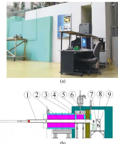
A neutron radiography facility has been completely installed at the S2 tangential beam port of the G. A. Siwabessy Multipurpose Reactor (RSG-GAS) , as shown in Fig. 1a. This facility consists of an inner collimator inside the RSG-GAS reactor wall, a 30 cm-diameter outer collimator, and two shutters, i.e. a main shutter driven by an electric motor, and an auxiliary shutter driven by a hydraulic pump. A movable sample table is located in front of a Li6-ZnS scintillation screen which visualizes the radiograph of the sample. In order to prevent damages by the neutron radiation to an ultra light-sensitive CCD camera, a TiO2 mirror with a 95% reflectivity is used to reflect the radiograph to the camera. Since light intensity of the radiography image emitted by the scintillation screen is very low, the scintillation screen, the mirror and the CCD camera are located inside the dark box, as shown in Fig. 1b. Then, the radiography image captured by the camera is further processed by a computer outside the radiography room.
(a)
(b)
Fig. 1. The neutron radiography facility at BATAN–Serpong.
(a) The photograph of neutron radiography facility, (b) A Schematic drawing of neutron radiography facility: 1. Inner collimator; 2. Outer collimator; 3. Main shutter; 4.Sample table; 5. Sample; 6. Auxiliary shutter; 7. Scintillate screen; 8. Mirror; 9. CCD camera.
Table 1 shows the instrumental parameters of the neutron radiography facility. After upgrading the facility, the radiography technique using Gd and X-ray film was still used to observe the material. A standard sample from American Society for Testing and Materials (ASTM) is also still used. Based on the radiography image of ASTM E-545 standard sample, the collimation system provides neutrons with the following composition and characteristics: the fraction of thermal neutrons: 60.95%, scattered neutrons: 0.78%, gamma: 0.48%, pair production: 2.85%, and the number of lines that could be seen: 4. From the measurement of the beam quality, the neutron radiography facility at BATAN Serpong was in the category of class III [5]. Although the facility is in the middle class of the category, many objects can be observed using this neutron radiography facility.
Table 1. Instrumental parameters of neutron radiography facility at BATAN
Neutron source
Neutron flux at sample position
Beam size at sample position Collimator L/D ratio Cadmium ratio converter, Li6-ZnS scintillate screen, Intensified CCD (ICCD) based imaging System[5,7].
The control system
In the old system, shown in Fig. 2a, the sample table was controlled by the computer through parallel port for rotary (ω) dan vertical (z) movement. Since the camera output was an analog signal a commercial TV Tuner Card was used. In the new system, shown in Fig. 2b, a programmable motor controller, mounted in the Peripheral Component Interconnect (PCI) slot, is used to position the sample table in four directions (ω, x, y, and z), and the analog camera was replaced with a programmable ICCD Camera equipped with a lens focus driver and a camera cooler. By adding two directions (x, y) in the sample table movement, the radiography object to be observed can be moved to the center of the camera viewer.
A type PMC-4B-PCI programmable motor controller from Autonics [6] capable of maintaining four axes simultaneously is used, while a type iKon-DD-934N-M BV camera from Andor Technology
which has a resolution with a number of 1024 × 1024 pixels with a size of 13 × 13
micrometers is used to replace the lower-resolution
old camera. The newer camera has a quantum efficiency (QE) of 95% for wavelengths of 350-800 nm. The electronic system of the CCD was
supported by a 16-bit digitizer capable of showing 65536 gray levels. The camera was equipped with a Peltier cooling device which is capable of cooling the CCD to -100oC. With this cooling system, the camera was able to suppress noise (dark current) to 0.00012 e/pix/sec [7].
(a)
(b)
Fig. 2. The schematic diagram of control system of the real time neutron radiography at BATAN–Serpong, (a) The old system and (b) The new system.
The data acquisition and control software
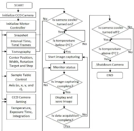
Along with hardware replacement for upgrading the facility, the data acquisition and control software has been modified to be more user-friendly. The software was written in the Visual Basic programming language. Figure 3 shows the flowchart of the software.
The software starts with initializing the camera, followed by initialization of the programmable motor controller. During the camera initialization, the software obtains the information of the camera parameters such as the detector format (1024×1024 pixels), A/D converter (2 channel), vertical pixel shift speed (44.975 μsec, it specifies the time taken to shift charge from one row on the CCD sensor to the next), and temperature range to which the detector can be cooled (-120oC to 20oC).
Fig. 3. The flowchart of the data acquisition and control software for neutron radiography facility.
During the initialization of the programmable motor controller, the software opens the controller card and writes the motion parameters to the card register address. The next step is showing the main window of the software. In the main window, there are many frames, i.e., title of the software, camera setting, sample table control, data acquisition for snapshot, data acquisition for tomography, data acquisition status, error message, real time control, and radiography image window. The data acquisition cannot be started unless the camera temperature has been set first by clicking the temperature display in the camera setting frame, and the camera has reached a temperature below 0oC. If the camera cooler is turned off, the software will inform the user by blinking the temperature display in red color, and marked with blue color if the camera temperature has reached the setting temperature. In the real time control frame, the software will show the radiography image in real time, record the dynamic image as a video file, or play the recorded video file according to the control button that was be clicked. When the software is showing the radiography image in real time, the user of the software can maintain the sample in four directions (ω, x, y, and z) through the sample table by clicking the button in the sample table control frame. When the start button in the snapshot frame is clicked, the software will save the radiography images with the setting interval time in graphic and numeric format file. For tomographic purposes, the software will collect the radiographic images for sample positions of 0o to 180o, in step sizes selected from 0.1o, 0.2o, 0.5o and 1.0o, and then save the data in both graphical and numerical format file.
Motor Driver (ω, Motor Controller
Sample Table Analog Camera
TV Tuner Card
TV Monitor
Motor Driver (ω, x, y, z)
Motor Controller
Sample Table Programmable ICCD Camera
Lens Focus Driver
Finally, the software could only be closed if the camera cooler is turned off and the camera has reached a temperature above 0oC.
RESULTS AND DISCUSSION
In the new system, the resolution of the radiography image has been increased by using a new camera, so that the internal structure of the object can be displayed more clearly. The position of the object to be observed can be moved to the center of the camera focus since the sample table can be adjusted in horizontal directions (x,y), and the data collection for tomography presents users with more choices of rotation step sizes, namely 0.1o, 0.2o, 0.5o and 1.0o.
Figure 4 shows a sequence of screenshots of the data acquisition and control software, resulting from an example operation. First, the user is informed that the softwareis initializing the devices, as shown in Fig. 4a. Then, Fig. 4b shows that the software notifies the user that the camera cooler is turned off, since the user tries to start data acquisition before setting the camera temperature. Figure 4c shows that the data acquisition and control software is collecting data for tomography, starting from the position of 0o to 180o with a step size of 1o, and showing the radiography image of the sample at position of 130o. This paper does not show the pictures of the software while running snapshot or
while controlling the sample table, since the data acquisition for tomography already shows both functions. Finally, Fig. 4c shows a notification to the user that the software cannot be closed unless the camera cooler is turned off first and the camera temperature has exceeded 0oC.
The software runs without any user intervention during radiography data collection.
Compared with previous ones, it is more user-friendly since the equipment status, such as the sample position, the camera temperature, and
image capturing process, is displayed in real time. With the previous system, the user had to move the sample table, capture the image and save the data manually.
In order to verify the results of this software, data from this software has been reconstructed using both in-house [8] and commercial [9] neutron computed tomography software such as Octopus 8.5. The reconstructed data was then displayed as 3D image using VG Studio 2.1. Verification results show that the data from the new software was able to be correctly reconstructed into images, both in 2D and 3D, as shown in Fig. 5. Additionally, various objects such as industrial devices (for instance, oil filter, automobile engine, two phase flow system), archeological artifacts (such as metal urns), and biological structures
(shell, sprouts root) have been tested using this software [5].
Fig. 4. The data acquisition and control software for neutron radiography facility at Serpong, Indonesia, (a) Initialization Window, (b) Warning notification if cooler was turned off when trying to start the data acquisition, (c) Main window during data acquisition for tomography, (d) Temperature warning when closing the software.
Fig. 5. The photograph of the sample and its 2D/3D tomography reconstruction using in-house and commercial software [8, 9].
98
(a)
(b)
CONCLUSION
A new data acquisition and control software has been developed. It is more user-friendly than the one previously used at BATAN. Commercial and in-house neutron computed tomography software verified that the data from the data
acquisition and control software was able to be reconstructed to both 2D and 3D images. The new software has been utilized in the neutron
radiography facility at Serpong, Indonesia for non-destructive testing of various objects such as industrial materials (oil filter, automobile engine,
two phase flow system), archeological artifacts (metal urns), and biological structures (shell, sprouts root).
ACKNOWLEDGMENT
This work was supported by BATAN under
the Neutron Beam Instruments Revitalization (in-house) project of 2009-2011. The author would like to thank Juliyani, Setiawan, and Fahrurrozi Akbar for help in collecting
radiography data and reconstructing the data into 3D tomograms.
REFERENCES
1. A.M. Shaikh, Pramana J. Phys. 71 (2008) 663. 2. M. Kureta, J. Power and Energy Systems 3
(2007) 211.
3. R. Yasuda, M. Nishi, M. Nakata and M. Matsubayashi, Development of advanced
neutron radiography for inspection on
irradiated fuels and materials; Feasibility study of neutron radiography in terms of PIE
execution, JAERI-Tech 2000-030 (2000). (in
Japanese)
4. Sutiarso, Bharoto, Setiawan and Juliyani,
Development of Neutron Radiography
Facility, RN1, for Tomography, Proceedings of
The 7th National Conference on Neutron and X-Ray Scattering (2009) 69.
5. Sutiarso, Bharoto, Setiawan, Juliyani and Fahrurrozi, Development of CCD Camera for Neutron Radiography Facility, RN1 in BATAN
Serpong, Proceedings of National Conference
on Human Resources of Nuclear Technology (2010) 439.
6. Anonymous, 4-Axis Motor Control IC MCX304 User’s Manual, Nova Electronics (2010).
7. Anonymous, Users Guide of iKon-M, and Software Development Kit, Andor Technology (2008).
8. Bharoto, Setiawan and Sutiarso, Software
Development of Neutron Tomography for
Neutron Radiography Facility at Serpong,
Proceedings of National Conference on Computation of Nuclear Science and Technology (2012)380.
9. Sutiarso, A. Fahrurrozi, Bharoto, Setiawan and Juliyani, 3D Neutron Tomography in RSG-GAS Reactor for Non-Destructive Inspections
of Industrial Components, Proceedings of
National Conference on Research and