GB Planer
Instruction manual
ID Mesin Serut
Petunjuk penggunaan
VI Máy bào bàn
Tài li u h
ng d n
TH
1
0037072
0037083
0045474
0037105
0037126
0037137
0037148
0037151
2
3
4
5
6
7
8
9
10
6
11
12
13
14
15
16
20
17
18
19
9
00371610
00371711
00446812
00446913
00371814
00447015
00447116
00447221
22
23
18
24
25
26
23
26
17
21
22
1mm (3/64”)23
22
24
A
B
27
22
24
28
22
11
24
18
26
21
17
17
00372218
00372319
00371920
00372021
00372122
00372429
30
31 19 2932
33
34
35
34
36
37
38
35
38
40
39
39
4123
00372524
00447725
00372826
00114527
00372928
00373029
00447842
43
44
0.1 mm - 0.3 mm45
46
47
48
49
27
50
51
24
52
ENGLISH
Explanation of general view
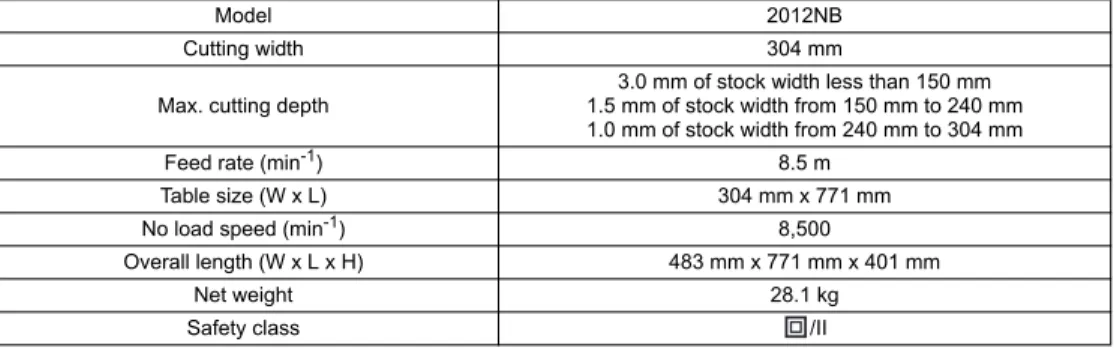
SPECIFICATIONS
• Due to our continuing programme of research and development, the specifications herein are subject to change without notice.
• Specifications may differ from country to country. • Weight according to EPTA-Procedure 01/2003
END201-5
Symbols
The following show the symbols used for the equipment. Be sure that you understand their meaning before use.
... Read instruction manual.
... DOUBLE INSULATION
ENE001-1
Intended use
The tool is intended for planing wood.
ENF002-1
Power supply
The tool should be connected only to a power supply of the same voltage as indicated on the nameplate, and can only be operated on single-phase AC supply. They are double-insulated in accordance with European Standard
and can, therefore, also be used from sockets without earth wire.
ENA001-2
SAFETY INSTRUCTIONS
WARNING! When using electric tools, basic safety precautions, including the following, should always be followed to reduce the risk of fire, electric shock and personal injury. Read all these instructions before operating this product and save these instructions.
For safe operations:
1. Keep work area clean.
Cluttered areas and benches invite injuries. 2. Consider work area environment.
Do not expose power tools to rain. Do not use power tools in damp or wet locations. Keep work area well lit. 1. Carrying handle 2. Sub-table 3. Bolt or screw 4. Pilot lamp 5. Switch lever 6. Crank handle 7. Scale 8. Indicator plate 9. Main frame 10. Depth gauge 11. Groove
12. Depth adjusting gauge 13. Stopper 14. Stopper button 15. Stopper knob 16. Table top 17. Lock plate 18. Drum 19. Thumb screw 20. Pulley
21. Blade installation bolt 22. Set plate 23. Magnetic holder 24. Blade 25. Claw 26. Socket wrench 27. Screw 28. Blade gauge 29. Hood 30. Hood holder 31. Chip cover 32. Rubber cap 33. Stay (B) 34. Stay (A) 35. Leg
36. Cap square neck bolt
37. Spring washer 38. Hex nut 39. Hex bolt 40. Flat washer 41. Bolt 42. Ruler 43. Post card 44. Adjusting screw 45. Hex wrench 46. Limit mark 47. Brush holder cap 48. Screwdriver 49. Column 50. Chain 51. Base 52. More than 4 mm Model 2012NB Cutting width 304 mm
Max. cutting depth 1.5 mm of stock width from 150 mm to 240 mm3.0 mm of stock width less than 150 mm 1.0 mm of stock width from 240 mm to 304 mm
Feed rate (min-1) 8.5 m
Table size (W x L) 304 mm x 771 mm
No load speed (min-1) 8,500
Overall length (W x L x H) 483 mm x 771 mm x 401 mm
Net weight 28.1 kg
Do not use power tools where there is risk to cause fire or explosion.
3. Guard against electric shock.
Avoid body contact with earthed or grounded surfaces (e.g. pipes, radiators, ranges, refrigerators). 4. Keep children away.
Do not let visitors touch the tool or extension cord. All visitors should be kept away from work area. 5. Store idle tools.
When not in use, tools should be stored in a dry, high or locked up place, out of reach of children. 6. Do not force the tool.
It will do the job better and safer at the rate for which it was intended.
7. Use the right tool.
Do not force small tools or attachments to do the job of a heavy duty tool. Do not use tools for purposes not intended; for example, do not use circular saws to cut tree limbs or logs.
8. Dress properly.
Do not wear loose clothing or jewellery, they can be caught in moving parts. Rubber gloves and non-skid footwear are recommended when working outdoors. Wear protecting hair covering to contain long hair. 9. Use safety glasses and hearing protection.
Also use face or dust mask if the cutting operation is dusty.
10. Connect dust extraction equipment. If devices are provided for the connection of dust extraction and collection facilities ensure these are connected and properly used.
11. Do not abuse the cord.
Never carry the tool by the cord or yank it to disconnect it from the socket. Keep the cord away from heat, oil and sharp edges.
12. Secure work.
Use clamps or a vice to hold the work. It is safer than using your hand and it frees both hands to operate the tool.
13. Do not overreach.
Keep proper footing and balance at all times. 14. Maintain tools with care.
Keep cutting tools sharp and clean for better and safer performance. Follow instructions for lubrication and changing accessories. Inspect tool cord periodically and if damaged have it repaired by an authorized service facility. Inspect extension cords periodically and replace, if damaged. Keep handles dry, clean and free from oil and grease.
15. Disconnect tools.
When not in use, before servicing and when changing accessories such as blades, bits and cutters. 16. Remove adjusting keys and wrenches.
Form the habit of checking to see that keys and adjusting wrenches are removed from the tool before turning it on.
17. Avoid unintentional starting.
Do not carry a plugged-in tool with a finger on the switch. Ensure switch is off when plugging in.
18. Use outdoor extension leads.
When tool is used outdoors, use only extension cords intended for outdoor use.
19. Stay alert.
Watch what you are doing. Use common sense. Do not operate tool when you are tired.
20. Check damaged parts.
Before further use of the tool, a guard or other part that is damaged should be carefully checked to determine that it will operate properly and perform its intended function. Check for alignment of moving parts, free running of moving parts, breakage of parts, mounting and any other conditions that may affect its operation. A guard or other part that is damaged should be properly repaired or replaced by an authorized service center unless otherwise indicated in this instruction manual. Have defective switches replaced by an authorized service facility. Do not use the tool if the switch does not turn it on and off. 21. Warning.
The use of any accessory or attachment, other than those recommended in this instruction manual or the catalog, may present a risk of personal injury. 22. Have your tool repaired by a qualified person.
This electric tool is in accordance with the relevant safety requirements. Repairs should only be carried out by qualified persons using original spare parts, otherwise this may result in considerable danger to the user.
GEB066-1
THICKNESSER SAFETY
WARNINGS
1. Wear eye protection.
2. Wear suitable personal protective equipment when necessary, such as hearing protection (ear plugs), respiratory protection (dust mask) and gloves when handling rough material.
3. Do not use the tool in the presence of flammable liquids or gases.
4. Make sure that all covers are installed in place before operation.
5. Handle the blades very carefully.
6. Check the blades carefully for cracks or damage before operation. Replace cracked or damaged blades immediately.
7. Tighten the blade installation bolts securely. 8. Remove nails and clean the workpiece before
cutting. Nail, sand or foreign matter can cause blade damage.
9. Do not remove chips from the chip chute when the motor is running. Clean out chips after the blades come to a complete stop. Always use a stick etc. when cleaning them out.
10. Do not leave the tool running.
11. Do not abuse cord. Never yank cord to disconnect it from the receptacle. Keep cord away from heat, oil, water and sharp edges.
12. The tool should only be used for wood and similar materials.
SAVE THESE INSTRUCTIONS.
WARNING:DO NOT let comfort or familiarity with product (gained from repeated use) replace strict adherence to safety rules for the subject product.
MISUSE or failure to follow the safety rules stated in this instruction manual may cause serious personal injury.
INSTALLATION
Movement and transport of planer (Fig. 1)
CAUTION:
• Watch your step when moving the tool.
Fold the sub-tables. Grasp the carrying handles when moving the tool.
When transporting it by vehicle, secure with a rope or other substantial means to prevent tipping or movement.
Positioning the planer (Fig. 2)
Locate the tool in a well lit and level place where you can maintain good footing and balance. Bolt/screw it to the workbench or stand (optional accessory) using the bolt holes provided in the base.
FUNCTIONAL DESCRIPTION
CAUTION:• Always be sure that the tool is switched off and unplugged before adjusting or checking function on the tool.
Switch action (Fig. 3)
CAUTION:
• Before plugging in the tool, always be sure that the tool is switched off. The pilot lamp lights up when the tool is plugged into the power source.
To start the tool, raise the switch lever. To stop it, lower the switch lever.
Dimensional adjustment (Fig. 4)
Lower the main frame by turning the crank handle counterclockwise until the indicator plate points to the scale graduation indicating the desired finished dimension. One full turn of the crank handle moves the main frame 2 mm up or down. The scale has inch graduations on its right side and metric graduations on its left side.
Adjusting depth of cut
The maximum depth of cut differs depending upon the width of workpiece being cut. Refer to the table. When you need to remove more than the amount specified in the table, set the depth of cut shallower than the amount and make two or more passes.
004465
To adjust the depth of cut, proceed as follows.
Insert the workpiece flat on the table top. Lower the main frame by turning the crank handle counterclockwise. The depth gauge will rise and the amount of gauge rise indicates the depth of cut. (Fig. 5)
CAUTION:
• Always lower the main frame when aligning the indicator plate with the graduation indicating the desired finished dimension. If you raise the main frame into the desired finished dimension, additional play in the screw may result. This may cause an undesired finished dimension.
• Always place the workpiece flat on the table top when predetermining the depth of cut. Otherwise, the predetermined depth of cut will differ from actual depth of cut.
Depth adjusting gauge (Fig. 6)
Use the depth adjusting gauge when you need to predetermine the depth of cut more accurately. To do so, proceed as follows.
1. First, plane the workpiece at the predetermined depth of cut. Measure the thickness of the planed piece to know how much more stock you need to remove. 2. Turn the depth adjusting gauge on the crank handle
until the 0 graduation is aligned with the groove on the tool.
3. Now turn the crank handle counterclockwise until the graduation for the desired depth of cut is aligned with the groove on the tool.
4. When you need to remove more than the amount specified in the table mentioned in the “Adjusting depth of cut” section, set the depth of cut shallower than the amount and make two or more passes.
Stopper (Fig. 7)
Use the stopper when you need to plane many workpieces to the same thickness. To do so, proceed as follows.
1. Turn the crank handle until the indicator plate points to the scale graduation indicating the desired finished dimension.
2. Depress the stopper button and lower the stopper until it just contacts the table top.
3. If you need fine adjustment of the stopper, turn the stopper knob.
CAUTION:
• When the stopper is not in use, always raise it to the topmost position. Never force the crank handle when the stopper is in contact with the table top. This may cause tool damage.
ASSEMBLY
CAUTION:• Always be sure that the tool is switched off and unplugged before carrying out any work on the tool.
Replacing planer blades
CAUTION:
• Handle the blades very carefully when removing or installing the blades to prevent cuts or injury from the
Width of workpiece being cut Maximum depth of cut Less than 150 mm 3.0 mm 150 mm - 240 mm 1.5 mm 240 mm - 304 mm 1.0 mm
blades and to prevent damage to the blades. They are razor-sharp.
• Clean out all chips, dust, pitch or foreign matter adhering to the drum or blades before installing the blades.
• Use blades of the same dimensions and weight, or drum oscillation/vibration will result, causing poor cutting action and eventually, tool breakdown. • Replace both blades at the same time.
• The disposable-type blade has a cutting edge on both sides. When one cutting edge becomes dull, you can use the other cutting edge. Always remove resin and dirt sticking to the reverse side of the blade before using the other cutting edge. This blade must not be re-sharpened. When both cutting edges become dull, the blade should be carefully thrown away.
1. Removing blades
Loosen the thumb screw which secures the chip cover and remove the chip cover. Remove the screws which secure the right side cover. Then remove the right side cover. Turn the pulley until the drum can be locked in the position whereby the blade installation bolts face upward. (Fig. 8)
For throw away blades only
Place the two magnetic holders on the set plate and push them in the direction of the arrow until the claw contact the blade. Remove the six blade installation bolts using the socket wrench. Grip the magnetic holders and raise them straight up to remove the set plate and the blade from the drum. Press the lock plate and turn the pulley 180° to lock the drum. Remove the other blade as described above. (Fig. 9 & Fig. 10)
For standard blades only
Remove the six installation bolts using the socket wrench. Raise the set plate and blade straight up to remove them from the drum. Press the lock plate and rotate the drum by turning the pulley 180° to lock the drum. Remove the other blade as described above. Remove the set plate from the blade. (Fig. 11 & Fig. 12)
2. Installing blades CAUTION:
• Use only Makita socket wrench provided to tighten the blade installation bolts. The use of any other socket wrench may cause overtightening or insufficient tightening of the bolts, resulting in severe injury. For throw away blades only
Provide a flat wood block approximately 300 mm long and 100 mm wide. Place the blade and the set plate on the wood block so that the blade locating lug of the set plate rests in the groove of the blade. Adjust the set plate so that both ends of the blade protrude approximately 1 mm beyond the end of the set plate. Place the two magnetic holders on the set plate and push them until the claw contacts the blade. (Fig. 13)
Grip the magnetic holder and slip the heel of the set plate into the groove in the drum. Install the blade installation bolts. (Fig. 9)
After tightening all the blade installation bolts lightly and evenly from the center to the outside, tighten them completely following the same sequence. Remove the magnetic holders from the set plate. (Fig. 10)
Install the other blade as described above. Rotate the drum slowly while pressing the lock plate to make sure there is nothing abnormal. Then install the chip cover and the side cover.
CAUTION:
• Do not tighten the blade installation bolts without the blade locating lug of the set plate correctly resting in the groove of the blade. This may cause damage to the blade and potential injury to the operator.
• Do not turn the tool on with the chip cover removed. For standard blades only
Place the blade on the blade gauge so that the blade edge is perfectly flush with the inside of the front rib (A). Place the set plate on the blade, then gently press the heel of the set plate flush with the back side of the blade gauge (B). Tighten the screws to secure the set plate to the blade. (Fig. 14)
Slip the heel of the set plate into the groove in the drum. Install the blade installation bolts. (Fig. 15)
After tightening all the blade installation bolts tightly and evenly from the center to the outside, tighten them completely following the same sequence. (Fig. 16) Install the other blade as described as above. Rotate the drum slowly while pressing the lock plate to make sure there is nothing abnormal. Then install the chip cover and the side cover.
CAUTION:
• Tighten the blade installation bolts securely when installing the blades.
• Do not turn the tool on with the chip cover open.
Changing type of blade
This tool can accept either throw away blades or standard blades. If you wish to change the type of blade, buy and use the following parts.
006417
Hood set (optional accessory)
When you wish to maintain clean operations through easy dust collection, connect the vacuum cleaner to the planer using this hood. Attach the hood holder to the hood and secure with the screws. (Fig. 17)
Loosen the thumb screws which secure the chip cover. Attach the hood to the planer and secure the chip cover and the hood together by tightening the thumb screws. (Fig. 18)
Planer stand (optional accessory)
Place the stays on a level location and assemble the legs inside. Secure with the cap square neck bolts, spring washers and hex nuts, then attach the rubber caps to the ends of the legs. (Fig. 19)
Now set the planer on the top of the assembled stand and secure with the four hex bolts, flat washers and hex nuts. (Fig. 20)
Changing from standard blade to throw-away blade
Changing from throw-away blade to standard blade Set plate --- 2 pcs.
Throw-away blade
(306 mm) --- 2 pcs. Magnetic holder--- 2 pcs.
Set plate--- 2 pcs. Pan head screw
M 4 x 6--- 4 pcs. Standard blade --- 2 pcs. Blade gauge---1 pc.
NOTE:
• Insert the hex bolts through the holes from the reverse side of the stand and secure them with the flat washers and hex nuts. If you insert the hex bolts from above the planer base, the hex bolts cannot be firmly secured. The planer stand should be bolted with the four bolts to the floor using the bolt holes provided in the legs. (Fig. 21)
OPERATION
CAUTION:
• Two or more pieces of narrow but similar thickness stock can be passed through the planer side by side. However, allow some spacing between the stock to permit the feed rollers to grip the thinnest piece of stock. Otherwise, a slightly thinner piece could be kicked back by the cutterhead.
Place the workpiece flat on the table top. (Fig. 22) Determine the depth of cut as described before. Switch on the tool and wait until the blades attain full speed. The workpiece should not be in contact with the feed roller when you turn the tool on.
Then insert the workpiece flush with the table top. When cutting a long or heavy workpiece, lift up its end slightly at the start and the end of the cut to avoid gouging or snipping at the extreme ends of the workpiece. (Fig. 23)
The use of the tool top enables quick, effortless return of the workpiece to the infeed table side. This is especially convenient with two operators.
CAUTION:
• The workpiece with the following dimensions cannot be fed into the tool because the interval between two feed rollers is 129 mm. Do not try to cut them.
004476
CAUTION:
• Stop the tool when the workpiece has stalled. Allowing the tool to run with a stalled workpiece causes rapid wearing of the feed rollers.
MAINTENANCE
CAUTION:• Always be sure that the tool is switched off and unplugged before attempting to perform inspection or maintenance.
• Never use gasoline, benzine, thinner, alcohol or the like. Discoloration, deformation or cracks may result.
Adjusting height of sub-table
The height of sub-table is factory-adjusted. If further adjustment is necessary, proceed as follows.
Place a postcard on the table and also place a ruler on the postcard. Turn the adjusting screw with the hex wrench
until the end of the sub-table contacts the ruler. Now the end of the sub-table is from 0.1 mm to 0.3 mm above the table surface. (Fig. 24 & Fig. 25)
Replacing carbon brushes
Remove and check the carbon brushes regularly. Replace when they wear down to the limit mark. Keep the carbon brushes clean and free to slip in the holders. Both carbon brushes should be replaced at the same time. Use only identical carbon brushes. (Fig. 26)
Use a screwdriver to remove the brush holder caps. Take out the worn carbon brushes, insert the new ones and secure the brush holder caps. (Fig. 27)
Keeping planer blades sharp
Dull blades can cause rough finish, an overload of the motor and dangerous kickback of the workpiece. Replace dull blades immediately.
Lubrication (Fig. 28)
Oil the chain (after removing the side cover R), the four columns and the screws for elevating the main frame. This periodic lubrication should be performed with machine oil.
CAUTION:
• Oiling and all maintenance should be done with the tool turned off and unplugged.
Cleaning
Always brush off dirt, chips and foreign matter adhering to the roller surfaces, motor vents and drums.
Limit for re-sharpening of standard blade
(Fig. 29)
Do not use the standard blade whose blade length is under 4 mm.
To maintain product SAFETY and RELIABILITY, repairs, any other maintenance or adjustment should be performed by Makita Authorized Service Centers, always using Makita replacement parts.
OPTIONAL ACCESSORIES
CAUTION:• These accessories or attachments are recommended for use with your Makita tool specified in this manual. The use of any other accessories or attachments might present a risk of injury to persons. Only use accessory or attachment for its stated purpose.
If you need any assistance for more details regarding these accessories, ask your local Makita Service Center. • Magnetic holder • Throw-away blade • Standard blade • Blade gauge • Socket wrench 9 • Hex wrench 2.5 • Hood set • Stand NOTE:
• Some items in the list may be included in the tool package as standard accessories. They may differ from country to country.
1 Less than 130 mm long
2 Having a groove more than 130 mm wide
3 Having grooves at intervals of 130 mm wide
Less than 130 mm
More than 130 mm
BAHASA INDONESIA
Penjelasan tampilan keseluruhan
SPESIFIKASI
• Karena kesinambungan program penelitian dan pengembangan kami, spesifikasi yang disebutkan di sini dapat berubah tanpa pemberitahuan.
• Spesifikasi dapat berbeda dari satu negara ke negara lainnya. • Berat menurut Prosedur EPTA 01/2003
END201-5
Simbol
Berikut ini adalah simbol-simbol yang digunakan pada peralatan ini.
Pastikan Anda mengerti makna masing-masing simbol sebelum menggunakan alat.
... Baca petunjuk penggunaan.
... ISOLASI GANDA
ENE001-1
Penggunaan
Mesin ini digunakan untuk menyerut kayu.
ENF002-1
Pasokan daya
Mesin harus terhubung dengan pasokan daya listrik yang bervoltase sama dengan yang tertera pada pelat nama, dan hanya dapat dijalankan dengan listrik AC fase tunggal. Mesin diisolasi ganda sesuai Standard Eropa dan oleh sebab itu dapat dihubungkan dengan soket tanpa arde.
ENA001-2
PETUNJUK KESELAMATAN
PERINGATAN! Saat menggunakan mesin-mesin listrik, tindakan kewaspadaan keselamatan dasar yang meliputi hal-hal berikut ini, harus selalu dipatuhi untuk mengurangi risiko kebakaran, sengatan listrik dan cedera. Baca semua petunjuk ini sebelum menggunakan mesin dan simpanlah petunjuk ini. 1. Pegangan jinjing2. Meja mesin 3. Baut atau sekrup
4. Lampu pengarah 5. Tuas saklar 6. Pegangan engkol 7. Skala 8. Pelat indikator 9. Rangka utama 10. Pengukur kedalaman 11. Alur
12. Pengukur penyetelan kedalaman 13. Penahan
14. Tombol penahan 15. Knop penahan 16. Bagian atas meja 17. Pelat kunci 18. Teromol
19. Sekrup putar 20. Puli
21. Baut-baut pengikat mata pisau 22. Pelat pengatur 23. Penahan magnetik 24. Mata pisau 25. Penjepit 26. Kunci sok 27. Sekrup
28. Pengukur mata pisau 29. Tudung
30. Penahan tudung 31. Tutup serpihan kayu 32. Tutup karet 33. Penopang (B) 34. Penopang (A) 35. Kaki
36. Baut leher persegi bertutup
37. Cincin pegas 38. Mur segi-enam 39. Baut kepala segi-enam 40. Ring plat 41. Baut 42. Mistar 43. Kertas karton 44. Sekrup penyetel 45. Kunci L 46. Tanda batas 47. Tutup tempat sikat 48. Obeng 49. Tiang 50. Rantai 51. Dudukan 52. Lebih dari 4 mm Model 2012NB Lebar pemotongan 304 mm
Kedalaman pemotongan maks. 1,5 mm untuk lebar kayu mulai dari 150 mm sampai 240 mm3,0 mm untuk lebar kayu kurang dari 150 mm 1,0 mm untuk lebar kayu mulai dari 240 mm sampai 304 mm
Laju pemakanan (min-1) 8,5 m
Ukuran meja (L x P) 304 mm x 771 mm
Kecepatan tanpa beban (min-1) 8.500
Panjang keseluruhan (L x P x T) 483 mm x 771 mm x 401 mm
Berat bersih 28,1 kg
Agar aman penggunaannya:
1. Jaga agar tempat kerja selalu bersih.
Tempat dan meja kerja yang berantakan mengundang kecelakaan.
2. Perhatikan lingkungan tempat kerja.
Jangan membiarkan mesin listrik kehujanan. Jangan gunakan mesin listrik di lokasi yang lembap dan basah. Jaga tempat kerja agar berpenerangan cukup. Jangan gunakan mesin listrik bila terdapat risiko penyebab kebakaran dan terjadinya ledakan. 3. Pelindung terhadap sengatan listrik.
Hindari sentuhan tubuh dengan permukaan berarde atau yang dibumikan (misalnya pipa, radiator, kompor, kulkas).
4. Jauhkan anak-anak dari tempat kerja.
Jangan biarkan orang yang berkunjung menyentuh mesin atau kabel ekstensi. Semua orang yang berkunjung harus dijauhkan dari tempat kerja. 5. Simpan mesin saat tidak digunakan.
Saat tidak digunakan, mesin harus disimpan di tempat yang kering, tinggi atau terkunci, jauh dari jangkauan anak-anak.
6. Jangan memaksa mesin listrik.
Mesin akan lebih baik dan lebih aman digunakan jika sesuai tingkat kegunaannya.
7. Gunakan mesin yang tepat.
Jangan memaksa mesin atau perangkat tambahan yang kecil untuk digunakan dalam pekerjaan yang berat. Jangan gunakan mesin untuk tujuan yang tidak sesuai kegunaannya; sebagai contoh: menggunakan gergaji sirkular untuk memotong cabang atau batang pohon.
8. Kenakan pakaian dengan baik.
Jangan memakai pakaian yang kedodoran atau perhiasan, karena bisa terbawa oleh bagian yang berputar. Dainjurkan untuk menggunakan sarung tangan karet atau sepatu anti-selip saat bekerja di luar ruangan. Kenakan penutup rambut untuk melindungi rambut yang panjang.
9. Gunakan kaca mata pengaman dan pelindung telinga.
Selalu kenakan pelindung muka atau masker debu jika operasi pemotongannya berdebu.
10. Hubungkan peralatan pengumpul debu. Jika tersedia fasilitas untuk menghisap dan mengumpulkan debu, pastikan fasilitas tersebut terhubung ke listrik dan digunakan dengan baik. 11. Jangan menyalahgunakan kabel.
Jangan sekali-kali membawa mesin dengan memegang kabelnya atau menarik kabel untuk melepasnya dari soket. Jauhkan kabel dari panas, minyak dan tepian tajam.
12. Bekerja yang aman.
Gunakan penjepit atau ragum untuk menahan benda kerja. Hal tersebut lebih aman dibanding
menggunakan tangan Anda dan membebaskan kedua tangan untuk menjalankan mesin.
13. Jangan meraih terlalu jauh.
Jagalah pijakan dan keseimbangan sepanjang waktu.
14. Rawatlah mesin dengan baik.
Jaga agar mesin pemotong tetap tajam dan bersih untuk mendapatkan kinerja yang lebih baik dan aman. Patuhi petunjuk pelumasan dan penggantian aksesori. Periksa kabel mesin secara berkala dan jika rusak perbaiki oleh fasilitas layanan resmi. Periksa kabel ekstensi secara berkala dan ganti jika rusak. Jagalah agar gagang kering, bersih, dan bebas dari minyak dan gemuk.
15. Cabut steker mesin.
Saat tidak digunakan, sebelum memperbaiki atau saat mengganti aksesori seperti mata pisau, mata mesin dan alat potong.
16. Lepas kunci penyetel dan kunci pas.
Biasakan untuk memeriksa apakah kunci dan kunci pas penyetel dilepas dari mesin sebelum menyalakannya.
17. Hindari penyalaan yang tidak disengaja. Jangan membawa mesin dengan posisi jari berada pada saklarnya. Pastikan saklar dalam kondisi mati saat memasukkan steker.
18. Gunakan kabel ekstensi untuk luar ruangan. Saat mesin digunakan di luar ruangan, gunakan hanya kabel ekstensi untuk penggunaan luar ruangan. 19. Jaga kewaspadaan.
Perhatikan pekerjaan Anda. Gunakan akal sehat. Jangan menggunakan mesin saat Anda lelah. 20. Periksa bagian yang rusak.
Sebelum terus menggunakan mesin, pelindung dan bagian lainnya yang rusak harus diperiksa secara cermat untuk menentukan apakah mesin akan bekerja dengan baik dan berfungsi sesuai yang diharapkan. Periksa kesejajaran bagian yang berputar, bebasnya gerakan bagian yang berputar, kerusakan komponen, kondisi pemasangan dan lainnya yang bisa mempengaruhi kerja mesin. Pelindung atau bagian lain yang rusak harus diperbaiki dengan tepat atau diganti oleh pusat layanan resmi kecuali jika ditunjukkan dalam petunjuk penggunaan ini. Ganti saklar-saklar yang rusak oleh fasilitas layanan resmi. Jangan gunakan mesin jika saklar tidak dapat menyalakan dan mematikan mesin. 21. Peringatan.
Penggunaan aksesori atau perangkat tambahan apapun, selain yang dianjurkan dalam petunjuk penggunaan ini atau dalam katalog, bisa menimbulkan risiko cedera.
22. Perbaiki mesin Anda oleh orang yang berkualifikasi.
Mesin listrik ini telah sesuai persyaratan keselamatan yang terkait. Perbaikan harus dilakukan hanya oleh orang yang berkualifikasi dengan menggunakan suku cadang asli, bila tidak, akan mengakibatkan bahaya yang cukup besar bagi pengguna.
GEB066-1
PERINGATAN KESELAMATAN
MESIN KETAM PENEBAL
1. Gunakan pelindung mata.2. Kenakan alat pelindung diri yang sesuai jika perlu, seperti pelindung telinga (sumbat telinga), alat pelindung pernafasan (masker debu) dan sarung tangan saat memegang bahan yang kasar. 3. Jangan menggunakan mesin jika ada cairan atau
gas yang mudah menyala.
4. Pastikan semua penutup terpasang pada tempatnya sebelum penggunaan.
5. Tangani mata pisau dengan sangat hati-hati. 6. Periksa mata pisau secara seksama akan adanya
keretakan atau kerusakan sebelum penggunaan. Segera ganti mata pisau yang retak atau rusak. 7. Kencangkan baut-baut pengikat mata pisau
kuat-kuat.
8. Buang paku dan bersihkan benda kerja sebelum memotong. Paku, pasir dan benda asing bisa menyebabkan kerusakan mata pisau. 9. Jangan membuang serpihan kayu dari saluran
pembuangan serpihan kayu saat motor bekerja. Bersihkan serpihan kayu setelah mata pisau benar-benar berhenti. Selalu gunakan stik dsb. saat membersihkannya.
10. Jangan tinggalkan mesin dalam keadaan hidup. 11. Jangan menyalahgunakan kabel. Jangan sekali-kali menarik kabel untuk mencabutnya dari stop kontak. Jauhkan kabel dari panas, minyak, air dan tepian tajam.
12. Mesin ini digunakan hanya untuk kayu dan bahan-bahan yang serupa.
SIMPAN PETUNJUK INI.
PERINGATAN:JANGAN biarkan kenyamanan atau terbiasanya Anda dengan produk (karena penggunaan berulang) menggantikan kepatuhan yang ketat terhadap aturan keselamatan untuk produk yang terkait.
PENYALAHGUNAAN atau kelalaian mematuhi kaidah keselamatan yang tertera dalam petunjuk ini dapat menyebabkan cedera badan serius.
PEMASANGAN
Memindahkan dan membawa mesin serut
(Gb. 1)
PERHATIAN:
• Perhatikan langkah kaki Anda saat memindahkan mesin.
Lipat meja mesin. Genggam pegangan jinjing saat memindahkan mesin.
Saat membawanya dengan kendaraan, ikat dengan tali atau alat yang kuat untuk mencegah agar mesin tidak miring atau bergerak.
Menempatkan mesin serut (Gb. 2)
Tempatkan mesin di tempat yang berpenerangan cukup dan permukaannya rata agar Anda bisa menjaga pijakan
dan keseimbangan yang baik. Pasang dengan baut/ sekrup pada meja kerja atau penyangga (pilihan aksesori) melalui lubang baut yang tersedia pada dudukan.
DESKRIPSI FUNGSI
PERHATIAN:
• Selalu pastikan bahwa mesin dalam keadaan mati dan steker tercabut sebelum menyetel atau memeriksa kerja mesin.
Kerja saklar (Gb. 3)
PERHATIAN:
• Sebelum memasukkan steker, selalu pastikan bahwa mesin dalam keadaan mati. Lampu pengarah menyala saat steker mesin dipasang pada sumber daya. Untuk menjalankan mesin, angkat tuas saklarnya. Untuk menghentikannya, turunkan tuas saklar.
Penyetelan dimensi (Gb. 4)
Turunkan rangka utama dengan memutar pegangan engkol berlawanan arah jarum jam sampai pelat indikator mengarah ke angka skala yang menunjukkan dimensi akhir yang diinginkan. Satu putaran penuh pegangan engkol menaikkan atau menurunkan rangka utama sebanyak 2 mm. Skala tersebut memiliki angka satuan inci pada sisi kanan dan satuan metrik pada sisi kirinya.
Menyetel kedalaman pemotongan
Kedalaman maksimum pemotongan berbeda-beda tergantung lebar benda kerja yang dipotong. Silakan mengacu pada tabel. Saat Anda ingin memotong lebih dari angka yang ditentukan dalam tabel, atur kedalaman pemotongan lebih dalam dari jumlah tersebut dan lakukan dua kali pemotongan atau lebih.
004465
Untuk menyetel kedalaman pemotongan, lakukan sebagaimana berikut.
Masukkan benda kerja secara merata pada bagian atas meja. Turunkan rangka utama dengan memutar pegangan engkol berlawanan arah jarum jam. Kedalaman pemotongan akan naik dan jumlah kenaikkan pengukur menunjukkan kedalaman pemotongan. (Gb. 5)
PERHATIAN:
• Selalu turunkan rangka utama saat menyejajarkan pelat indikator dengan angka yang menunjukkan dimensi akhir yang diinginkan. Jika Anda menaikkan rangka utama ke dimensi akhir yang diinginkan, bisa mengakibatkan gerakan tambahan pada sekrup. Hal ini bisa menghasilkan dimensi akhir yang tidak diinginkan. • Selalu posisikan benda kerja secara merata pada
bagian atas meja saat akan menentukan kedalaman pemotongan. Bila tidak, kedalaman pemotongan yang telah ditentukan sebelumnya akan berbeda dengan kedalaman pemotongan yang sebenarnya.
Lebar benda kerja yang dipotong Kedalaman pemotongan maksimum Kurang dari 150 mm 3,0 mm
150 mm - 240 mm 1,5 mm 240 mm - 304 mm 1,0 mm
Pengukur penyetelan kedalaman (Gb. 6)
Gunakan pengukur penyetelan kedalaman saat Anda ingin menentukan kedalaman pemotongan dengan lebih akurat. Untuk melakukannya, lakukan sebagaimana berikut.
1. Pertama-tama, serut benda kerja dengan kedalaman pemotongan yang ditentukan. Ukur ketebalan benda kerja yang telah diserut untuk mengetahui berapa banyak lagi permukaan kayu yang ingin Anda buang. 2. Putar pengukur penyetelan kedalaman pada
pegangan engkolnya sampai angka 0 sejajar dengan alur pada mesin.
3. Sekarang putar pegangan engkol berlawanan arah jarum jam sampai angka kedalaman pemotongan yang diinginkan sejajar dengan alur pada mesin. 4. Saat Anda ingin memotong lebih dari angka yang
ditentukan dalam tabel yang disebutkan di bagian “Menyetel kedalaman pemotongan”, atur kedalaman pemotongan lebih dalam dari jumlah tersebut dan lakukan dua kali pemotongan atau lebih.
Penahan (Gb.7)
Gunakan penahan saat Anda ingin menyerut banyak benda kerja untuk memperoleh ketebalan yang sama. Untuk melakukannya, lakukan sebagaimana berikut. 1. Putar pegangan engkol sampai pelat indikator
mengarah ke angka skala yang menunjukkan dimensi akhir yang diinginkan.
2. Tekan tombol penahan dan turunkan penahan sampai tepat menyentuh bagian atas meja.
3. Jika Anda ingin menyetel penahan secara lebih halus, putar knop penahan.
PERHATIAN:
• Saat penahan tidak digunakan, selalu naikkan ke posisi paling atas. Jangan sekali-kali memaksa pegangan engkol saat penahan menyentuh bagian atas meja. Hal ini bisa merusak mesin.
PERAKITAN
PERHATIAN:• Pastikan bahwa mesin dalam keadaan mati dan steker tercabut sebelum melakukan pekerjaan apapun pada mesin.
Mengganti mata pisau serut
PERHATIAN:
• Tangani mata pisau dengan sangat hati-hati saat melepas atau memasang mata pisau untuk mencegah terpotong atau cedera akibat mata pisau dan untuk mencegah rusaknya mata pisau. Mata pisau merupakan benda yang tajam.
• Bersihkan semua serpihan kayu, debu, kotoran atau benda asing yang menempel pada teromol atau mata pisau sebelum memasang mata pisau.
• Gunakan mata pisau dengan dimensi dan berat yang sama, bila tidak, akan terjadi goyangan/getaran pada teromol yang menyebabkan kerja pemotongan kurang baik dan akhirnya mesin rusak.
• Ganti kedua mata pisau pada waktu yang sama. • Mata pisau tipe pakai-buang memiliki tepi potong pada
kedua sisinya. Saat salahsatu sisi tumpul, Anda bisa menggunakan tepi potong yang lain. Selalu buang
resin dan kotoran yang menempel pada sisi mata pisau yang berlawanan sebelum menggunakan tepi potong yang lain. Mata pisau ini tidak boleh diasah ulang. Saat kedua tepi potongnya tumpul, mata pisau harus dibuang dengan hati-hati.
1. Melepas mata pisau
Kendurkan sekrup putar yang mengikat tutup serpihan kayu lalu lepas tutup serpihan kayu. Lepas sekrup yang mengikat tutup sisi kanan. Lalu lepas tutup sisi kanan. Putar puli sampai teromol bisa dikunci pada tempatnya di mana baut-baut pengikat menghadap ke atas. (Gb. 8) Hanya untuk mata pisau tipe pakai-buang
Posisikan kedua penahan magnetik pada pelat pengatur dan dorong sesuai arah panah sampai penjepit mengenai mata pisau. Lepas keenam baut-baut pengikat mata pisau dengan menggunakan kunci sok. Pegang penahan magnetik dan angkat lurus ke atas untuk melepas pelat pengatur dan mata pisau dari teromol. Tekan pelat kunci dan putar puli 180° untuk mengunci teromol. Lepas mata pisau lain sesuai dengan yang dijelaskan sebelumnya. (Gb. 9 & Gb. 10)
Hanya untuk mata pisau standar
Lepas keenam baut pengikat dengan menggunakan kunci sok. Angkat pelat pengatur dan mata pisau lurus ke atas untuk melepasnya dari teromol. Tekan pelat kunci dan putar teromol dengan memutar puli 180° untuk mengunci teromol. Lepas mata pisau lain sesuai dengan yang dijelaskan sebelumnya. Lepas pelat pengatur dari mata pisau. (Gb. 11 & Gb. 12)
2. Memasang mata pisau PERHATIAN:
• Hanya gunakan kunci sok Makita yang tersedia untuk mengencangkan baut-baut pengikat mata pisau. Penggunaan kunci sok yang lain bisa menyebabkan terlalu kencang atau kurang kencangnya baut-baut, yang mengakibatkan cedera berat.
Hanya untuk mata pisau tipe pakai-buang
Sediakan balok kayu rata dengan panjang kira-kira 300 mm dan lebar kira-kira 100 mm. Posisikan mata pisau dan pelat pengatur pada balok kayu sehingga tonjolan penepat mata pisau pada pelat pengatur berada di dalam alur mata pisau. Setel pelat pengatur sehingga kedua ujung mata pisau menonjol kira-kira 1 mm dari ujung pelat pengatur. Posisikan kedua penahan magnetik pada pelat pengatur dan dorong sampai penjepit mengenai mata pisau. (Gb. 13)
Pegang penahan magnetik dan geser tumit pelat pengatur ke dalam alur pada teromol. Pasang baut-baut pengikat mata pisau. (Gb. 9)
Setelah sedikit mengencangkan semua baut-baut pengikat mata pisau dan secara merata dari tengah ke luar, kencangkan sepenuhnya dengan mengikuti urutan yang sama. Lepas penahan magnetik dari pelat pengatur. (Gb. 10)
Pasang mata pisau lain sesuai dengan yang dijelaskan sebelumnya. Putar teromol secara perlahan sambil menekan pelat kunci untuk memastikan tidak adanya hal-hal yang tidak wajar. Lalu pasang tutup serpihan kayu dan tutup sisi.
PERHATIAN:
• Jangan mengencangkan baut-baut pengikat mata pisau tanpa tonjolan penepat mata pisau pada pelat pengatur berada tepat di dalam alur mata pisau. Hal ini bisa merusak mata pisau dan berpotensi
menyebabkan cedera pada operator.
• Jangan menyalakan mesin dengan kondisi tutup serpihan kayunya dilepas.
Hanya untuk mata pisau standar
Posisikan mata pisau pada pengukur mata pisau sehingga tepi mata pisau berada tepat pada bagian dalam rangka depan (A). Posisikan pelat pengatur pada mata pisau, lalu secara perlahan tekan tumit pelat pengatur agar berada tepat di sisi belakang pengukur mata pisau (B). Kecangkan sekrup-sekrup untuk mengikat pelat pengatur pada mata pisau. (Gb. 14)
Selipkan tumit pelat pengatur ke dalam alur teromol. Pasang baut-baut pengikat mata pisau. (Gb. 15) Setelah mengencangkan semua baut-baut pengikat mata pisau kuat-kuat dan merata dari tengah ke luar, kencangkan sepenuhnya dengan mengikuti urutan yang sama. (Gb. 16)
Pasang mata pisau lain sesuai dengan yang dijelaskan sebelumnya. Putar teromol secara perlahan sambil menekan pelat kunci untuk memastikan tidak adanya hal-hal yang tidak wajar. Lalu pasang tutup serpihan kayu dan tutup sisi.
PERHATIAN:
• Kencangkan baut-baut pengikat mata pisau kuat-kuat saat memasang mata pisau.
• Jangan menyalakan mesin dengan kondisi tutup serpihan kayunya terbuka.
Mengubah tipe mata pisau
Mesin ini bisa dipasangi mata pisau tipe pakai-buang atau mata pisau standar. Jika Anda ingin mengubah tipe mata pisau, beli dan gunakan komponen-komponen berikut ini.
006417
Set tudung (pilihan aksesori)
Saat Anda ingin menjaga agar pekerjaan tetap bersih dengan cara pengumpulan debu yang mudah, sambungkan pengisap debu ke mesin serut dengan menggunakan tudung ini. Pasang penahan tudung pada tudung dan kencangkan dengan sekrup. (Gb. 17) Kendurkan sekrup putar yang terpasang pada tutup serpihan kayu. Pasang tudung pada mesin serut dan ikat tutup serpihan bersama tudungnya dengan
mengencangkan sekrup putar. (Gb. 18)
Penyangga mesin serut (pilihan aksesori)
Posisikan penopang di tempat yang rata dan rakit kaki-kaki di dalamnya. Ikat dengan baut leher persegi bertutup, cincin pegas dan mur segi-enam, lalu pasang tutup karet pada ujung-ujung kakinya. (Gb. 19)
Sekarang atur mesin serut pada bagian atas penyangga yang sudah dirakit dan ikat dengan empat baut kepala segi-enam, ring plat dan mur segi-enam. (Gb. 20) CATATAN:
• Masukkan baut kepala segi-enam melalui lubang-lubang dari sisi berlawanan pada penyangga dan kencangkan dengan ring plat dan mur segi-enam. Jika Anda memasukkan baut kepala segi-enam di atas dudukan mesin serut, baut kepala segi-enam tidak bisa dikencangkan kuat-kuat.
Penyangga mesin serut harus dipasang dengan empat baut pada lantai dengan menggunakan lubang baut yang tersedia pada kaki-kakinya. (Gb. 21)
PENGGUNAAN
PERHATIAN:• Dua potong kayu yang kecil namun ketebalannya sama bisa dikerjakan dengan mesin serut dari sisi ke sisi. Namun, bebaskan ruang antar kayu agar rol pemakanan bisa mencengkeram potongan kayu yang paling tipis. Bila tidak, potongan kayu yang sedikit lebih kecil bisa terhentak balik oleh kepala pemotong. Posisikan benda kerja secara merata pada bagian atas meja. (Gb. 22)
Tentukan kedalaman pemotongan sesuai dengan yang telah dijelaskan sebelumnya.
Nyalakan mesin dan tunggu sampai mata pisau mencapai kecepatan penuh. Benda kerja tidak boleh menyentuh rol pemakanan saat Anda menyalakan mesin.
Lalu masukkan benda kerja agar tepat berada di dalam bagian atas meja.
Saat memotong benda kerja yang panjang atau berat, angkat sedikit ujungnya pada awal dan akhir pemotongan untuk menghindari tercungkil atau terpotongnya ujung benda kerja. (Gb. 23)
Penggunaan bagian atas mesin mempercepat dan mengurangi hentakan saat kembalinya benda kerja ke dalam sisi meja pemakanan. Hal ini lebih baik jika dilakukan oleh dua orang operator.
PERHATIAN:
• Benda kerja dengan dimensi berikut ini tidak bisa diumpankan ke dalam mesin karena rentang antara dua rol pemakanan adalah 129 mm. Jangan mencoba untuk memotongnya.
004476
PERHATIAN:
• Hentikan mesin saat benda kerja telah terpotong. Membiarkan mesin tetap bekerja dengan benda kerja yang terpotong menyebabkan keausan yang cepat pada rol pemakanan.
Mengubah dari mata pisau standar ke mata pisau tipe
pakai-buang
Mengubah dari mata pisau tipe pakai-buang ke mata pisau
standar Pelat pengatur--- 2 buah.
Mata pisau tipe pakai-buang (306 mm) --- 2 buah. Penahan magnetik --- 2 buah.
Pelat pengatur --- 2 buah. Baut kepala bulat
M 4 x 6--- 4 buah. Mata pisau standar --- 2 buah. Pengukur mata pisau --- 1 buah.
1 Panjang kurang dari 130 mm
2 Memiliki alur dengan lebar lebih dari 130 mm 3 Memiliki alur dengan rentang lebar 130 mm
Kurang dari 130 mm
Lebih dari 130 mm
PERAWATAN
PERHATIAN:• Selalu pastikan bahwa mesin dimatikan dan steker dicabut sebelum melakukan pemeriksaan atau perawatan.
• Jangan sekali-kali menggunakan bensin, tiner, alkohol, atau bahan sejenisnya. Penggunaan bahan demikian dapat menyebabkan perubahan warna, perubahan bentuk atau timbulnya retakan.
Menyetel ketinggian meja mesin
Ketinggian meja mesin telah disetel saat pembuatan di pabrik. Jika diperlukan lagi penyetelan, lakukan sebagaimana berikut.
Posisikan kertas karton pada meja mesin dan posisikan juga mistar pada kertas karton. Putar sekrup penyetel dengan kunci L sampai ujung meja mesin mengenai mistar. Sekarang ujung meja mesin berada mulai dari 0,1 mm sampai 0,3 mm di atas permukaan meja. (Gb. 24 & Gb. 25)
Mengganti sikat karbon
Lepas dan periksa sikat karbon secara teratur. Lepas ketika aus sampai tanda batas. Jaga agar sikat sikat karbon tetap bersih dan tidak bergeser dari tempatnya. Kedua sikat karbon harus diganti pada waktu yang sama. Hanya gunakan sikat karbon yang sama. (Gb. 26) Gunakan obeng untuk melepas tutup tempat sikat. Tarik keluar sikat karbon yang aus, masukkan yang baru dan pasang tutup tempat sikat. (Gb. 27)
Jaga agar mata pisau mesin serut tetap
tajam
Mata pisau yang tumpul bisa menyebabkan hasil akhir yang kasar, kelebihan beban pada motor dan hentakan balik benda kerja yang membahayakan. Segera ganti mata pisau yang tumpul.
Pelumasan (Gb. 28)
Minyaki rantai (setelah melepas tutup sisi R), keempat tiang dan sekrup untuk menaikkan rangka utama. Pelumasan secara berkala harus dilakukan dengan minyak mesin.
PERHATIAN:
• Meminyaki mesin dan semua perawatan harus dilakukan dengan kondisi mesin mati atau stekernya dicabut.
Pembersihan
Selalu sikat kotoran, serpihan kayu dan benda asing yang menempel pada permukaan rol, ventilasi motor dan teromol.
Batas untuk mengasah ulang mata pisau
standar (Gb. 29)
Jangan gunakan mata pisau standar yang panjangnya kurang dari 4 mm.
Untuk menjaga KEAMANAN dan KEANDALAN mesin, perbaikan, perawatan atau penyetelan lain harus dilakukan oleh Pusat Layanan Resmi Makita; selalu gunakan suku cadang pengganti buatan Makita.
PILIHAN AKSESORI
PERHATIAN:• Dianjurkan untuk menggunakan aksesori atau perangkat tambahan ini dengan mesin Makita Anda yang ditentukan dalam petunjuk ini. Penggunaan aksesori atau perangkat tambahan lain bisa menyebabkan risiko cedera pada manusia. Hanya gunakan aksesori atau perangkat tambahan sesuai dengan peruntukkannya.
Jika Anda memerlukan bantuan lebih rinci berkenaan dengan aksesori ini, tanyakan pada Pusat Layanan Makita terdekat.
• Penahan magnetik • Mata pisau tipe pakai-buang • Mata pisau standar • Pengukur mata pisau • Kunci sok 9 • Kunci L 2,5 • Set tudung • Penyangga CATATAN:
• Beberapa item dalam daftar tersebut mungkin sudah termasuk dalam paket mesin sebagai aksesori standar. Hal tersebut dapat berbeda dari satu negara ke negara lainnya.
TI NG VI T
Gi i thích v hình v t ng th
THÔNG S K THU T
• Do ch ng trình nghiên c u và phát tri n liên t c c a chúng tôi nên các thông s k thu t trong ây có th thay i mà không c n thông báo tr c.
• Các thông s k thu t có th thay i tùy theo t ng qu c gia. • Tr ng l ng tùy theo Quy trình EPTA tháng 01/2003
END201-5
Ký hi u
Ph n d i ây cho bi t các ký hi u c dùng cho thi t b . m b o r ng b n hi u rõ ý ngh a c a các ký hi u này tr c khi s d ng. ... c tài li u h ng d n. ... CÁCH I N KÉP ENE001-1 M c ích s d ng D ng c này c dùng bào g . ENF002-1 Ngu n c p i n D ng c này ch c n i v i ngu n c p i n có i n áp gi ng nh ã ch ra trên bi n tên và ch có th c v n hành trên ngu n i n AC mt pha. Chúng c cách i n hai l p theo Tiêu chu n Châu Âu và do ó c ng có th
c s d ng t các c m i n không có dây ti p t.
ENA001-2
H
NG D N AN TOÀN
C NH BÁO! Khi s d ng các thi t b i n, c n ph i luôn luôn tuân th các bi n pháp phòng ng a an toàn, bao g m các m c sau gi m thi u nguy c h a ho n, i n gi t và th ng tích cá nhân. c m i h ng d n tr c khi v n hành s n ph m này và c t gi b n h ng d n này. 1. Tay c m 2. Bàn ph 3. Bu-lông ho c vít 4. èn hi u 5. C n g t công t c 6. C n tay quay 7. Thang o 8. B n ch báo 9. Khung chính 10. Thanh o sâu 11. Rãnh 12. a i u ch nh sâu 13. ch n 14. Nút ch n 15. Núm ch n 16. nh bàn 17. Thanh khóa 18. Tang tr ng 19. Vít có tai v n 20. Puli 21. Bu-lông g n l i bào 22. T m gài 23. Giá t 24. L i 25. M u 26. Chìa v n u ng 27. Vít 28. C t l i bào 29. Ch p hút 30. Thanh gi ch p hút 31. N p ch n v n bào 32. cao su 33. Gi ng néo (B) 34. Gi ng néo (A) 35. Chân 36. Bu-lông c vuông 37. Vòng m lò xo 38. ai c l c giác 39. Bu-lông l c giác 40. Vòng m d t 41. Bulong 42. Th c o 43. T m sau 44. c i u ch nh 45. Khóa l c giác 46. V ch gi i h n 47. N p gi ch i 48. Tu c-n -vít 49. Tr ch ng 50. Dây xích 51. 52. H n 4 mm Ki u 2012NB Chi u r ng c t 304 mm
Chi u sâu c t t i a 1,5 mm i v i ph n th a có chi u r ng t 150 mm n 240 mm3,0 mm i v i ph n th a có chi u r ng ít h n 150 mm 1,0 mm i v i ph n th a có chi u r ng t 240 mm n 304 mm
T c n p (phút-1) 8,5 m
Kích th c bàn (R ng x Dài) 304 mm x 771 mm
T c không t i (phút-1) 8.500
Chi u dài t ng th (R ng x Dài x Cao) 483 mm x 771 mm x 401 mm
Tr ng l ng t nh 28,1 kg
v n hành an toàn:
1. Gi cho khu v c làm vi c luôn s ch s .
Ch làm vi c và bàn máy b a bãi s d gây ra th ng tích. 2. C n l u ý xem xét môi tr ng làm vi c. Không c các d ng c i n ngoài tr i m a. Không s d ng các d ng c i n nh ng n i m th p ho c t. Gi khu v c làm vi c c chiu sáng t t. Không c s d ng các d ng c i n n i có nguy c gây h a ho n ho c cháy n .
3. B o v ch ng i n gi t.
Tránh c th ti p xúc v i các b m t n i t ho c ti p t (ví d nh ng ng, b t n nhi t, b p ga và t l nh).
4. Không tr em l i g n.
Không khách tham quan ch m vào d ng c ho c dây d n n i dài. M i khách tham quan c n ph i c gi cách xa khu v c làm vi c.
5. C t các d ng c không s d ng.
Khi không s d ng, c n c t gi các d ng c n i khô ráo, trên cao ho c c khóa kín, ngoài t m v i c a tr em.
6. Không dùng l c i v i d ng c máy.
i u này s giúp s d ng d ng c an toàn h n, t t h n theo nh nh m c d ki n c a thi t b . 7. S d ng úng d ng c . Không c s d ng các d ng c ho c ph ki n nh th c hi n các công vi c dành cho d ng c công su t l n. Không s d ng d ng c cho nh ng m c ích ngoài thi t k ; ví d nh không c s d ng c a a c t cành cây ho c g c cây. 8. n m c phù h p. Không c m c qu n áo r ng ho c eo trang s c l ng l o, chúng có th b m c k t vào các b ph n di chuy n. Khuy n cáo nên s d ng g ng tay cao su và giày ch ng tr t khi làm vi c ngoài tr i. Mang b c b o v tóc gi tóc l i.
9. S d ng kính b o h và thi t b ch ng ti ng n. Ngoài ra c ng nên s d ng m t n ho c m t n ch ng b i n u thao tác c t gây ra nhi u b i. 10. u n i thi t b thu b i.
N u các thi t b c cung c p k t n i các thi t b thu gom và hút b i, hãy m b o chúng c k t n i và s d ng h p lý.
11. Không l m d ng dây.
Không bao gi c m d ng c b ng dây d n ho c gi t m nh dây tháo dây kh i l c m i n. Gi dây d n cách xa ngu n nhi t, d u m và các c nh mép s c nh n.
12. Gi ch t v t gia công.
S d ng bàn k p ho c m c p gi v t gia công. Cách này s an toàn h n là dùng tay và giúp hai tay t do v n hành d ng c .
13. Không v i quá cao.
Luôn gi th ng b ng t t và có ch chân phù h p. 14. C m gi d ng c c n th n.
Gi cho d ng c luôn s c bén và s ch s ho t ng t t và an toàn h n. Tuân theo h ng d n i v i vi c bôi tr n và thay ph tùng. Ki m tra dây d n d ng c th ng xuyên và n u b h h ng ph i s a ch a ngay b i m t c s b o trì c y quy n. Ki m tra
dây d n n i dài nh k và thay th n u b h h ng. Gi tay c m khô, s ch, không dính d u và m . 15. Ng t k t n i d ng c .
Khi không s d ng, tr c khi b o trì và khi thay i các ph ki n nh l i bào, u m i và l i c t. 16. Tháo các khóa và chìa v n i u ch nh.
T p d n thói quen ki m tra xem các khóa và chìa v n i u ch nh ã c tháo ra kh i d ng c hay ch a tr c khi b t d ng c lên. 17. Tránh vô tình kh i ng d ng c máy. Không c c m d ng c ang c m i n v i ngón tay h trên công t c. m b o ã t t công t c khi c m i n vào.
18. S d ng lo i dây d n i n n i dài dùng ngoài tr i.
Khi s d ng d ng c ngoài tr i, ch c s d ng dây d n i n n i dài c dùng cho ngoài tr i.
19. Luôn c n tr ng.
Theo dõi nh ng gì b n ang th c hi n. Hãy cân nh c k l ng. Không v n hành thi t b khi b n ang m t m i. 20. Ki m tra các b ph n b h h ng. Tr c khi s d ng ti p d ng c , c n ph i ki m tra k l ng b ph n b o v ho c b ph n khác b h h ng xác nh r ng máy s v n hành bình th ng và th c hi n úng ch c n ng nh c thi t k . Ki m tra c n ch nh các b ph n chuy n ng, cho ch y t do các b ph n chuy n ng, ch n t v các b ph n, ch g n và b t c tình tr ng nào khác có th nh h ng n vi c v n hành. B ph n b o v ho c b ph n nào khác b h h ng c n ph i c s a ch a úng cách ho c thay th b i m t trung tâm b o trì
c y quy n tr khi c ch d n khác trong sách h ng d n này. Nh thay th các công t c b h ng b i m t c s b o trì c y quy n. Không s d ng d ng c n u công t c không b t và t t c d ng c máy ó. 21. C nh báo. Vi c s d ng b t c ph ki n ho c ph tùng nào khác ngoài các lo i ã c khuy n cáo trong sách h ng d n này ho c trong catalog có th d n n nguy c th ng tích cá nhân.
22. Hãy nh ng i có trình s a ch a d ng c
c a b n.
D ng c i n này tuân th các yêu c u an toàn v i n liên quan. Vi c s a ch a c n c ti n hành b i ng i có trình b ng cách s d ng các b ph n d phòng nguyên g c, n u không có th d n n nguy hi m áng k cho ng i s d ng.
GEB066-1
C NH BÁO AN TOÀN
DÀY
1. eo thi t b b o v m t.2. eo thi t b b o v cá nhân phù h p khi c n thi t, ví d nh thi t b b o v thính giác (nút tai), b o v hô h p (m t n ch ng b i) và g ng tay khi c m n m nh ng v t li u thô ráp. 3. Không s d ng d ng c khi có ch t l ng ho c ch t khí d cháy n . 4. m b o r ng m i n p y u c l p t úng v trí tr c khi v n hành.
5. C m gi các l i bào th t c n th n.
6. Ki m tra các l i bào th t c n th n xem có n t ho c h h ng gì không tr c khi v n hành. Thay th các l i bào b n t ho c h h ng ngay l p t c.
7. V n ch t các bu-lông l p t l i bào.
8. G inh và làm s ch v t gia công tr c khi c t. inh, cát ho c ngo i v t có th gây h h ng l i bào.
9. Không c tháo v n bào ra kh i máng ch n v n
bào khi ng c ang ch y. V sinh s ch s các v n bào sau khi các l i bào n v trí ng ng hoàn toàn. Luôn dùng m t chi c que, ví d nh khi v sinh chúng.
10. Không m c d ng c ho t ng.
11. Không s d ng dây c m i n sai m c ích. Không bao gi gi t m nh ng t k t n i thi t b kh i c m i n. Gi dây d n cách xa ngu n nhi t, du m , n c và các c nh mép s c nh n.
12. Ch dùng d ng c cho các v t li u g và t ng t .
L U GI CÁC H
NG D N NÀY.
C NH BÁO:
KHÔNG c s tho i mái hay quen thu c v i s n ph m (có c do s d ng nhi u l n) thay th vi c tuân th nghiêm ng t các quy nh v an toàn dành cho s n ph m này.
VI C DÙNG SAI ho c không tuân theo các quy nh v an toàn c nêu trong tài li u h ng d n này có th d n n th ng tích cá nhân nghim tr ng.
L P
T
Di chuy n và v n chuy n máy bào (Hình
1)
C N TR NG:
• Coi ch ng b c chân b n khi di chuy n d ng c . G p các bàn ph vào. N m các tay c m khi di chuy n d ng c .
Khi v n chuy n máy b ng xe, hãy bu c ch t b ng dây th ng ho c các ph ng ti n ch c ch n khác ng n ng a nghiêng ho c xê d ch thi t b .
nh v máy bào (Hình 2)
t d ng c ch c chi u sáng t t và b ng ph ng là n i b n có th gi cho d ng c ng v ng ch c và cân b ng. B t bu-lông/v n vít d ng c vào bàn máy ho c chân ng (ph ki n tùy ch n) b ng các l b t bu-lông có s n ph n .
MÔ T CH C N NG
C N TR NG: • Ph i luôn m b o r ng d ng c ã c t t i n và ng t k t n i tr c khi ch nh s a ho c ki m tra ch c n ng c a d ng c .Ho t
ng công t c (Hình 3)
C N TR NG:• Tr c khi c m phích i n cho d ng c , luôn m b o r ng d ng c ã c t t. èn hi u s sáng lên khi d ng c c c m vào ngu n i n.
kh i ng d ng c , hãy nâng c n công t c. ng ng d ng c , hãy h c n công t c.
i u ch nh kích th
c (Hình 4)
H th p khung chính b ng cách xoay c n tay quay ng c chi u kim ng h cho n khi b n ch báo h ng vào v ch chia thang cho bi t kích th c hoàn thi n b n mong mu n. Xoay tr n m t vòng c n tay quay s làm khung chính di chuy n lên ho c xu ng 2 mm. Thang o có các v ch chia theo inch bên ph i và v ch chia theo mét bên trái c a nó.
i u ch nh chi u sâu c t
Chi u sâu c t t i a s thay i tùy thu c vào chi u r ng v t gia công c c t. Tham kh o b ng sau. Khi b n c n lo i b nhi u h n s l ng quy nh trong b ng, hãy cài chi u sâu c t nông h n s l ng ó và th c hi n hai l t ho c h n.
004465
i u ch nh chi u sâu c t, hãy ti n hành nh sau. L p v t gia công ngang b ng trên nh bàn. H th p khung chính b ng cách xoay c n tay quay ng c chi u kim ng h . Thanh o sâu s nâng lên và kho ng nâng thanh o s cho bi t chi u sâu c t. (Hình 5)
C N TR NG:
• Luôn h th p khung chính khi c n ch nh b n ch báo v i v ch chia cho bi t kích th c hoàn thi n b n mong mu n. N u b n nâng khung chính n kích th c hoàn thi n mong mu n, có th c n ph i v n vít thêm. i u này có th t o ra kích th c hoàn thi n không mong mu n.
• Luôn luôn t v t gia công b ng ph ng trên nh bàn khi xác nh chi u sâu c t. N u không, chi u sâu c t
nh s n s khác v i chi u sâu c t th c t .
ng h ch nh
sâu (Hình 6)
S d ng ng h ch nh sâu khi b n c n xác nh tr c chi u sâu c t chính xác h n. làm v y, hãy ti n hành nh sau.
1. u tiên, bào v t gia công chi u sâu c t nh s n. o chi u dày c a v t c bào bi t b n c n ph i lo i b bao nhiêu ph n th a n a.
2. Xoay ng h i u ch nh sâu trên c n tay quay cho n khi v ch chia 0 c c n ch nh v i rãnh trên d ng c .
3. Bây gi hãy xoay c n tay quay ng c chi u kim ng h cho n khi v ch chia ng v i chi u sâu c t mong mu n c c n ch nh v i rãnh trên d ng c. 4. Khi b n c n lo i b nhi u h n s l ng quy nh trong
b ng c c p trong ph n “ i u ch nh chi u sâu c t”, hãy cài chi u sâu c t nông h n s l ng ó và th c hi n hai l t ho c h n.
Chi u r ng v t gia công c c t Chi u sâu c t t i a Ít h n 150 mm 3,0 mm 150 mm - 240 mm 1,5 mm 240 mm - 304 mm 1,0 mm
ch n (Hình 7)
S d ng ch n khi b n c n bào nhi u v t gia công n chi u dày b ng nhau. làm v y, hãy ti n hành nh sau. 1. Xoay c n tay quay cho n khi b n ch báo h ng vào v ch chia thang cho bi t kích th c hoàn thi n b n mong mu n.
2. n nút ch n và h ch n xu ng cho n khi nó v a ti p xúc v i nh bàn.
3. N u b n c n tinh ch nh v trí ch n, hãy xoay núm ch n.
C N TR NG:
• Khi không s d ng ch n, luôn nâng nó lên v trí cao nh t. Không bao gi c xoay m nh c n tay quay khi ch n ang ti p xúc v i nh bàn. i u này có th làm d ng c h h ng.
L P RÁP
C N TR NG:• Luôn luôn m b o r ng d ng c ã c t t và tháo phích c m tr c khi dùng d ng c th c hi n b t c công vi c nào.
Thay th các l
i bào
C N TR NG:
• C m gi các l i bào th t c n th n khi tháo ho c l p các l i nh m phòng ng a b t tay ho c th ng tích do l i bào và tránh làm h h ng chúng. Chúng s c nh l i dao c o.
• V sinh s ch s các v n bào, v t h c in ho c ngo i v t ang dính vào tang tr ng ho c các l i bào tr c khi l p t chúng vào.
• S d ng các l i bào có cùng kích th c và tr ng l ng, n u không tr ng b lung lay/rung ng s làm cho thao tác c t không t hi u qu cao và cu i cùng làm d ng c h h ng.
• Thay th c hai l i bào cùng m t lúc.
• L i bào lo i s d ng m t l n th ng có mép c t c hai bên. Khi m t mép c t b mòn, b n có th s d ng mép c t kia. Luôn luôn lo i b l p nh a thông và l p b n bám vào m t kia c a l i bào tr c khi s d ng mép c t kia. L i bào này không c phép mài s c l i. Khi c hai mép c t u b mòn, c n ph i v t b l i bào c n th n.
1. Tháo các l i bào
V n l ng các vít có tai v n ang gi n p ch n v n bào và tháo n p ch n v n bào ra. Tháo các vít ang gi n p hông bên ph i ra. Sau ó tháo n p hông bn ph i. Xoay puli cho n khi có th khóa tang tr ng vào v trí g n ch các bu-lông l p l i bào h ng lên trên. (Hình 8) Ch dành cho các l i bào không mài l i c
t hai giá t lên t m gài và nh n chúng theo h ng m i tên cho n khi m u ti p xúc v i l i bào. Tháo sáu bu-lông l p l i bào b ng chìa v n u ng. N m l y các giá t và nâng chúng lên th ng ng tháo t m gài và l i bào ra kh i tang tr ng. B m thanh khóa và xoay puli 180° kha tang tr ng. Tháo l i bào kia nh mô t
trên. (Hình 9 & Hình 10)
Ch dành cho các l i bào tiêu chu n
Tháo sáu bu-lông b ng chìa v n u ng. Nâng t m gài và l i bào lên th ng ng tháo chúng ra kh i tang tr ng. B m thanh khóa và xoay tang tr ng b ng cách
xoay puli 180° khóa tang tr ng. Tháo l i bào kia nh mô t trên. Tháo t m gài ra kh i l i bào. (Hình 11 & Hình 12) 2. L p t l i bào C N TR NG: • Ch s d ng chìa v n u ng c a Makita i kèm v n ch t các bu-lông l p t l i bào. Vi c s d ng các chìa v n u ng khác có th làm các bu-lông b v n ch t quá ho c không ch t, d n n th ng tích nghiêm tr ng.
Ch dành cho các l i bào không mài l i c Cung c p m t kh i g d t dài kho ng 300 mm và r ng 100 mm. t l i bào và t m gài lên kh i g này sao cho g nh v l i bào c a t m gài n m vo trong rãnh l i bào. i u ch nh t m gài sao cho c hai u l i bào nhô ra kho ng 1 mm ra ngoài phía cu i t m gài. t hai giá t lên trên t m gi và nh n vào chúng cho n khi m u ti p xúc v i l i bào. (Hình 13)
N m l y giá t và tr t ph n gáy c a t m gài vào trong rãnh trên tang tr ng. L p các bu-lông l p t l i bào. (Hình 9)
Sau khi v n t t c các bu-lông l p t l i bào nh nhàng và ng u t chính gi a ra ngoài, hãy v n ch t chúng hoàn toàn theo th t gi ng nh vy. Tháo các giá t ra kh i t m gài. (Hình 10)
L p l i bào kia nh mô t trên. Xoay tang tr ng ch m rãi trong lúc nh n vào thanh khóa m b o không có gì b t th ng x y ra. Sau ó l p n p ch n v n bào và n p hông vào.
C N TR NG:
• Không c v n các bu-lông l p t l i bào mà không g nh v l i bào c a t m gài n m úng v trí trong rãnh c a l i bào. i u này có th làm h h ng l i bào và có th gây th ng tích cho ng i v n hành.
• Không c b t d ng c khi n p ch n v n bào c
tháo ra.
Ch dành cho các l i bào tiêu chu n
t l i bào lên c t l i bào sao cho mép l i bào hoàn toàn n m ngang v i bên trong c a g tr c (A). t t m gài lên trên l i bào, sau ó nh nhàng nh n ph n gáy c a t m gài ngang b ng v i m t sau c a c t l i bào (B). V n ch t các vít gi ch c t m gài v i l i bào. (Hình 14)
Tr t ph n gáy c a t m gài vào trong rãnh trên tr ng. L p các bu-lông l p t l i bào. (Hình 15)
Sau khi v n sát và ng u t t c các bu-lông l p t l i bào t chính gi a ra ngoài, hãy v n ch t chúng hoàn toàn theo th t gi ng nh v y. (Hình 16)
L p l i bào kia nh mô t trên. Xoay tang tr ng ch m rãi trong lúc nh n vào thanh khóa m b o không có gì b t th ng x y ra. Sau ó l p n p ch n v n bào và n p hông vào.
C N TR NG:
• V n ch t các bu-lông l p t l i bào khi l p các l i bào.
• Không c b t d ng c khi n p ch n v n bào c