vii
STUDI ANALISIS DAN DESAIN BETON BERTULANG DAN
BETON PRATEGANG UNTUK GEDUNG 5 LANTAI
Dicky Aditriya Hermana
NRP : 0421038
Pembimbing : Ir. Daud R. Wiyono M.Sc.
FAKULTAS TEKNIK JURUSAN SIPIL
UNIVERSITAS KRISTEN MARANATHA
BANDUNG
ABSTRAK
Gedung pertemuan dengan area yang luas membutuhkan jarak kolom yang
jauh agar tidak menghalangi pemandangan dan memberikan keleluasaan gerak.
Dengan demikian akan ditemukan bentang balok yang panjang sehingga perlu
menggunakan beton prategang agar dimensi balok tidak terlalu tinggi.
Desain struktur tahan gempa yang dipakai pada gedung 5 lantai ini adalah
analisis Dinamik Spektrum Respons dengan menggunakan beban gempa menurut
Peta Gempa 2002 dan Peta Gempa 2010. Dari hasil analisis struktur didapatkan
waktu getar alami yang sama antara kedua Peta Gempa tersebut, peralihan dan
drift
didapatkan bahwa Peta Gempa 2002 lebih besar dan berkisar antara 1,4-3,7%.
Desain balok prategang menggunakan metode analisis dengan cara manual
dan memakai perangkat lunak ADAPT-PT versi 7.10. Menghasilkan jumlah
tendon 5-31@31strands sedangkan dengan menggunakkan perangkat lunak
ADAPT-PT didapatkan hasil pada Tendon Type B dan C didapatkan nilai
viii
STUDY AND ANALYSIS OF CONCRETE REINFORCED AND
CONCRETE PRESTRESSED FOR 5 FLOOR BUILDING
Dicky Aditriya Hermana
NRP : 0421038
Advisor : Ir. Daud R. Wiyono M.Sc.
FACULTY OF CIVIL ENGINEERING
MARANATHA CHRISTIAN UNIVERSITY
BANDUNG
ABSTRACT
A convention hall which has a wide space needs some quite distance
between its columns to assure that the view is visible and provide a comfort to
move. Thus, a long prestressed beam type will be needed in this case to prevent
too much height of the beam.
The response spectrum analysis is used for the earthquake detention
structure design with an earthquake load according to earthquake map 2002 and
2010. As a result from the structure analysis the conclusion are, both of the map
has a same nature vibration time, the second map has a bigger drift and
displacement than the first one in about 1,4 – 3,7%.
ix
DAFTAR ISI
Halaman Judul ... i
Surat Keterangan Tugas Akhir ... ii
Surat Keterangan Selesai Tugas Akhir ... iii
Lembar Pengesahan ... iv
Pernyataan Orisinalitas Laporan Tugas Akhir ... v
Pernyataan Publikasi Laporan Penelitian ... vi
Abstrak ... vii
Abstract ... viii
Kata Pengantar ... ix
Daftar Isi ... xi
Daftar Gambar ... xv
Daftar Tabel ... xx
Daftar Notasi Dan Singkatan ... xxii
Daftar Lampiran ... xxvi
BAB I PENDAHULUAN ... 1
1.1
Latar Belakang ... 1
1.2
Tujuan Penelitian ... 2
1.3
Ruang Lingkup Penulisan ... 2
1.4
Sistematika Penulisan ... 3
BAB II TINJAUAN PUSTAKA ... 4
2.1 Teori Dasar ... 4
2.1.1 Beton ... 4
2.1.2 Material Penyusun Beton ... 5
2.1.3 Sifat Beton ... 7
2.2 Beton Bertulang ... 7
x
2.2.2 Kelemahan Beton Bertulang ... 8
2.3 Beton Prategang ... 9
2.3.1 Kelebihan Beton Prategang ... 16
2.3.2 Kelebihan Beton Prategang Dibandingkan Beton Bertulang ... 16
2.3.3 Perencanaan Beton Prategang ... 17
2.3.4 Sistem Prategang ... 44
2.3.5 Pendekatan Desain Pasca Tarik ... 44
2.3.6 Profil Tendon ... 46
2.3.7 Kehilangan Gaya Prategang ... 47
2.4 Pembebanan ... 48
2.5 Analisis Struktur Terhadap Beban Gempa ... 50
2.5.1 Wilayah Gempa Menurut SNI 03-1726-2002 ... 50
2.5.2 Sistem Rangka Pemikul Momen ... 51
2.5.3 Wilayah Gempa Menurut RSNI 03-1726-201x ... 53
2.5.4 Respons Spektra ... 54
2.5.5 Koefisien-Koefisien Situs dan Parameter-Parameter Respons
Spektra Percepatan Gempa Maksimum yang Dipertimbangkan
Resiko-Tertarget (
MCE
R) ... 56
2.5.6 Parameter Percepatan Spektra Desain ... 57
2.5.7 Prosedur Pembuatan Respons Spektra Desain Berdasarkan
RSNI 03-1726-201x ... 59
2.5.8 Pembatasan Waktu Getar Alami Fundamental ... 60
2.5.9 Kuat Batas Terfaktor (
Load Resistance Factor/RFD
) ... 61
2.5.10 Kombinasi Pembebanan ... 62
2.6 Analisis Struktur dengan Program ... 64
2.6.1 ETABS ... 64
2.6.2 ADAPT-PT ... 65
BAB III STUDI KASUS DAN PEMBAHASAN ... 68
xi
3.1.1 Data Struktur ... 68
3.1.2 Data Material ... 70
3.1.3 Data Pembebanan ... 71
3.1.4 Kombinasi Pembebanan ... 73
3.1.5 Analisis dan Desain Struktur ... 73
3.2 Pemodelan Gedung ... 74
3.3 Analisis dan Desain Bangunan Terhadap Gempa Dinamik Berdasarkan
SNI 03-1726-2002 ... 87
3.3.1 Memasukkan Input Respon Dinamik ... 87
3.3.2 Faktor Skala dan Arah Utama ... 89
3.3.3 Pembahasan Hasil Analisis Dinamik Respons Spektrum ... 96
3.4 Analisis Dinamik Respons Spektrum Berdasarkan SNI 03-1726-201x ... 98
3.4.1 Memasukkan Input Respon Dinamik ... 98
3.4.2 Faktor Skala dan Arah Utama ... 102
3.4.3 Pembahasan Hasil Analisis Dinamik Respons Spektrum ... 110
3.5 Perhitungan Balok Prategang ... 111
3.5.1 Perhitungan Balok Induk Beton Prategang ... 111
3.5.2 Perhitungan Balok Anak Beton Prategang ... 138
3.6 Analisis dan Desain Balok Prategang Menggunakan Software
ADAPT-PT
... 164
3.6 Pembahasan ... 179
3.6.1 Waktu Getar Alami ... 179
3.6.2 Peralihan dan
Drift
... 180
3.6.3 Respons Spektrum ... 183
3.6.3 Output Gaya-Gaya Dalam ... 183
3.6.4 Analisis Beton Prategang ... 185
BAB IV KESIMPULAN DAN SARAN ... 186
4.1 Kesimpulan ... 186
xii
Daftar Pustaka ... 188
Lampiran ... 189
xiii
DAFTAR GAMBAR
Gambar 2.1 Proses Pembuatan Beton Prategang Tarik ... 10
Gambar 2.2 Proses Pembuatan Beton Prategang Pascatarik ... 11
Gambar 2.3 Balok Prategang dengan Tendon Parabola ... 12
Gambar 2.4 Beban Imbang wb ... 12
Gambar 2.5 Tegangan Serat pada Beton dengan Tendon Lurus [Nawy, 2003] . 13
Gambar 2.6 Diagram
freebody
balok beton bertulang dan balok beton
prategang [Nawy, 2003] ... 15
Gambar 2.7 Kedudukan Gaya Tekan Pada C-
Line
[Nawy, 2003] ... 15
Gambar 2.8 Skema Penampang Balok ... 18
Gambar 2.9 Skema Penampang dalam Keadaan Lentur Batas ... 21
Gambar 2.10 Definisi
A
ρh... 27
Gambar 2.11 Bagan Alir Perencanaan Geser dan Torsi ... 30
Gambar 2.12 Bagan Alir Perencanaan Geser dan Torsi (Lanjutan) ... 31
Gambar 2.13 Daerah Angkur ... 35
Gambar 2.14 Pengaruh dari Perubahan Potongan Penampang ... 36
Gambar 2.15 Contoh Model Penunjang dan Pengikat ... 37
Gambar 2.16 a) Profil Parabola Sederhana, b) Profil Parabola Sebagian
c) Profil Parabola Terbalik, d) Profil Harpa [Aalami, 2005] ... 47
Gambar 2.17 Wilayah Gempa Indonesia dengan Percepatan Puncak Batuan
Dasar dengan Perioda Ulang 500 Tahun [SNI 03-1726-2002] ... 52
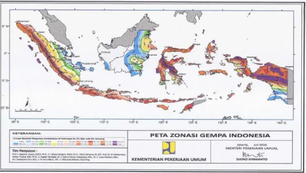
Gambar 2.18 Peta Respons Spektra Percepatan 0,2 detik di Batuan Dasar S
Buntuk Probabilitas Terlampaui 2% dalam 50 Tahun (redaman
5%) Berdasarkan RSNI 03-1726-201x ... 53
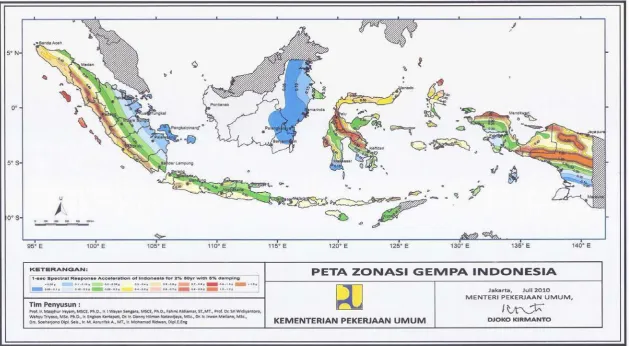
Gambar 2.19 Peta Respons Spektra Percepatan 1 detik di Batuan Dasar S
Buntuk Probabilitas Terlampaui 2% dalam 50 Tahun (redaman
5%) Berdasarkan RSNI 03-1726-201x ... 54
Gambar 2.20
Spectra Acceleration Bedrock
... 58
xiv
Gambar 2.22 Ilustrasi Perambatan Percepatan Gempa ... 59
Gambar 2.23 Spektrum Respons Desain ... 61
Gambar 2.24 Parabola Terbalik dan Beban Imbang [Aalami, 2005] ... 66
Gambar 2.25 Bagan Alir Solusi Interaksi dengan ADAPT-PT [Aalami, 2005] .. 67
Gambar 3.1 Gambar Tampak 3D Desain Awal ... 68
Gambar 3.2 Gambar Denah Kolom Gedung Pertemuan ... 69
Gambar 3.3 Gambar Denah Struktur Gedung Pertemuan Lantai 1, 2 dan 3 ... 69
Gambar 3.4 Denah Gedung Pertemuan Tampak Samping ... 70
Gambar 3.5 Langkah Kerja ... 74
Gambar 3.6 Denah Tipikal Bangunan ... 74
Gambar 3.7
Building Plan Grid System and Story Data Definition
... 75
Gambar 3.8
Edit Story Data
... 76
Gambar 3.9
Material Property Data
... 77
Gambar 3.10
Define Frame Properties
... 77
Gambar 3.11
Rectangular Section
untuk Balok
(sebelum
Reinforcement Data
diubah) ... 78
Gambar 3.12
Reinforcement Data
untuk Balok ... 78
Gambar 3.13
Rectangular Section
untuk Balok
(setelah
Reinforcement Data
diubah) ... 79
Gambar 3.14
Define Frame Properties
... 79
Gambar 3.15
Rectangular Section
untuk Kolom
(sebelum
Reinforcement Data
diubah) ... 80
Gambar 3.16
Reinforcement Data
untuk Kolom ... 80
Gambar 3.17
Rectangular Section
untuk Kolom
(setelah
Reinforcement Data
diubah) ... 81
Gambar 3.18
Define Frame Properties
... 81
Gambar 3.19
Wall / Slab Section
... 82
Gambar 3.20
Define Mass Source
... 82
Gambar 3.21
Assign Restraints
... 83
xv
Gambar 3.23
Assign Diaphragm
... 83
Gambar 3.24 Diafragma Lantai ... 84
Gambar 3.25
Set Analysis Option
... 85
Gambar 3.26
Dynamic Analysis Parameters
... 85
Gambar 3.27
P-Delta Parameters
... 86
Gambar 3.28
Response Spectrum Function
... 88
Gambar 3.29
Response Spectrum Cases
... 89
Gambar 3.30
Run Analysis
... 89
Gambar 3.31
Center Mass Rigidity
... 91
Gambar 3.32
Override Eccentricities
... 93
Gambar 3.33
Define Load Combinations
Sebelum COMB3 Dimasukkan ... 93
Gambar 3.34
Load Combination Data
untuk COMB3 ... 94
Gambar 3.35
Define Load Combinations
Setelah Semua
Kombinasi Pembebanan Dimasukkan ... 94
Gambar 3.36
Response Spectrum Case Data
... 95
Gambar 3.37 Hasil
Response Spectrum Base Reaction
... 95
Gambar 3.38
Response Spectra
... 96
Gambar 3.39 Respons Spektrum Gempa Rencana RSNI 03-1726-201x ... 100
Gambar 3.40
Response Spectrum NEHRP 97 Function Definition
... 101
Gambar 3.41
Response Spectrum Cases
... 102
Gambar 3.42
Run Analysis
... 102
Gambar 3.43
Center Mass Rigidity
... 105
Gambar 3.44
Override Eccentricities
... 106
Gambar 3.45
Define Load Combinations
Sebelum COMB3 Dimasukkan ... 107
Gambar 3.46
Load Combination Data
untuk COMB3 ... 107
Gambar 3.47
Define Load Combinations
Setelah Semua
Kombinasi Pembebanan Dimasukkan ... 108
xvi
Gambar 3.49 Hasil
Response Spectrum Base Reaction
... 109
Gambar 3.50
Response Spectra
... 109
Gambar 3.51 Balok Induk Beton Prategang yang Ditinjau ... 112
Gambar 3.52 Balok Anak Beton Prategang yang Ditinjau ... 138
Gambar 3.53
General Settings
... 165
Gambar 3.54
Design Settings
... 165
Gambar 3.55
Span Geometry
... 166
Gambar 3.56
Supports-Geometry
... 167
Gambar 3.57
Supports-Boundary Conditions
... 167
Gambar 3.58
Loading
... 168
Gambar 3.59
Material-Concrete
... 169
Gambar 3.60
Material-Reinforcement
... 169
Gambar 3.61
Material-Post-Tensioning
... 170
Gambar 3.62
Criteria-Allowable Stresses
... 171
Gambar 3.63
Criteria-Recommended Post-Tensioning Values
... 171
Gambar 3.64
Criteria-Calculation Options
... 172
Gambar 3.65
Criteria-Calculation Options
(
Long-term Loss Parametersi
) ... 173
Gambar 3.66
Criteria-Tendon Profile
... 174
Gambar 3.67
Criteria-Minimum Covers
... 175
Gambar 3.68
Criteria-Minimum Bar Extension
... 175
Gambar 3.69
Load Combination
... 176
Gambar 3.70
Criteria-Design Code
... 177
Gambar 3.71
PT Recycling
... 177
Gambar 3.72
PT Recycling Tendon Selection & Events
... 177
Gambar 3.73
Execution Succesfully Completed
... 178
Gambar 3.74 Perbandingan Respons Spektrun Gempa Rencana SNI
03-1726-2002 dan RSNI 03-1726-201x ... 183
Gambar 3.75
PT Recycling
untuk Balok Induk Beton Prategang ... 184
xvii
DAFTAR TABEL
Tabel 2.1
Perbedaan Beton Bertulang vs Beton Prategang ... 14
Tabel 2.2
Percepatan Puncak Batuan Dasar dan Percepatan Puncak Muka
Tanah untuk Masing-Masing Wilayah Gempa Indonesia [SNI
03-1726-2002] ... 51
Tabel 2.3
Klasifikasi Situs Berdasarkan RSNI 03-1726-201x ... 55
Tabel 2.4
Koefisien Situs,
F
aBerdasarkan RSNI 03-1726-201x ... 56
Tabel 2.5
Koefisien Situs,
Fv
Berdasarkan RSNI 03-1726-201x ... 57
Tabel 2.6
Koefisien
ξ
yang Membatasi Waktu Getar Alami Fundamental
Struktur Gedung [SNI 03-1726-2002] ... 60
Tabel 2.7
Load Combination
Yang Digunakan ... 63
Tabel 3.1
Dimensi Balok dan Kolom Bangunan ... 77
Tabel 3.2
Tabel
Modal Participating Mass Ratios
... 86
Tabel 3.3
Center Mass Rigidity
... 87
Tabel 3.4
Berat Struktur ... 87
Tabel 3.5
Response Spectrum Base Reaction
... 90
Tabel 3.6
Nilai Eksentrisitas Arah x untuk Pusat Gempa ... 92
Tabel 3.7
Nilai Eksentrisitas Arah y untuk Pusat Gempa ... 92
Tabel 3.8
Nilai Eksentrisitas Rencana untuk Pusat Gempa ... 92
Tabel 3.9
Point Displacement
... 96
Tabel 3.10
Kinerja Batas Layan Arah x ... 97
Tabel 3.11
Kinerja Batas Layan Arah y ... 97
Tabel 3.12
Analisa
Δ
m Akibat Gempa Arah x ... 97
Tabel 3.13
Analisa
Δ
m Akibat Gempa Arah y ... 98
Tabel 3.14
Response Spectrum Base Reaction
... 103
Tabel 3.15
Nilai Eksentrisitas Arah x untuk Pusat Gempa ... 105
Tabel 3.16
Nilai Eksentrisitas Arah y untuk Pusat Gempa ... 105
Tabel 3.17
Nilai Eksentrisitas Rencana untuk Pusat Gempa ... 106
xviii
Tabel 3.19
Kinerja Batas Layan Arah x ... 110
Tabel 3.20
Kinerja Batas Layan Arah y ... 110
Tabel 3.21
Analisa
Δ
m Akibat Gempa Arah x ... 111
Tabel 3.22
Analisa
Δ
m Akibat Gempa Arah y ... 111
Tabel 3.23
Waktu Getar Alami ... 179
Tabel 3.24
Gaya Geser Dasar ... 179
Tabel 3.25
Peralihan (
Displacement
) Arah x ... 180
Tabel 3.26
Peralihan (
Displacement
) Arah y ... 180
Tabel 3.27
Drift Δs
Antar Tingkat Arah x ... 181
Tabel 3.28
Drift Δs
Antar Tingkat Arah y ... 181
Tabel 3.29
Drift Δm
Antar Tingkat Arah x ... 182
Tabel 3.30
Drift Δm
Antar Tingkat Arah y ... 182
Tabel 3.31
Gaya Dalam Balok Induk Beton Prategang ... 184
xix
DAFTAR NOTASI DAN SINGKATAN
a
: Tinggi balok tegangan persegi ekivalen
ABS :
Scaled
Absolute Sum Method
ACI
:
American Concrete Institute
Ac
: Luas beton pada penampang yang ditinjau
Aps
: Luas tulangan prategang dalam daerah tarik, mm
2A
s: Luas tulangan yang diperlukan
As min
: Luas tulangan minimum, mm
2A
s max: Luas tulangan maksimum, mm
2
A
sl: Luas total tulangan longitudinal, mm
2
A
v: Luas tulangan, mm
2b
w: Lebar penampang, mm
C
a: Faktor Respons Gempa dinyatakan dalam percepatan gravitasi yang nilainya
bergantung pada waktu getar alami struktur gedung dan kurvanya
ditampilkan dalam Spektrum Respons Gempa Rencana.
C
b: Garis berat bawah
Cc’
: Gaya tekan pada beton
Cs’
: Gaya pada tulangan tekan
Ct
: Garis berat atas
Cv
: Faktor Respons Gempa vertikal untuk mendapatkan beban gempa vertikal
nominal statik ekuivalen pada unsure struktur gedung yang memiliki
kepekaan yang tinggi terhadap gravitasi.
d
: Tinggi efektif penampang, mm
di
: Lengan momen prategang tulangan non komposit
DL
: Beban mati, berat dari semua bagian suatu gedung yang bersifat tetap
dp
: Lengan momen prategang komposit
dpi
: Lengan momen prategang non komposit
Ec
: Modulus elastisitas beton, MPa
xx
Eqx
: Beban gempa arah x
Eqy
: Beban gempa arah y
f’c
: Kuat tekan beton yang disyaratkan, MPa
f’ci
: Kuat tekan beton pada saat pemberian prategang awal, MPa
fpc
: Tegangan tekan beton rata-rata akibat gaya prategang efektif saja (sesudah
memperhitungkan semua kehilangan prategang yang mungkin terjadi), MPa
fps
: Tegangan pada tulangan prategang disaat penampang mencapai kuat
nominalnya, MPa
fpu
: Kuat tarik tendon prategang yang disyaratkan, MPa
fpy
: Kuat leleh tendon prategang yang disyaratkan, MPa
fy
: Kuat leleh tulangan yang disyaratkan, MPa
f’ys
: Kuat leleh tulangan tranversal yang disyaratkan, MPa
g
: Percepatan gravitasi
h
: Tebal total komponen struktur, mm
h
i: Ketinggian lantai tingkat ke-i, diukur dari taraf penjepitan lateral
hmin
: Tinggi minimum balok, mm
I
: Faktor keutamaan gedung
LL
: Beban hidup, semua beban yang terjadi akibat penghunian atau penggunaan
suatu gedung
L
n: Bentang bersih untuk momen positif atau geser dan rata-rata dari
bentang-bentang bersih yang bersebelahan untuk momen negative
M
u: Momen terfaktor pada penampang, Nmm
M
n: Momen nominal penampang
n
p: Jumlah pelat
Pu
: Beban aksial terfaktor, N
Psu
: Gaya tendon prategang pada ujung angkur, N
R
: Faktor reduksi gempa
s
: Jarak antar sengkang, mm
SDL
: Beban mati tambahan
xxi
S
D1: Parameter percepatan spektrum percepatan desain periode 1 detik
SNI
: Standar Nasional Indonesia
SRSS
:
Square Root of the Sum of the Squares
S
s: Parameter respons spektral percepatan gempa MCE
Rterpetakan pada
periode pendek, T = 0,2 detik
t
: Umur beton saat ditegangkan, hari
T
: Waktu getar alami struktur
Tp
: Gaya pada kabel prategang
Ts
: Gaya pada tulangan tarik
Vb
:
Base Shear
Struktur
Vc
: Kuat geser nominal yang dipikul oleh beton, N
Vs
: Gaya geser dasar nominal akibat beban gempa yang dipikul oleh suatu jenis
subsistem struktur gedung tertentu di tingkat dasar
Vs max
: Gaya geser maksimum
V
u: Gaya geser terfaktor pada penampang, N
W
: Berat total gedung, termasuk beban hidup yang sesuai
x
: Jarak garis netral dari serat tekan terluar
Δε
p: Regangan kabel prategang akibat lentur
α
: Rasio kekakuan lentur prategang balok terhadap balok bertahap kekakuan
lentur penampang balok terhadap kekakuan lentur pelat dengan lebar yang
dibatasi secara lateral oleh garis-garis sumbu tengah dari panel yang
bersebelahan (bila ada) pada tiap sisi balok
Δ
: Simpangan antar lantai tingkat desain
Δ
m: Rasio antara simpangan maksimum struktur gedung akibat pengaruh gempa
rancana pada saat mencapai kondisi di ambang keruntuhan
Β
: Faktor pelapis
γ
beton: Berat jenis beton
Ø
: Diameter baja tulangan
ξ
: Koefisien yang membatasi waktu getar alami fundamental struktur gedung
xxii
ϕ
: Faktor kekuatan
ϕ
s: Faktor kekuatan geser
ρ
: Rasio tulangan tekan non-prategang
ρ
b: Rasio tulangan yang memberikan kondisi regangan seimbang
ε
pi: Regangan awal kabel prategang
xxiii
DAFTAR LAMPIRAN
Lampiran 1 Peta Wilayah Gempa ... 189
Lampiran 2 Spesifikasi VSL ... 193
Lampiran 3 Hasil
Output
Program ADAPT-PT untuk Balok Induk Beton
Prategang ... 215
Lampiran 3 Hasil
Output
Program ADAPT-PT untuk Balok Anak Beton
189
LAMPIRAN 1
190
Gambar L1.1Wilayah Gempa Indonesia dengan Percepatan Puncak Batuan Dasar dengan Perioda Ulang 500 Tahun
191
Gambar L1.2 Peta Respons Spektra Percepatan 0,2 detik di Batuan Dasar S
Buntuk Probabilitas Terlampaui 2% dalam 50
192
Gambar L1.3 Peta Respons Spectra Percepatan 1 detik di Batuan Dasar S
Buntuk Probabilitas Terlampaui 2% dalam 50
193
LAMPIRAN 2
V S L M U LT I S T R A N D S Y S T E M S :
Strand and Tendon Properties
Strands Type 0.5” (270 ksi)
Number of Strands Per
Tendon
Area of tendon inch2
Min breaking load kips
1 0.15 41.3 2 0.31 82.6 3 0.46 123.9 4 0.61 165.2 5 0.77 206.5 6 0.92 247.8 7 1.07 289.1 8 1.22 330.4 9 1.38 371.7 10 1.53 413.0 11 1.68 454.3 12 1.84 495.6 13 1.99 536.9 14 2.14 578.2 15 2.30 619.5 16 2.45 660.8 17 2.60 702.1 18 2.75 743.4 19 2.91 784.7 20 3.06 826.0 21 3.21 867.3 22 3.37 908.6 23 3.52 949.9 24 3.67 991.2 25 3.83 1032.5 26 3.98 1073.8 27 4.13 1115.1 28 4.28 1156.4 29 4.44 1197.7 30 4.59 1239.0 31 4.74 1280.3 32 4.90 1321.6 33 5.05 1362.9 34 5.20 1404.2 35 5.36 1445.5 36 5.51 1486.8 37 5.66 1528.1 38 5.81 1569.4 39 5.97 1610.7 40 6.12 1652.0 41 6.27 1693.3 42 6.43 1734.6 43 6.58 1775.9 44 6.73 1817.2 45 6.89 1858.5 46 7.04 1899.8 47 7.19 1941.1 48 7.35 1982.4 49 7.50 2023.7 50 7.65 2065.0 51 7.80 2106.3 52 7.96 2147.6 53 8.11 2188.9 54 8.26 2230.2 55 8.42 2271.5
Strands Type 0.6” (270 ksi)
Number of Strands Per
Tendon
Area of tendon inch2
Min breaking load kips
1 0.22 58.6 2 0.43 117.2 3 0.65 175.8 4 0.87 234.4 5 1.09 293.0 6 1.30 351.6 7 1.52 410.2 8 1.74 468.8 9 1.95 527.4 10 2.17 586.0 11 2.39 644.6 12 2.60 703.2 13 2.82 761.8 14 3.03 820.4 15 3.26 879.0 16 3.47 937.6 17 3.69 996.2 18 3.91 1054.8 19 4.12 1113.4 20 4.34 1172.0 21 4.56 1230.6 22 4.78 1289.2 23 4.99 1347.8 24 5.21 1406.4 25 5.43 1465.0 26 5.64 1523.6 27 5.86 1582.2 28 6.08 1640.8 29 6.29 1699.4 30 6.51 1758.0 31 6.73 1816.6 32 6.94 1875.2 33 7.16 1933.8 34 7.38 1992.4 35 7.60 2051.0 36 7.81 2109.6 37 8.03 2168.2 38 8.25 2226.8 39 8.46 2285.4 40 8.68 2344.0 41 8.90 2402.6 42 9.11 2461.2 43 9.33 2519.8 44 9.55 2578.4 45 9.77 2637.0 46 9.98 2695.6 47 10.20 2754.2 48 10.42 2812.8 49 10.63 2871.4 50 10.85 2930.0 51 11.07 2988.6 52 11.28 3047.2 53 11.50 3105.8 54 11.72 3164.4 55 11.94 3223.0
Strand Type 0.5” (13 mm)
0.6” (15 mm)
Nominal diameter inch 0.5 0.6
Nominal area inch2 0.153 0.217 Nominal weight/mass lbs/ft 0.53 0.74
Tensile strength ksi 270 270 Min. breaking load kips 41.3 58.6
Young’s modulus ksi approx. 28,500
Relaxation % max 2.5
Strand Properties
Tendon Properties
www.vsl.net
888-489-2687
www.vsl.net • 888-489-2687
Notes:
Anchorage spacings are in accordance with test requirement of AASHTO (The Special Anchorage Device Acceptance Test Procedure, AASHTO 2000).
For proper design and detailing of anchorage zones and related reinforcement, refer to the VSL Publication Detailing for Post-Tensioning.
Dimensions are valid for:
• f’ci (psi) is the nominal minimum concrete cylinder strength at the time of stressing. • Maximum prestressing force may be applied when concrete reaches a cylinder
strength of 3,500 psi (24 MPa) and 5,500 psi (38 MPa) respectively. • Temporary overstressing to 80% of Guaranteed Ultimate Tensile Strength. • Yield strength of spiral reinforcement: Grade 60 (400 MPa).
• Tie one and one-half turns of spiral at both ends.
• Additional orthogonal reinforcement may be required in the local anchorage zone as determined by design.
• Spirals may be replaced by suitable orthogonal reinforcement.
• Information for other concrete strengths and conditions is available from your local VSL Representative.
• Spiral reinforcement shall be centered on the anchorage assembly and be placed directly behind the bearing plate as indicated above.
V S L M U LT I S T R A N D S Y S T E M S :
Type ECI Stressing Anchorage
Dimensions (Inches)
Tendon Unit
f’ci
(psi) A B C øD øE
øF PT+ Duct øF Steel Duct øF SCH 40 Pipe øG H K PT+ Duct K Steel Duct K SCH 40 Pipe
L n P Q R X
6-7 3500 8.54 6.69 2.37 5.33 3.31 2.87 2.88 3.00 11.00 12.00
No Trumpet on 6-7 #4 6.50 3.00 7.40 4.17 13.00 6-7 5500 8.54 6.69 2.37 5.33 3.31 2.87 2.88 3.00 11.00 12.00 #4 6.50 3.00 7.40 4.17 13.00 6-12 3500 9.88 8.66 3.00 6.85 4.62 3.58 3.24 3.50 13.00 14.00
No Trumpet on 6-12 #5 7.00 3.00 8.66 4.90 15.00 6-12 5500 9.88 8.66 3.00 6.85 4.62 3.58 3.24 3.50 13.00 13.50 #4 7.00 3.00 8.66 4.90 15.00 6-19 3500 11.42 6.91 3.75 8.13 5.90 4.57 4.10 4.50 17.00 19.00 15.19 12.09 9.29 #5 11.50 2.00 10.24 5.63 19.00 6-19 5500 11.42 6.91 3.75 8.13 5.90 4.57 4.10 4.50 15.00 17.00 15.19 12.09 9.29 #5 10.50 2.00 10.24 5.63 17.00
VSL
Multistrand Post-Tensioning
VSL/ DSUS_Multi_SA_ES 1M 5/ 02 © VStructural, LLC w w w.vsl.net 2
Stressing Anchorage VSL Type ES
Dimensions Inches Tendon Unit
Anchorage spacings are in accordance w ith test requirements of FIP (Recommendations for Acceptance of Post-Tensioning Systems: March 1992). For proper design and detailing of anchorage zones and related reinforcement, refer to the VSL Publication “Detailing for Post-Tensioning”.
Dimensions are valid for:
• Nominal concrete cylinder strength at 28 days: 4,000 psi (28 MPa).
• Maximum prestressing force may be applied w hen concrete reaches a cylinder strength of 3,500 psi (24 MPa).
• Temporary overstressing to 80% of Guaranteed Ultimate Tensile Strength.
• Yield strength of spiral reinforcement: Grade 60 (400 MPa).
• Additional orthogonal reinforcement may be required in the local anchorage zone as determined by design.
• Spirals may be replaced by suitable orthogonal reinforcement.
• Information for other concrete strengths and conditions are available from your local VSL Representative.
Spiral reinforcement shall be centered on the anchorage assembly and be placed directly behind the bearing plate.
Other sizes available on request Subject to modification
Draw ing s not to scale
~1.25" K (std)
K (super) øG øA H C B Spiral reinforcement L x n turns (pitch = H/n)
X = Anchorage spacing XR = Clearence to edge
XR = X + required cover of
spiral reinforcing øD øE J 1 2 S tr a n d T y p e 0 .5 '' S tr a n d Ty p e 0 .6 ''
øA B C øD øE øG H J K K L n X
(std) (super)
5-12 8.74 2.36 2.38 6.00 4.06 10.50 10.00 4.33 13.00 16.38 #4 5 12.50
5-19 10.16 3.15 3.00 7.00 5.13 13.75 14.00 4.82 16.93 20.22 #5 7 15.75
5-31 12.60 3.94 4.00 9.00 6.59 18.00 18.00 5.91 19.69 23.86 #5 9 20.50
5-43 15.35 4.72 5.20 11.10 8.57 21.75 20.00 7.24 28.75 NA #5 10 23.75
5-55 16.54 5.12 5.50 12.00 9.01 24.75 22.50 7.80 27.55 NA #6 10 26.75
6-7 8.74 2.36 2.38 6.00 4.06 10.50 10.00 4.33 13.00 16.38 #4 5 12.50
6-12 10.16 3.15 3.25 7.00 5.13 13.75 14.00 4.82 16.93 20.22 #5 7 15.75
6-19 11.81 3.54 3.75 8.25 5.88 17.00 18.00 5.61 19.69 22.13 #5 9 19.00
6-22 12.60 3.94 4.00 9.00 6.59 18.00 18.00 5.91 19.69 23.86 #5 9 20.50
6-31 15.35 4.72 5.20 11.10 8.57 21.75 20.00 7.24 28.75 NA #5 10 23.75
VSL
Multistrand Post-Tensioning
VSL/ DSUS_Multi_SA_EC 1M 5/ 02 © VStructural, LLC w w w.vsl.net 3
Stressing Anchorage VSL Type EC
Anchorage spacings are in accordance w ith test requirements of FIP (Recommendations for Acceptance of Post-Tensioning Systems: March 1992). For proper design and detailing of anchorage zones and related reinforcement, refer to the VSL Publication “Detailing for Post-Tensioning”.
Dimensions are valid for:
• Nominal concrete cylinder strength at 28 days: 4,000 psi (28 MPa).
• Maximum prestressing force may be applied w hen concrete reaches a cylinder strength of 3,500 psi (24 MPa).
• Temporary overstressing to 80% of Guaranteed Ultimate Tensile Strength.
• Yield strength of spiral reinforcement: Grade 60 (400 MPa).
• Spirals may be replaced by suitable orthogonal reinforcement.
• Information for other concrete strengths and conditions are available from your local VSL Representative.
Spiral reinforcement shall be centered on the anchorage assembly and be placed directly behind the bearing plate.
Additional orthogonal reinforcement may be required in the local anchorage zone as determined by design.
Other sizes available on request Subject to modification
Dimensions Inches Tendon Unit S tr a n d T y p e 0 .5 ''
~1.25" H øG
A B
C
Spiral reinforcement L x n turns (pitch = H/n)
øD øE øF
X = Anchorage spacing XR = Clearence to edge XR = X + required cover of
spiral reinforcing
1 2
A
A B C øD øE øF øG H L n X
5-7 6.50 5.25 2.38 4.50 2.91 2.50 9.00 12.00 #4 6 9.50
5-12 8.88 7.06 2.38 6.00 4.31 3.13 11.75 16.00 #4 8 12.50
5-19 11.00 10.25 3.00 7.00 5.56 3.75 15.00 18.00 #5 8 15.75
5-27 12.38 13.63 4.00 9.00 7.00 4.75 18.00 18.00 #6 8 18.75
Dimensions (Inches)
Tendon Unit A B C øD øE F øG H J J 2) L n X
0.5” Strand
5-1 2.76 0.59 1.77 1.65 0.59 2.76 3.15 3.54 0.98 1.18 #3 2 3.54 5-3 4.53 0.79 1.97 3.54 1.97 7.48 5.12 5.91 1.57 1.17 #4 3 6.10 5-4 5.12 0.79 1.97 3.74 2.17 7.48 6.30 5.91 1.77 1.97 #4 3 7.09 5-7 6.89 0.98 2.17 4.33 2.91 7.48 8.07 7.87 2.17 2.36 #4 4 9.25 5-12 9.06 1.38 2.36 5.91 4.09 14.57 11.22 9.84 2.56 2.83 #4 5 12.01 5-19 11.42 1.57 2.95 7.09 5.31 18.50 14.37 11.81 3.15 3.43 #5 6 15.16 5-22 12.40 1.77 3.35 7.48 5.91 18.90 15.55 14.17 3.35 3.62 #6 6 16.34 5-31 14.57 2.17 3.74 9.06 6.77 21.65 18.50 15.75 3.94 4.21 #5 8 19.29 5-37 15.94 2.36 4.13 9.45 7.40 22.44 20.08 16.54 4.72 5.00 #7 7 21.06 5-43 17.32 2.36 4.33 10.24 8.50 26.77 21.65 18.90 5.12 5.39 #7 8 22.83 5-55 19.69 2.76 5.12 11.42 9.06 26.77 24.41 21.26 5.51 5.91 #7 9 25.79
0.6” Strand
6-1 2.95 0.59 1.97 2.09 0.71 2.76 3.15 3.54 1.18 1.38 #3 2 4.13 6-2 4.33 0.59 1.97 3.54 1.97 7.48 5.12 5.91 1.77 1.97 #4 3 5.91 6-3 5.31 0.79 1.97 3.74 2.20 7.48 6.30 5.91 1.77 1.97 #4 3 7.28 6-4 6.30 0.98 2.17 4.33 2.56 7.48 7.48 7.87 1.97 2.17 #4 4 8.27 6-7 8.07 1.38 2.36 5.31 3.31 11.42 10.24 9.84 2.36 2.64 #4 5 11.02 6-12 10.63 1.57 2.95 6.69 4.65 18.11 13.58 11.81 3.15 3.43 #5 6 14.37 6-19 13.39 1.97 3.74 7.87 5.91 23.23 17.32 13.78 3.74 4.02 #5 9 18.11 6-22 14.57 2.17 3.94 8.66 6.77 27.17 18.50 15.75 4.33 4.61 #6 8 19.49 6-31 17.13 2.56 4.72 10.24 7.56 27.17 22.05 18.90 5.12 5.39 #7 8 23.23 6-37 18.90 2.76 5.31 11.02 8.46 32.68 24.02 21.26 5.51 5.91 #7 9 25.20 6-43 20.47 2.95 5.71 11.81 9.69 37.40 25.59 25.20 5.91 6.30 #8 8 27.17 6-55 22.83 3.54 6.30 13.39 10.04 37.40 29.13 24.80 6.69 7.09 #8 9 30.71
www.vsl.net • 888-489-2687
Grout Hose Bearing Plate (Steel) Duct Trumpet Anchor Head~1.25" H øG
A F C B ø D ø E
X = Anchorage spacing XR = Clearance to edge XR = X + required cover of spiral reinforcing
1 2
A
Spiral reinforcement L x n turns (pitch = H/n)
V S L M U LT I S T R A N D S Y S T E M S :
Type E Stressing Anchorage
Notes:
• Other sizes available on request.
• Anchorage spacings are in accordance with test requirements of FIP (Recommendations for Acceptance of Post-Tensioning Systems: March 1992). For proper design and detailing of anchorage zones and related reinforcement, refer to the VSL Publication Detailing for Post-Tensioning.
Dimensions are valid for:
• Nominal minimum concrete cylinder strength at 28 days: 4000 psi (28 MPa).
• Maximum prestressing force may be applied when concrete reaches a cylinder strength of 3,500 psi (24 MPa). • Temporary overstressing to 80% of Guaranteed Ultimate Tensile Strength.
• Yield strength of spiral reinforcement: Grade 60 (400 MPa).
• Information for other concrete strength and conditions are available from your local VSL Representative.
• Large bearing plates are available where bearing stress is arbitrarily limited to 3,000 psi (21 MPa) with the tendon locked off at 70% Guaranteed Ultimate Tensile Strength.
• Spiral reinforcement shall be centered on the anchorage assembly and be placed directly behind the bearing plate. • Additional orthogonal reinforcement may be required in the local anchorage zone as determined by design.
V S L M U LT I S T R A N D S Y S T E M S :
Type K Coupler
www.vsl.net • 888-489-2687
Bearing Plate Type EC, ES or E Grout HoseDuct Coupling
Head K
Trumpet
Tension Ring Compression
Fittings
Dimensions (Inches)
Tendon Unit A B C øD
0.5” Strand
5-3 16.93 5.51 1.57 5.12 5-7 21.65 5.51 2.36 6.69 5-12 25.59 5.51 2.36 7.87 5-19 29.13 5.51 3.15 9.45 5-22 32.68 5.51 3.54 10.24 5-31 44.88 5.51 3.54 13.78 5-37 51.97 7.09 4.72 15.35 5-42 50.79 7.09 5.12 15.55 5-55 53.94 7.87 5.91 16.54
0.6” Strand
6-2 14.96 5.91 1.18 5.51 6-3 19.29 6.30 2.36 5.91 6-4 20.47 6.30 2.36 6.30 6-7 24.80 6.30 2.76 7.48 6-12 28.74 6.30 3.15 9.45 6-19 33.86 6.30 3.54 11.02 6-22 36.61 6.30 3.54 12.20 6-31 42.91 7.09 5.12 14.17 6-37 54.72 7.87 5.12 16.93
VSL US Technical Data and Dimensions • K Multistrand • 0308 ©VStructural, LLC
Notes:
• Tension ring required as shown.
V S L M U LT I S T R A N D S Y S T E M S :
Type T Dead-End Anchorage
Notes:
• Anchorage spacings are in accordance with test requirement of AASHTO (The Special Anchorage Device Acceptance Test Procedure, AASHTO 2000).
• For proper design and detailing of anchorage zones and related reinforcement, refer to the VSL Publication Detailing for Post-Tensioning.
Dimensions are valid for:
• Nominal minimum concrete cylinder strength at 28 days: 4000 psi (28 MPa).
• Maximum prestressing force may be applied when concrete reaches a cylinder strength of 3,500 psi (24 MPa).
• Temporary overstressing to 80% of Guaranteed Ultimate Tensile Strength.
• Information for other concrete strength and conditions are available from your local VSL Representative.
Dimensions (Inches)
Tendon Unit A B C øG X
0.5” Strand
5-12 6.60 8.80 36.00 11.75 12.50 5-19 11.00 11.00 36.00 15.00 15.75 5-31 16.00 11.00 36.00 19.00 20.00 0.6”
Strand
6-7 6.75 6.75 36.00 12.50 6-12 6.75 6.00 36.00 15.75 6-19 9.00 11.25 36.00 20.00
Spiral reinforcement L x n turns (pitch = H/n)
Tension Ring X = Anchorage spacing
XR = Clearance to edge
XR = X + required cover of
spiral reinforcing
C øG
B
A
www.vsl.net • 888-489-2687
Type T Anchorage Grout HoseSeal Duct Tension Ring
V S L M U LT I S T R A N D S Y S T E M S :
Type Z Intermediate Anchorage
Notes:
• Tension ring required on #2 side of the anchorage. • Blockout dimensions dependent upon the shape of the
concrete surface and the tendon elongation.
• The values stated apply for surfaces which are not curved.
Dimensions (Inches)
Tendon Unit A B C D F 2 G 2 H
0.5” Strand
5-2 1) 5.12 2.36 3.15 2.36 15.75 22.05 6.69
5-4 1) 6.30 2.76 3.54 2.56 19.69 28.35 7.87
5-6 7.87 3.54 5.12 3.35 23.62 35.04 9.45 5-8 8.62 4.12 4.50 3.00 29.50 46.38 10.25 5-12 11.02 5.51 5.51 3.54 39.37 56.69 12.60 5-22 13.78 6.69 7.87 4.72 57.09 81.50 15.35
0.6” Strand
6-2 1) 5.51 2.76 3.54 2.56 17.72 24.41 7.09
6-4 1) 6.69 3.15 3.94 2.76 35.43 44.49 8.27
6-6 8.27 3.94 5.51 3.54 39.37 51.97 9.84 6-12 11.81 6.30 6.30 3.94 53.15 75.20 13.39 6-22 15.75 7.48 9.84 5.71 59.06 90.16 17.32
Tendon #2
Tension Ring
Tendon #1
F + L B
G + L
Curved stressing chair Stressing Jack D C E Tendon #2 H Tendon #1 A
L = Elongation of tendon #2
E = C/2 + required cover
www.vsl.net • 888-489-2687
Retainer Plate Grout HoseAnchor Head Type Z
Tension Ring
with Anchors Duct
VSL
Multistrand Post-Tensioning
VSL/ DSUS_Multi_DEA_L 1M 5/ 02 © VStructural, LLC w w w.vsl.net 8
Dead-End Anchorage VSL Type L
For proper design and detailing of anchorage zones and related reinforcement, refer to the VSL Publication “Detailing for Post-Tensioning”.
Dimensions are valid for:
• Nominal concrete cylinder strength at 28 days: 4,000 psi (28 MPa).
• Maximum prestressing force may be applied w hen concrete reaches a cylinder strength of 3,500 psi (24 MPa).
• Temporary overstressing to 80% of Guaranteed Ultimate Tensile Strength.
• Yield strength of spiral reinforcement: Grade 60 (400 MPa).
• Custom size VSL Loops are available.
• Information for other concrete strengths and conditions are available from your local VSL Representative.
• Simultaneous stressing of both tendon ends is necessary.
Other sizes available on request Subject to modification
Dimensions Inches Tendon Unit
S
tr
a
n
d
T
y
p
e
0
.5
'' øA Internal øA External R min.
5-7 2.62 2.88 24.00
5-12 3.50 3.75 36.00
5-19 3.94 4.19 36.00
5-31 5.75 6.00 36.00
Hairpin bar reinforcement R
www.vsl.net • 888-489-2687
Notes:
• Anchorage spacings are in accordance with test requirement of AASHTO (The Special Anchorage Device Acceptance Test Procedure, AASHTO 2000).
• For proper design and detailing of anchorage zones and related reinforcement, refer to the VSL Publication Detailing for Post-Tensioning.
Dimensions are valid for:
• Nominal minimum concrete cylinder strength at 28 days: 4000 psi (28 MPa).
• Maximum prestressing force may be applied when concrete reaches a cylinder strength of 3,500 psi (24 MPa).
• Temporary overstressing to 80% of Guaranteed Ultimate Tensile Strength. • Yield strength of spiral reinforcement: Grade 60 (400 MPa).
• Spirals may be replaced by suitable orthogonal reinforcement.
• Information for other concrete strength and conditions are available from your local VSL Representative.
V S L M U LT I S T R A N D S Y S T E M S :
Type AF Dead-End Anchorage
Dimensions (Inches)
Tendon Unit øA C D E øF
Int.
øF (2)
Ext. øG H K øL n M X
0.6” Strand
6-12 10.43 2.36 18.11 3.54 3.74 4.02 14.96 17.72 27.56 #5 9.00 2.36 16.00 6-19 12.40 2.36 18.11 3.54 4.72 5.00 18.90 21.26 27.56 #6 9.00 2.36 20.00 6-31 14.76 2.36 25.98 3.54 5.91 6.18 24.41 25.98 35.43 #7 12.00 3.15 26.00
VSL US Technical Data and Dimensions • AF Multistrand • 0308 ©VStructural, LLC
Duct Trumpet Strand Cover Plate E D ØG L C K H M ØF
XR= Clearance to edge 1st. injection
2nd injection
Overflow of 1st. injection
ØA
X = Anchorage spacing
Eccentricity of the Center of Gravity of Strands
TypeUnit Dimensions (Inches)
0.6” ØA ØB ØC D E F G H
59mm 6-7 2.28 2.48 2.87 0.10 1.65 3.23 4.25 4.17 76mm 6-12 2.99 3.19 3.58 0.10 2.00 3.94 4.57 4.88 100mm 6-19 / 22 3.94 4.17 4.57 0.12 2.00 4.84 4.96 5.79 115mm 6-27 4.53 4.76 5.16 0.12 2.36 5.43 5.00 5.83 130mm 6-31 / 37 5.12 5.35 5.75 0.12 2.00 6.14 5.47 6.97 150mm 6-43 / 55 5.91 6.18 6.57 0.14 2.36 6.89 4.96 7.28
V S L M U LT I S T R A N D S Y S T E M S :
PT-Plus™ Duct
Ducts PT-Plus™ System
Polypropylene (PP) Plastic Duct
G H Grout /vent
connection E
ø
A
D
ø
B
ø
C
ø
F
1
.5
0
.8
8
www.vsl.net • 888-489-2687
VSL US Technical Data and Dimensions • Multistrand Duct • 0708 ©VStructural, LLC Duct System Eccentricity Offset 1 Offset 2
A
A
Strand projection B
Concrete cover according to applicable standard
B
C
D
E
E
VSL
Multistrand Post-Tensioning
VSL/ DSUS_Multi_Block/ Clear+ 1M 5/ 02 © VStructural, LLC w w w.vsl.net 11
Block Out Dimensions and Clearance Requirement
Dimensions in inches.
Jack Type A min. B C D E
ZPE-23FJ - 12.00 47.25 4.57 3.50
ZPE-30 1.18 24.00 43.50 5.51 4.00
ZPE-3 1.18 22.00 39.50 7.87 6.00
ZPE-60 1.18 26.00 43.50 7.09 5.50
ZPE-7A 1.18 32.00 47.25 11.81 8.00
ZPE-12St2 1.97 28.00 51.25 12.20 8.00
ZPE-200 1.97 44.00 82.75 12.99 8.25
ZPE-19 1.97 34.00 59.25 15.35 10.00
ZPE-460/ 31 2.36 28.00 59.25 19.09 12.00
ZPE-500 3.15 46.00 78.75 23.03 13.00
ZPE-750 3.15 54.00 90.75 22.44 14.50
ZPE-1000 3.15 52.00 86.75 31.10 17.75
VSL
Multistrand Post-Tensioning
VSL/ DSUS_Multi_Jacks 1M 5/ 02 © VStructural, LLC w w w.vsl.net 12
Stressing Jack Data
Type I (ZPE-23FJ)
Type II (ZPE-19)
Type III (ZPE-500)
Designation ZPE-23FJ ZPE-30 ZPE-3 ZPE-60 ZPE-7A ZPE-12St2 ZPE-200 ZPE-19 ZPE-460/31 ZPE-500 ZPE-750 ZPE-1000
Type I III III III III II III II II III II III
Length (in) 31.10 28.35 18.70 24.21 27.17 21.65 37.80 29.53 22.83 39.37 46.65 47.24
Diameter (in) 4.57 5.51 7.87 7.09 11.02 12.20 12.40 15.35 19.09 21.65 20.47 31.10
Stroke (in) 7.87 9.84 6.30 9.84 6.30 3.94 11.81 3.94 3.94 7.87 5.91 7.87
Piston area (in^2) 7.30 9.04 16.06 19.59 31.56 47.96 50.48 77.55 124.62 138.66 193.29 280.47
Capacity (kips) 52 72 112 142 239 416 450 652 1048 1124 1686 2248
Pressure (psi) 7078 7963 7005 7252 7585 8673 8905 8412 8412 8108 8717 8021
Weight (lb) 51 62 104 163 254 333 672 648 959 2346 2425 5049
Used for 13 mm 5-1 5-1 5-2, 5-3 5-2 5-6, 5-7 5-12 5-12 5-18 5-22 5-22 5-31 5-37
(0.5'') tendon types to 5-4 5-19 5-31 5-31 5-37 to 5-55
Used for 15 mm 6-1 6-1 6-2 6-2, 6-3 6-4 6-6, 6-7 6-6, 6-7 6-12 6-18, 6-18 6-31 6-31
(0.6'') tendon types 6-19 to 6-22 to 6-43
Grout tube
Wedg es
Strands
Recess former
Flat duct
Anchorag e body Trumpet
VSL
Bonded Slab Post-Tensioning
VSL/ DSUS_Bonded_SA_SO 1M 5/ 02 © VStructural, LLC w w w.vsl.net 13
Stressing Anchorage VSL Type SO
Type 6-41 A 13.00 B 6.62 C 11.25 D 4.90 E 3.00 F 5.00 H2 K-1.2 J 3.00 Kmin 4.75 Lmin3
1.5 x K M #4 N #5 X 13.88
For proper design and detailing of anchorage zones and related reinforcement, refer to the VSL Publication “Detailing for Post-Tensioning”.
Dimensions in inches.
Dimensions are valid for:
• Nominal concrete cylinder strength at 28 days: 4,000 psi (28 MPa).
• Maximum prestressing force may be applied w hen concrete reaches a cylinder strength of 80% of its nominal strength or 3,500 psi (24 MPa) w hichever is less.
• Temporary overstressing to 80% of Guaranteed Ultimate Tensile Strength.
• Information for other concrete strengths and conditions are available from your local VSL Representative.
1) Anchorage may be used w ith 0.5” (12.7 mm) or 6” (15.2 mm) strand.
2) Use actual K w hen calculating H.
3) L shall be the maximum permitted by the slab thickness and cover, w hereas Lmm= 1.5 x K.
Other sizes available on request Subject to modification
øN F H J
90 250 E Grout tube General slab reinforcement
Detail of reinforcement
For proper design and detailing of anchorage zones and related reinforcement, refer to the VSL Publication "Detailing for Post-Tensioning". The arrangement shown here is common for slabs in buildings.
X = Anchorage spacing XR = Clearence to edge
XR = X + required cover of
VSL
Bonded Slab Post-Tensioning
VSL/ DSUS_Bonded_Duct/ CoupSK 1M 5/ 02 © VStructural, LLC w w w.vsl.net 14 Dimensions in inches.
Dimensions of Ducts
Type
SK 5-4
G
16.06
H
5.91
J
5.51
K
6.69
Coupler VSL Type SK
Dimensions in inches.
Dimensions are valid for nominal concrete streng th: 20 MPa (cube), 16 MPa (cylinder), at the time of stressing , for a maximum stressing force of 80% of the tendon breaking load.
Tendon unit h H b B s
5-2, 6-2 0.75 1.18 1.65 2.09 0.08 5-4, 6-4 0.83 1.38 2.83 3.39 0.08 5-4, 6-4 0.71 0.83 2.83 2.95 0.01
Plastic
duct PT-PLUSTM
Plastic
duct PT-PLUSTM
Steel duct
B b
s
H
VSL
Bonded Slab Post-Tensioning
VSL/ DSUS_Bonded_VSLAB 1M 5/ 02 © VStructural, LLC w w w.vsl.net 15 Dimensions in inches.
Dimensions are valid for nominal concrete streng th:3,000 psi (20 MPa) cylindrical strength, at the time of stressing , for a maximum stressing force of 80% of the tendon breaking load.
A B C D E F G H
VSLAB 5.12 4.13 3.27 3.07 4.02 5.63 4.72 6.42
VSLAB
®+ Stressing Anchorage
3.07"
13.19" 0.9" 2.75" A
1.65"
Coupler Depth ø3.35"
Coupler
Type
VSL
Bonded Slab Post-Tensioning
VSL/ DSUS_Bonded_SA_SA 1M 5/ 02 © VStructural, LLC w w w.vsl.net 16
Stressing Anchorage VSL Type SA
For proper design and detailing of anchorage zones and related reinforcement, refer to the VSL Publication “Detailing for Post-Tensioning”.
Dimensions in inches.
Dimensions are valid for:
• Nominal concrete cylinder strength at 28 days: 4,000 psi (28 MPa).
• Maximum prestressing force may be applied w hen concrete reaches a cylinder strength of 80% of its nominal strength or 3,000 psi (20 MPa) w hichever is less.
• Temporary overstressing to 80% of Guaranteed Ultimate Tensile Strength.
• Information for other concrete strengths and conditions are available from your local VSL Representative.
Other sizes available on request Subject to modification
A B C D E F G R
SA5-4 10.42 3.70 8.50 9.75 1.75 1.96 6.75 4.33
SA5-5 10.42 3.70 8.50 9.75 1.75 1.96 8.25 4.33
SA6-4 10.42 3.70 8.50 9.75 2.24 2.64 7.51 4.33
V S L B O N D E D S L A B P O S T- T E N S I O N I N G S Y S T E M S :
Type N Stressing Anchorage
Dimensions (Inches)
Type Vertical
A B C
N 5-4 9.75 5 36 N 5-5 12.25 5 36 N 6-4 14.00 6 36
www.vsl.net • 888-489-2687
Grout HoseFlat Duct Tension Ring
VSL US Technical Data and Dimensions • N Bonded Slab • 0308 ©VStructural, LLC
Notes:
• Other sizes available on request.
• For proper design and detailing of anchorage zones and related reinforcements, refer to the VSL Publication Detailing for Post-Tensioning.
• Tension ring required.
Dimensions are valid for:
• Nominal concrete cylinder strength at 28 days: 4000 psi (28 MPa).
• Maximum prestressing force may be applied when concrete reaches a cylinder strength of 80% of its nominal strength or 3,000 psi (20 MPa) whichever is less.
• Temporary overstressing to 80% of Guaranteed Ultimate Tensile Strength.
V S L M O N O S T R A N D P O S T- T E N S I O N I N G S Y S T E M S :
Type S5N / S6N Anchorages
Dimensions (Inches)
Type A B C
S5N 5.00 2.25 1.50
S6N 4.63 3.50 1.88
Anchorages
Standard Pocket Formers
VSL
Monostrand Post-Tensioning
VSL/ DSUS_Mono_SA_S6/ DEA_SF6 1M 5/ 02 © VStructural, LLC w w w.vsl.net 18
Stressing Anchorage VSL Type S-6
Dead-End Anchorage VSL Type SF-6
*for 0.79” cover, to be adjusted for other values as needed.
*
Dimensions in inches.
Dimensions are valid for nominal concrete streng th: 3,000 psi (20 MPa), at the time of stressing , for a maximum stressing force of 80% of the tendon breaking load.
Dimensions in inches.
Dimensions are valid for nominal concrete streng th: 3,000 psi (20 MPa), at the time of stressing , for a maximum stressing force of 80% of the tendon breaking load.
A B C D E F G H
S-6 4.13 2.95 4.33 4.53 0.91 1.57 0.79 6.25
A B C D E H
SF-6 4.13 2.95 3.74 4.53 0.91 6.25
Type
VSL
Monostrand Post-Tensioning
VSL/ DSUS_Mono_Coup_SK6 1M 5/ 02 © VStructural, LLC w w w.vsl.net 19
Coupler VSL Type SK-6
Dimensions in inches.
Dimensions are valid for nominal concrete streng th: 3,000 psi (20 MPa), at the time of stressing , for a maximum stressing force of 80% of the tendon breaking load.
A B C øD E F G
SK-6 4.13 2.95 4.33 2.56 4.53 4.53 6.25
VSL
Monostrand Post-Tensioning
VSL/ DSUS_Mono_Anchor_S5CP+ 1M 5/ 02 © VStructural, LLC w w w.vsl.net 21
End Cap
Pocket Former Split Pocket Former Intermediate
Cap
A B C D E F G H I J
CP+ 5.00 2.25 2.50 15 1.50 2.5 4 2.5 2.5 2.81
Anchorage VSL Type S5CP+
194
LAMPIRAN 3
HASIL OUTPUT PROGRAM ADAPT-PT
UNTUK BALOK INDUK BETON
--- | ADAPT CORPORATION | | STRUCTURAL CONCRETE SOFTWARE SYSTEM | | 1733 Woodside Road, Suite 220, Redwood City, California 94061 | | ADAPT-PT FOR POST-TENSIONED BEAM/SLAB DESIGN | | Version 7.10 AMERICAN (ACI 318-02/IBC-03) | | ADAPT CORPORATION - Structural Concrete Software System | | 1733 Woodside Road, Suite 220, Redwood City, California 94061 | | Phone: (650)306-2400, Fax: (650)364-4678 | | Email: [email protected], Web site: http://www.AdaptSoft.com | DATE AND TIME OF PROGRAM EXECUTION: Feb 15,2013 At Time: :29 PROJECT FILE: perhitungan balok prategang dengan gempa
P R O J E C T T I T L E:
Balok Beton Prategang Lantai 2 As 5B-5C
1 - USER SPECIFIED G E N E R A L D E S I G N P A R A M E T E R S
==============================================================================
CONCRETE:
STRENGTH at 28 days, for BEAMS/SLABS ... 35.00 N/mm^2 for COLUMNS ... 45.00 N/mm^2
MODULUS OF ELASTICITY for BEAMS/SLABS ... 27806.00 N/mm^2 for COLUMNS ... 31529.00 N/mm^2
CREEP factor for deflections for BEAMS/SLABS ... 2.00 CONCRETE WEIGHT ... NORMAL
SELF WEIGHT ... 2400.00 Kg/m^3
TENSION STRESS limits (multiple of (f'c)1/2)
At Top ... .500 At Bottom ... .500
COMPRESSION STRESS limits (multiple of (f'c))
At all locations ... .450
REINFORCEMENT:
YIELD Strength ... 400.00 N/mm^2 Minimum Cover at TOP ... 120.00 mm Minimum Cover at BOTTOM ... 120.00 mm
POST-TENSIONING:
SYSTEM ... BONDED Ultimate strength of strand ... 1860.00 N/mm^2
Page 2 (perhitungan balok pr) ADAPT-PT V- 7.10 ACI-02
Strand area... 98.700 mm^2 Min CGS of tendon from TOP... 160.00 mm Min CGS of tendon from BOTTOM for INTERIOR spans.. 160.00 mm Min CGS of tendon from BOTTOM for EXTERIOR spans.. 160.00 mm Min average precompression ... .85 N/mm^2 Max spacing between strands (factor of slab depth) 8.00
Tendon profile type and support widths... (see section 9)
ANALYSIS OPTIONS USED:
Structural system ... BEAM Moment of Inertia over support is ... NOT INCREASED Effective flange width consideration ... YES
Effective flange width implementation method ... ACI-318
2 - I N P U T G E O M E T R Y
==============================================================================
2.1.1 PRINCIPAL SPAN DATA OF UNIFORM SPANS
S F| | | TOP |BOTTOM/MIDDLE| | P O| | | FLANGE | FLANGE | REF | MULTIPLIER A R| LENGTH| WIDTH DEPTH| width thick.| width thick.|HEIGHT| left right N M| m | mm mm | mm mm | mm mm | mm | 1 1 20.00 600 1200 1200 .50 .50 LEGEND:
1 - SPAN 3 - FORM C = Cantilever 1 = Rectangular section 2 = T or Inverted L section 3 = I section 4 = Extended T or L section 7 = Joist 8 = Waffle 11 - Top surface to reference line
2.2 - S U P P O R T W I D T H A N D C O L U M N D A T A
SUPPORT <--- LOWER COLUMN ---> <--- UPPER COLUMN ---> WIDTH LENGTH B(DIA) D CBC* LENGTH B(DIA) D CBC* JOINT mm m mm mm m mm mm
Page 3 (perhitungan balok pr) ADAPT-PT V- 7.10 ACI-02
1 0 8.00 1500 1500 (1) 8.00 1500 1500 (1) 2 0 8.00 1500 1500 (1) 8.00 1500 1500 (1)
*THE COLUMN BOUNDARY CONDITION CODES (CBC)
Fixed at near end, hinged at far end ... = 3 Fixed at near end, roller with rotational fixity at far end .. = 4
3 - I N P U T A P P L I E D L O A D I N G
==============================================================================
<---CLASS---> <---TYPE---> D = DEAD LOAD U = UNIFORM P = PARTIAL UNIFORM L = LIVE LOAD C = CONCENTRATED M = APPLIED MOMENT Li= LINE LOAD
SW= SELF WEIGHT Computed from geometry input and treated as dead loading Unit selfweight W = 2400.0 Kg/m^3
Intensity ( From ... To ) ( M or C ...At) Total on Trib SPAN CLASS TYPE kN/m^2 ( m m ) (kN-m or kN...m ) kN/m
1 L Li .00 20.00 20.000 1 D Li .00 20.00 5.800 1 SW U .00 20.00 16.952
NOTE: LIVE LOADING is SKIPPED with a skip factor of 1.00
3.1 - LOADING AS APPEARS IN USER`S INPUT SCREEN PRIOR TO PROCESSING
==============================================================================
UNIFORM
(kN/m^2), ( CON. or PART. ) ( M O M E N T ) SPAN CLASS TYPE LINE(kN/m) ( kN@m or m-m ) ( kN-m @ m )
1 L L 20.000 .00 20.00 1 D L 5.800 .00 20.00
Page 4 (perhitungan balok pr) ADAPT-PT V- 7.10 ACI-02
NOTE: SELFWEIGHT INCLUSION REQUIRED
LIVE LOADING is SKIPPED with a skip factor of 1.00
4 - C A L C U L A T E D S E C T I O N P R O P E R T I E S
==============================================================================
4.1 For Uniform Spans and Cantilevers only
mm^2 mm mm mm mm^4 mm mm 1 720000.00 600.00 600.00 .00 .8640E+11 600.00 600.00
Note:
--- = Span/Cantilever is Nonuniform, see block 4.2
5 - D E A D L O A D M O M E N T S, S H E A R S & R E A C T I O N S ==============================================================================
< 5.1 S P A N M O M E N T S (kNm) > < 5.2 SPAN SHEARS (kN) > SPAN M(l)* Midspan M(r)* SH(l) SH(r) 1 -744.47 393.11 -744.47 -227.52 227.52
Note:
* = Centerline moments
JOINT < 5.3 REACTIONS (kN) > <- 5.4 COLUMN MOMENTS (kNm) -> --1---2---Lower columns----Upper 1 227.52 -372.24 -372.24
2 227.52 372.24 372.24
6 - L I V E L O A D M O M E N T S, S H E A R S & R E A C T I O N S ==============================================================================
<-- 6.1 L I V E L O A D SPAN MOMENTS (kNm) and SHEAR FORCES (kN) -->
Page 5 (perhitungan balok pr) ADAPT-PT V- 7.10 ACI-02
<--- left* ---> <--- midspan ---> <---- right* ---> <--SHEAR FORCE--> SPAN max min max min max min left right 1 -654.43 .00 345.57 .00 -654.43 .00 -200.00 200.00
Note:
* = Centerline moments
<- 6.2 REACTIONS (kN) -> <--- 6.3 COLUMN MOMENTS (kNm) ---> <--- LOWER COLUMN ---> <--- UPPER COLUMN ---> JOINT max min max min max min 1 200.00 .00 .00 -327.22 .00 -327.22 2 200.00 .00 327.22 .00 327.22 .00
8 - SUM OF DEAD AND LIVE MOMENTS (kNm)
============================================================================== Maxima of dead load and live load span moments combined
for serviceability checks ( 1.00DL + 1.00LL )
<--- left* ---> <---- midspan ----> <--- right* ---> SPAN max min max min max min 1 -1398.90 -744.50 738.70 393.10 -1398.90 -744.50
Note:
* = Centerline
Page 6 (perhitungan balok pr) ADAPT-PT V- 7.10 ACI-02
9 - SELECTED POST-TENSIONING FORCES AND TENDON PROFILES
==============================================================================
9.1 PROFILE TYPES AND PARAMETERS LEGEND:
For Span:
1 = reversed parabola
2 = simple parabola with straight portion over support 3 = harped tendon
For Cantilever:
1 = simple parabola 2 = partial parabola 3 = harped tendon
9.2 T E N D O N P R O F I L E
![Gambar L1.1Wilayah Gempa Indonesia dengan Percepatan Puncak Batuan Dasar dengan Perioda Ulang 500 Tahun [SNI-1726-2002]](https://thumb-ap.123doks.com/thumbv2/123dok/598282.552118/19.842.105.767.113.463/gambar-wilayah-gempa-indonesia-percepatan-puncak-batuan-perioda.webp)