Nanostructured Electrodes
DOI: 10.1002/anie.200802988Synthesis and Electrode Performance of Nanostructured V
2O
5by Using
a Carbon Tube-in-Tube as a Nanoreactor and an Efficient
Mixed-Conducting Network**
Yong-Sheng Hu,* Xi Liu, Jens-O. Mller, Robert Schlgl, Joachim Maier,* and Dang Sheng Su*
For the past decade, nanostructuring has been becoming one of the most powerful means to improve electrochemical performance of electrode materials in terms of both energy and power densities in rechargeable lithium-based energy-storage devices which have a wide range of promising applications in portable electronic devices and in powering electric vehicles.[1–6] Nanostructuring is very helpful in
improving the electroactivity of electrode materials (e.g. Li storage in nanostructured TiO2
[6c, 7] and MnO
2
[8] with rutile
structure), in improving the cycle life of electrode materials (e.g. Li storage in nanostructured Ni-Sn[3a] and Si[9]), and
especially in improving discharge/charge rate capability of electrode materials.[1, 3a, 6e,f, 10] Very recently, an optimized
nanostructure design of electrode materials for high-power and high-energy lithium-ion batteries was proposed.[6e,f]The
major characteristic tool is the introduction of hierarchical mixed-conducting networks (that is, networks that can con-duct both ions and electrons). These networks involve the combination of both the nano- and microscale materials through which the effective diffusion length for both electrons and ions is reduced to only several nanometers. The concept was realized by the synthesis of mesoporous TiO2:RuO2and
C-LiFePO4:RuO2nanocomposite electrodes which show high
rate capabilities when used as the anode and cathode materials for lithium batteries. The key to its success is both the preparation of mesopores which render the electrolyte diffusion into the bulk of the electrode material facile and hence provide fast transport channels for the conductive ions
(e.g., solvated Li+ions), and the coating of pore channels by a
good electronic conductor—the oxide RuO2—that enables
fast electronic transport pathway. However, RuO2 is an
expensive material, a cost-effective alternate is desired for such nanostructure. Carbon is one of the best choices because of its high electronic conductivity, good lithium permeation, and electrochemical stability. The carbon-coating technique is widely applied in a variety of electrode materials.[9a,10g, 11–13]
However, the synthesis of such nanocomposites is compli-cated and the thickness of carbon shell needs to be controlled to a few nanometers and the porosity required for Li migration through this layer must be obtained.
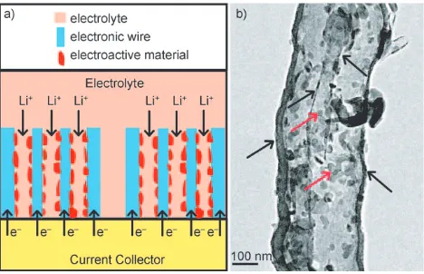
Herein, we propose the use of a nanoarchitectured electrode composed of an efficient mixed-conducting net-work (Figure 1 a), in which carbon tube-in-tube (CTIT) serves
as “electronic wire” which provides the electrons to the active materials and the specifically designed tube diameter of the CTIT allows for easy electrolyte access. Such a nanostructure provides both an electronic pathway and a lithium-ion pathway which are essential for a high rate rechargeable lithium battery. We also show that CTIT can be employed as a nanoreactor for the synthesis nanomaterials, by exploiting its multiple channels and the possibility of confining reagents within them. This concept was realized by the synthesis of V2O5/CTIT nanocomposites, which show significantly
improved Li insertion/extraction kinetics and a very high Figure 1. a) Schematic representation of the desired design based on an efficient mixed-conducting network. b) Typical TEM image of the V2O5/CTIT nanocomposites showing that most of the V2O5
nano-particles are encapsulated within CTIT. The V2O5nanoparticles
indi-cated by red arrows and CTIT indiindi-cated by black arrows. [*] Dr. Y.-S. Hu, Prof. Dr. J. Maier
Max-Planck-Institut fr Festkrperforschung Heisenbergstrasse 1, 70569 Stuttgart (Germany) E-mail: [email protected]
Dr. Y.-S. Hu
Beijing National Laboratory for Condensed Matter Physics, Institute of Physics, Chinese Academy of Sciences
Beijing 100080 (China) E-mail: [email protected]
X. Liu, Dr. J.-O. Mller, Prof. Dr. R. Schlgl, Dr. D. S. Su Fritz-Haber-Institut der Max-Planck-Gesellschaft Faradayweg 4-6, 14195 Berlin (Germany) E-mail: [email protected]
[**] The authors thank G. Gtz and A. Schulz for their technical support; Dr. R. Merkle for TG measurement; Drs. J. Jamnik, R. Dominko, and Y.-G. Guo for helpful discussions. The authors are indebted to the Max Planck Society and acknowledge support in the framework of the ENERCHEM project.
rate performance when used as a cathode material for lithium batteries.
Well-organized CTIT was successfully synthesized by a wet-chemical reorganization of the carbonaceous impurities in freshly prepared carbon nanotubes.[14]The morphology and
microstructure of freshly prepared carbon nanotubes and CTIT are shown in Figure S1 of the Supporting Information. The freshly prepared carbon nanotubes displayed the fish-boned microstructure combined with poorly graphitic carbon deposits (Figure S1b in the Supporting Information). After oxidation and reintegration treatment,[14]the carbon deposit
was exfoliated and a new tube with a thickness ranging from 10 to 20 nm formed along the long axis of the carbon nanotube as observed in the TEM images (Figures S1 c,d in the Supporting Information display the bi-tubular coaxial microstructure).
The fabrication mechanism of CTIT has been discussed elsewhere.[14]It suggests that the graphene sheets exfoliated
from the carbon deposits and impurities self-assemble along the carbon nanotube which acts as a template. Owing to the facile wet-chemical synthetic route, CTIT can be produced at low cost and on a large scale, which are prerequisites of large-scale applications. The multiple channels and surfaces of the CTIT are readily accessible for guest materials.
V2O5, whose various nanostructures (e.g. nanotubes,
nanorods, nanofibers, nanowires, nanobelts, and mesoporous structures) have been extensively investigated as a cathode material in lithium batteries,[5,10c,h,13,15–26]was selected in this
case to demonstrate the usefulness of the nanostructure design. By simply adding an aqueous solution of vanadate oxalate into the as-synthesized CTIT and subsequent heat treatment in air at 4008C for 2 h, a uniform coating of vanadium oxide nanoparticles was achieved. This coating can be clearly observed within the cylindrical and interval spaces of the CTIT and on the multiple surfaces by TEM (Figure 1 b and Figure S2 a,b in the Supporting Information). (A few V2O5nanoparticles were also formed on the external surface
of CTIT.) To confirm that most of the V2O5 nanoparticles
were encapsulated within the CTIT, we carried out TEM studies with varying tilt angle (see Figure S3 in the Supporting Information). These results show that most of the smaller nanoparticles are inside the CTIT, this is a result of the capillary force of the nanotubes. However, a few big particles were also found outside of CTIT. Clearly the driving force behind filling the CTIT with the vanadium precursor solution is surface interactions. Once the vanadium precursor is loaded into the CTIT, it can be converted into vanadium oxide nanoparticles by thermal treatment, a conversion that is favored by confinement in the tube space. The particle size is mostly around 30 nm. According to thermogravimetric (TG) measurements (not shown), the CTIT content is around 15 wt % in the nanocomposites. (Note that because only 70 % CTIT formed in synthetic process, V2O5nanoparticles were
also observed in the residual carbon nanotubes, see Fig-ure S2 c in the Supporting Information.) The results obtained indeed show that CTIT can be used as a nanoreactor to synthesize nanostructured inorganic compounds.
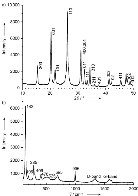
Figure 2 depicts the X-ray diffraction (XRD) and Raman spectrum of the nanocomposite. The XRD pattern indicates
the presence of crystalline V2O5and can be indexed according
to the orthogonal symmetry of V2O5 (space group: Pmmn
(No. 59),a=1.1516,b=0.3565,c=0.4372 nm; JCPDS card No. 41-1426).[5]It can be also observed that the Bragg peaks
are somewhat broadened, suggesting the presence of small crystalline particles. According to LeBails method, crystallite dimensions of about 30 nm can be deduced for the V2O5
nanoparticles, which is in good agreement with the TEM results. Raman spectrum indicates the coexistence of two phases, namely V2O5 and carbon, in the resulting
nano-composites.[25]
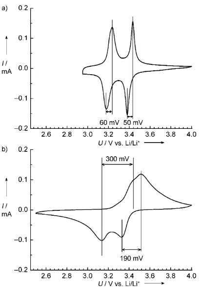
As there is close electrical contact between the two phases at the nanoscale level at many points along the wall of the CTIT (see HRTEM images in Figure S4 of the Supporting Information) and as the material is easily accessible to the electrolyte, the kinetics of Li insertion/extraction and the Li storage performance can be expected to be improved in this V2O5/CTIT nanocomposite over those of conventional
mate-rials. Cyclic voltammetry was used to investigate the Li insertion/extraction behavior. For comparison, commercially available micrometer-sized V2O5 was also tested (see
Fig-ure S5,6 in the Supporting Information). FigFig-ure 3 shows cyclic voltammograms (CVs) of both the V2O5/CTIT
nanocompo-site electrodes and of V2O5microparticle electrodes. The two
pairs of redox peaks at around 3.4 V and 3.2 V were observed for both electrodes, and are typically ascribed to the Figure 2. a) XRD pattern and b) Raman spectrum of the V2O5/CTIT
nanocomposites.
211
reversible reaction of lithium with crystalline V2O5in a
two-step electrochemical processes [Eq. (1) and (2)].[5, 13]
V2O5þ0:5 Li
þþ0
:5 e
ÐLi
0:5V2O5 ð1Þ
Li0:5V2O5þ0:5 Li
þþ0
:5 e
ÐLiV
2O5 ð2Þ
In the case of the V2O5/CTIT nanocomposite, the
differ-ences between the cathodic and anodic peaks for the redox reactions at around 3.4 and 3.2 V (so-called polarization) are 50 mV and 60 mV, respectively, which are much lower than those of microscale V2O5 (190 and 300 mV) at the same
experimental condition. In addition, the voltages of anodic peaks at around 3.4 and 3.2 V for the V2O5/CTIT
nano-composite are about 50 mV higher than those of microscale V2O5. These results clearly show that the kinetics of lithium
insertion/extraction in the V2O5/CTIT nanocomposite are
greatly improved by the close electrical contact between the nanoscale V2O5and CTIT.
Figure 4 a shows the first three cycles of galvanostatic discharge (Li insertion) and charge (Li extraction) curves of the V2O5/CTIT nanocomposite electrodes. Three plateaus at
3.4, 3.2, and 2.3 V can be observed in the discharge curves. The first two plateaus correspond to the reactions in Equations (1) and (2), which are in good agreement with the CV curves. The reversible capacity related to these processes is around 130 mA h g1, which is close to the
theoretical capacity of 147 mA h g1 for one lithium per
formula unit (V2O5). The capacity is also significantly higher
than for microscale V2O5.[26]The third plateau at 2.3 V can be
ascribed to a further lithium insertion into LiV2O5, which is
also highly reversible [Eq. (3)],[5, 13]
LiV2O5þ1 Liþþ1 e$Li2V2O5 ð3Þ
A total reversible capacity of about 280 mA h g1in the
voltage range of 2.0–4.0 V was obtained for the V2O5/CTIT
nanocomposite at a rate of C/2.5. Furthermore, in the charging process, nearly the same amount of lithium can be removed, corresponding to a coulombic efficiency of above 99 %. In addition, it was found that on cycling the capacity retention is good. Another property of this V2O5/CTIT
nanocomposite is the high rate capability. Results are shown in Figure 4 b in which rates of up to 40Chave been employed. The cell was first cycled atC/2.5 and, after 20 cycles, the rate was increased in stages to 40C. A specific charge capacity of around 265 mA h g1 with a coulombic efficiency of nearly
100 % was obtained at a rate of C/2.5 (58.8 mA g1) after
20 cycles; this value is lowered to 250 mA h g1 at 1C
(147 mA g1), 223 mA h g1at 4C(588 mA g1), 200 mA h g1
at 8C (1.176 A g1), 180 mA h g1 at 12
C (1.764 A g1),
160 mA h g1 at 16
C (2.352 A g1), 140 mA h g1 at 20
C
(2.940 A g1), and finally, 90 mA h g1 at 40C (5.880 A g1).
This rate capability is higher than those of carbon-coated V2O5 and other V2O5-based electrodes.[13, 15, 17] The
experi-Figure 3. Cyclic voltammograms of a) the V2O5/CTIT nanocomposite
and b) V2O5microparticles at a scan rate of 0.1 mVs1.
Figure 4. a) The first three cycles of galvanostatic discharge (Li inser-tion, voltage decreases)/charge (Li extracinser-tion, voltage increases) curves of the V2O5/CTIT nanocomposite electrode cycled at a current
density ofC/2.5 between voltage limits of 2.0–4.0 V in 1mLiPF6in
ethylene carbonate/dimethyl carbonate solution. b) Cycling and dis-charging/charging rate performance of the V2O5/CTIT nanocomposite
mental results obtained show that the mixed-conducting nanostructure favorably reduces the diffusion length for lithium ions and enables the high rate performance of lithium-based batteries.
In summary, an optimized nanostructured electrode design has been proposed. This nanoarchitecture is realized by the synthesis of the V2O5/CTIT nanocomposites which
show a significantly improved lithium-storage performance in terms of the kinetics for Li insertion/extraction, highly reversible lithium-storage capacity, good cycling perfor-mance, and high rate capability, making it a promising candidate as a cathode material in lithium-ion batteries. This design could also be extended to other cathode and anode electrode active materials that find application in energy-storage devices: for example, iron- and manganese-based phosphate cathodes.[10–12]
Experimental Section
Preparation of V2O5/CTIT nanocomposites:Details of the synthesis
of the CTIT has been reported elsewhere.[14]The CTIT supported
V2O5nanomaterial was prepared by the incipient wetness
impregna-tion method from ammonium metavanadate (NH4VO3) dissolved in
oxalic acid solution. The concentration of NH4VO3was 2.1 mol L1
and the molar ratio of NH4VO3to C2O4H2was 1:2. The solution was
introduced into the CTIT lumen by a wet chemistry using the capillary forces of nanotubes. After impregnation, the sample was dried in air at 808C overnight and then calcined at 4008C for 2 h. The loading amount of V2O5was approximately 80 wt %.
Structural Characterizations: A Philips TEM CM 200 Lab6 and Philips TEM/STEM CM 200 FEG transmission electron microscope were used to study the morphology and microstructure of the V2O5/
CTIT nanocomposites. The acceleration voltage is set to 200 kV. X-ray diffraction (XRD) patterns were recorded on a Philips instrument using CuKaradiation. Micro-Raman spectra were recorded on a Jobin
Yvon LabRam spectrometer using a 632.8 nm excitation laser line. Thermogravimetric analysis was carried out using a NETZSCH STA 449C (NETZSCH-Geraetebau GmbH Thermal Analysis) at a heating rate of 10 K min1under a mixture of N
2(5 mL)/O2(20 mL).
Electrochemical Characterizations: Electrochemical experiments were performed using two-electrode Swagelok-type cells. For prepar-ing workprepar-ing electrodes, a mixture of V2O5/CTIT nanocomposites or
pure V2O5, carbon black, and polyvinylidene fluoride (PVDF) at a
weight ratio of 80:10:10, was pasted on pure Al foil (99.6 %, Goodfellow). Glass fiber (GF/D) from Whatman was used as a separator. The electrolyte consists of a solution of 1m LiPF6 in
ethylene carbonate (EC)/dimethyl carbonate (DMC) (1:1, in volume) obtained from Ube Industries Ltd. Pure lithium foil (Aldrich) was used as counter electrode. The cells were assembled in an argon-filled glove box. The discharge and charge measurements were carried out at different current densities (herein 1C refers to 1 lithium per formula unit (V2O5) discharged/charged in 1 h) in the voltage range of
2.0–4.0 V on an Arbin MSTAT battery test system. The specific capacity of the V2O5/CTIT nanocomposites was calculated by using
the total mass of V2O5+CTIT. Cyclic voltammogram measurements
were performed on VoltaLab 80 electrochemical workstation at a scan rate of 0.1 mV s1.
Received: June 22, 2008 Revised: September 30, 2008 Published online: November 28, 2008
.
Keywords: electrochemistry · lithium-ion batteries · nanoreactors · nanostructures · nanotubes · V2O5[1] a) H. S. Zhou, D. L. Li, M. Hibino, I. Honma,Angew. Chem. 2005,117, 807 – 812;Angew. Chem. Int. Ed.2005,44, 797 – 802; b) K. X. Wang, M. D. Wei, M. A. Morris, H. S. Zhou,Adv. Mater. 2007,19, 3016 – 3020.
[2] A. S. Aric, P. G. Bruce, B. Scrosati, J. M. Tarascon, W. van Schalkwijk,Nat. Mater.2005,4, 366 – 377.
[3] a) J. Hassoun, S. Panero, P. Simon, P. L. Taberna, B. Scrosati, Adv. Mater.2007,19, 1632 – 1635; b) G. Derrien, J. Hassoun, S. Panero, B. Scrosati,Adv. Mater.2007,19, 2336 – 2340.
[4] A. M. Cao, J. S. Hu, H. P. Liang, L. J. Wan,Angew. Chem.2005, 117, 4465 – 4469;Angew. Chem. Int. Ed.2005,44, 4391 – 4395. [5] N. S. Ergang, J. C. Lytle, K. T. Lee, S. M. Oh, W. H. Smyrl, A.
Stein,Adv. Mater.2006,18, 1750 – 1753.
[6] a) J. Maier,Nat. Mater.2005,4, 805 – 815; b) Y.-S. Hu, Y.-G. Guo, Gaberscek, J. Jamnik, J. Maier, Adv. Mater. 2007, 19, 1963 – 1966; g) Y. S. Hu, R. D. Cakan, M. M. Titirici, J. O. Mller, R. Schlgl, M. Antonietti, J. Maier,Angew. Chem.2008,120, 1669 – 1673; Angew. Chem. Int. Ed. 2008, 47, 1645 – 1649; h) P. G. Bruce, B. Scrosati, J.-M. Tarascon, Angew. Chem.2008, 120, 2972 – 2989;Angew. Chem. Int. Ed.2008,47, 2930 – 2946. [7] a) L. Kavan, D. Fattakhova, P. Krtil,J. Electrochem. Soc.1999,
146, 1375 – 1379; b) E. Baudrin, S. Cassaignon, M. Koelsch, J. P. Jolivet, L. Dupont, J. M. Tarascon,Electrochem. Commun.2007, 9, 337 – 342; c) C. H. Jiang, I. Honma, T. Kudo, H. S. Zhou, Electrochem. Solid-State Lett.2007,10, A127 – A129.
[8] a) J. Y. Luo, J. J. Zhang, Y. Y. Xia,Chem. Mater.2006,18, 5618 – 5623; b) F. Jiao, P. G. Bruce,Adv. Mater.2007,19, 657 – 660. [9] a) S. H. Ng, J. Wang, D. Wexler, K. Konstantinov, Z. P. Guo,
H. K. Liu,Angew. Chem.2006,118, 7050 – 7053;Angew. Chem. Int. Ed.2006, 45, 6896 – 6899; b) S. Y. Chew, Z. P. Guo, J. Z. Wang, J. Chen, P. Munroe, S. H. Ng, L. Zhao, H. K. Liu, Electrochem. Commun.2007,9, 941 – 946; c) J. O. Besenhard, J. Yang, M. Winter,J. Power Sources1997,68, 87 – 90; d) J. Shu, H. Li, R. Yang, Y. Shi, X. Huang,Electrochem. Commun.2006,8, 51 – 54; e) T. Jiang, S. C. Zhang, X. P. Qiu, W. T. Zhu, L. Q. Chen, Electrochem. Commun.2007,9, 930 – 934; f) A. M. Wilson, J. R. Dahn,J. Electrochem. Soc.1995,142, 326 – 332.
[10] a) P. L. Taberna, S. Mitra, P. Poizot, P. Simon, J. M. Tarascon, Nat. Mater.2006,5, 567 – 573; b) K. H. Reiman, K. M. Brace, T. J. Gordon-Smith, I. Nandhakumar, G. S. Attard, J. R. Owen, Electrochem. Commun.2006,8, 517 – 522; c) C. R. Sides, N. C. Li, C. J. Patrissi, B. Scrosati, C. R. Martin,MRS Bull.2002,27, 604 – 607; d) C. R. Sides, F. Croce, V. Y. Young, C. R. Martin, B. Scrosati, Electrochem. Solid-State Lett. 2005, 8, A484 – A487; e) K. S. Park, S. B. Schougaard, J. B. Goodenough,Adv. Mater. 2007,19, 848 – 851; f) H. Huang, S. C. Yin, T. Kerr, N. Taylor, L. F. Nazar,Adv. Mater.2002,14, 1525 – 1528; g) R. Dominko, M. Bele, J. M. Goupil, M. Gaberseek, D. Hanzel, L. Arcon, J. Jamnik,Chem. Mater.2007,19, 2960 – 2969; h) J. S. Sakamoto, B. Dunn,J. Mater. Chem.2002,12, 2859 – 2861.
[11] a) N. Ravet, Y. Chouinard, J. F. Magnan, S. Besner, M. Gauthier, M. Armand, J. Power Sources2001, 97–98, 503 – 507; b) P. S. Herle, B. Ellis, N. Coombs, L. F. Nazar,Nat. Mater.2004,3, 147 – 152; c) R. Dominko, M. Bele, M. Gaberscek, M. Remskar, D. Hanzel, J. M. Goupil, S. Pejovnik, J. Jamnik,J. Power Sources 2006, 153, 274 – 280; d) M. Gaberscek, J. Jamnik, Solid State Ionics2006,177, 2647 – 2651; e) L. J. Fu, H. Liu, H. P. Zhang, C. Li, T. Zhang, Y. P. Wu, R. Holze, H. Q. Wu, Electrochem. Commun.2006,8, 1 – 4.
[12] B. L. Ellis, W. R. M. Makahnouk, Y. Makimura, K. Toghill, L. F. Nazar,Nat. Mater.2007,6, 749 – 753.
213
[13] A. Odani, V. G. Pol, S. V. Pol, M. Koltypin, A. Gedanken, D. Aurbach,Adv. Mater.2006,18, 1431 – 1436.
[14] Z. P. Zhu, D. S. Su, G. Weinberg, R. Schlgl,Nano Lett.2004,4, 2255 – 2259.
[15] F. Zhang, S. Passerini, B. B. Owens, W. H. Smyrl,Electrochem. Solid-State Lett.2001,4, A221 – A223.
[16] W. Chen, Q. Xu, Y. S. Hu, L. Q. Mai, Q. Y. Zhu,J. Mater. Chem. 2002,12, 1926 – 1929.
[17] P. Liu, S. H. Lee, C. E. Tracy, Y. F. Yan, J. A. Turner,Adv. Mater. 2002,14, 27 – 30.
[18] J. S. Sakamoto, B. Dunn,J. Electrochem. Soc.2002,149, A26 – A30.
[19] C. R. Sides, C. R. Martin,Adv. Mater.2005,17, 125 – 128. [20] Y. Wang, K. Takahashi, K. Lee, G. Z. Cao,Adv. Funct. Mater.
2006,16, 1133 – 1144.
[21] C. Navone, J. P. Pereira-Ramos, R. Baddour-Hadjean, R. Salot, J. Electrochem. Soc.2006,153, A2287 – A2293.
[22] N. Liu, H. Li, J. Jiang, X. J. Huang, L. Q. Chen,J. Phys. Chem. B 2006,110, 10341 – 10347.
[23] X. X. Li, W. Y. Li, H. Ma, J. Chen,J. Electrochem. Soc.2007,154, A39 – A42.
[24] C. K. Chan, H. Peng, R. D. Twesten, K. Jarausch, X. F. Zhang, Y. Cui,Nano Lett.2007,7, 490 – 495.
[25] R. Baddour-Hadjean, E. Raekelboom, J. P. Pereira-Ramos, Chem. Mater.2006,18, 3548 – 3556.
[26] a) A. Shimizu, T. Tsumura, M. Inagaki,Solid State Ionics1993, 63–65, 479 – 483; b) N. Kumagain, K. Tanno, T. Nakajima, N. Watanabe,Electrochim. Acta1983,28, 17 – 22.