CORROSION AND
CORROSION CONTROL
An Introduction
to Corrosion Science
and Engineering
FOURTH EDITION
R. Winston Revie
Senior Research Scientist CANMET Materials Technology Laboratory Natural Resources CanadaHerbert H. Uhlig
Former Professor Emeritus Department of Materials Science and Engineering Massachusetts Institute of TechnologyCORROSION AND
CORROSION CONTROL
An Introduction
to Corrosion Science
and Engineering
FOURTH EDITION
R. Winston Revie
Senior Research Scientist CANMET Materials Technology Laboratory Natural Resources CanadaHerbert H. Uhlig
Former Professor Emeritus Department of Materials Science and Engineering Massachusetts Institute of TechnologyPublished by John Wiley & Sons, Inc., Hoboken New Jersey Published simultaneously in Canada
No part of this publication may be reproduced, stored in a retrieval system, or transmitted in any form or by any means, electronic, mechanical, photocopying, recording, scanning, or otherwise, except as permitted under Section 107 or 108 of the 1976 United States Copyright Act, without either the prior written permission of the Publisher, or authorization through payment of the appropriate per-copy fee to the Copyright Clearance Center, Inc., 222 Rosewood Drive, Danvers, MA 01923, (978) 750-8400, fax (978)750-4470, or on the web at www.copyright.com. Requests to the Publisher for permission should be addressed to the Permissions Department, John Wiley & Sons, Inc., 111 River Street, Hoboken, NJ 07030, (201) 748-6011, fax (201) 748-6008, or online at http://www.wiley.com/go/permission.
Limit of Liability/Disclaimer of Warranty: While the publisher and author have used their best efforts in preparing this book, they make no representations or warranties with respect to the accuracy or completeness of the contents of this book and specifi cally disclaim any implied warranties of merchantability or fi tness for a particular purpose. No warranty may be created or extended by sales representatives or written sales materials. The advice and strategies contained herein may not be suitable for your situation. You should consult with a professional where appropriate. Neither the publisher nor author shall be liable for any loss of profi t or any other commercial damages, including but not limited to special, incidental, consequential, or other damages.
For general information on our other products and services or for technical support, please contact our Customer Care Department within the United States at (800) 762-2974, outside the United States at (317) 572-3993 or fax (317) 572-4002.
Wiley also publishes its books in a variety of electronic formats. Some content that appears in print may not be available in electronic formats. For more information about Wiley products, visit our web site at www.wiley.com.
Library of Congress Cataloging-in-Publication Data:
Uhlig, Herbert Henry, 1907–
Corrosion and corrosion control : an introduction to corrosion science and engineering / Herbert H. Uhlig, R. Winston Revie.—4th ed.
p. cm.
Includes bibliographical references and index. ISBN 978-0-471-73279-2 (cloth)
1. Corrosion and anti-corrosives. I. Revie, R. Winston (Robert Winston), 1944– II. Title. TA462.U39 2008
620.1′1223–dc22
2007041578 Printed in the United States of America
CONTENTS
v Preface xvii
1
DEFINITION AND IMPORTANCE OF CORROSION 11.1 Defi nition of Corrosion 1
1.1.1 Corrosion Science and Corrosion Engineering 1
1.2 Importance of Corrosion 2
1.3 Risk Management 5
1.4 Causes of Corrosion 6
1.4.1 Change in Gibbs Free Energy 6
1.4.2 Pilling–Bedworth Ratio 6
References 6
General References 7
Problems 7
2
ELECTROCHEMICAL MECHANISMS 92.1 The Dry-Cell Analogy and Faraday’s Law 9
2.2 Defi nition of Anode and Cathode 11
2.3 Types of Cells 13
2.4 Types of Corrosion Damage 15
References 18
General References 19
Problems 19
3
THERMODYNAMICS: CORROSION TENDENCY ANDELECTRODE POTENTIALS 21
3.1 Change of Gibbs Free Energy 21
3.2 Measuring the Emf of a Cell 22
3.6 Measurement of pH 28 3.7 The Oxygen Electrode and Differential Aeration Cell 28
3.8 The Emf and Galvanic Series 30
3.9 Liquid Junction Potentials 33
3.10 Reference Electrodes 34
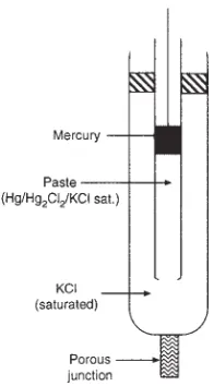
3.10.1 Calomel Reference Electrode 35
3.10.2 Silver–Silver Chloride Reference Electrode 36 3.10.3 Saturated Copper–Copper Sulfate Reference
Electrode 36 References 37
General References 38
Problems 38
Answers to Problems 40
4
THERMODYNAMICS: POURBAIX DIAGRAMS 434.1 Basis of Pourbaix Diagrams 43
4.2 Pourbaix Diagram for Water 44
4.3 Pourbaix Diagram for Iron 45
4.4 Pourbaix Diagram for Aluminum 47
4.5 Pourbaix Diagram for Magnesium 48
4.6 Limitations of Pourbaix Diagrams 49
References 50
General References 50
Problems 50
Answers to Problem 51
5
KINETICS: POLARIZATION AND CORROSION RATES 535.1 Polarization 53
5.2 The Polarized Cell 54
5.3 How Polarization Is Measured 56
5.3.1 Calculation of IR Drop in an Electrolyte 58
5.4 Causes of Polarization 58
5.5 Hydrogen Overpotential 63
5.6 Polarization Diagrams of Corroding Metals 66
5.7 Infl uence of Polarization on Corrosion Rate 68 5.8 Calculation of Corrosion Rates from Polarization Data 71
5.9 Anode–Cathode Area Ratio 73
CONTENTS vii
5.11 Theory of Cathodic Protection 77
References 79
General References 80
Problems 80
Answers to Problems 82
6
PASSIVITY 836.1 Defi nition 83
6.2 Characteristics of Passivation and the Flade Potential 84
6.3 Behavior of Passivators 88
6.3.1 Passivation of Iron by HNO
3 89
6.4 Anodic Protection and Transpassivity 90
6.5 Theories of Passivity 92
6.5.1 More Stable Passive Films with Time 95
6.5.2 Action of Chloride Ions and Passive–Active Cells 96
6.6 Critical Pitting Potential 97
6.7 Critical Pitting Temperature 99
6.8 Passivity of Alloys 100
6.8.1 Nickel–Copper Alloys 103
6.8.2 Other Alloys 108
6.9 Effect of Cathodic Polarization and Catalysis 108 References 109
General References 111
Problems 112
Answers to Problems 113
7
IRON AND STEEL 1157.1 Introduction 115
7.2 Aqueous Environments 116
7.2.1 Effect of Dissolved Oxygen 116
7.2.2 Effect of Temperature 120
7.2.3 Effect of pH 120
7.2.4 Effect of Galvanic Coupling 127
7.2.5 Effect of Velocity on Corrosion in Natural Waters 129
7.2.6 Effect of Dissolved Salts 131
7.3 Metallurgical Factors 138
7.3.1 Varieties of Iron and Steel 138
7.3.3 Effect of Heat Treatment 142
7.4 Steel Reinforcements in Concrete 143
References 145
General References 147
Problems 147
Answers to Problems 148
8
EFFECT OF STRESS 1498.1 Cold Working 149
8.2 Stress-Corrosion Cracking 150
8.2.1 Iron and Steel 151
8.3 Mechanism of Stress-Corrosion Cracking of Steel and
Other Metals 156
8.3.1 Electrochemical Dissolution 157
8.3.2 Film-Induced Cleavage 158
8.3.3 Adsorption-Induced Localized Slip 158
8.3.4 Stress Sorption 158
8.3.5 Initiation of Stress-Corrosion Cracking and
Critical Potentials 161
8.3.6 Rate of Crack Growth (Fracture Mechanics) 162
8.4 Hydrogen Damage 166
8.4.1 Mechanism of Hydrogen Damage 167
8.4.2 Effect of Metal Flaws 170
8.5 Radiation Damage 172
8.6 Corrosion Fatigue 173
8.6.1 Critical Minimum Corrosion Rates 177
8.6.2 Remedial Measures 178
8.6.3 Mechanism of Corrosion Fatigue 179
8.7 Fretting Corrosion 180
8.7.1 Mechanism of Fretting Corrosion 182
8.7.2 Remedial Measures 184
References 185
General References 188
Problems 190
Answers to Problems 190
9
ATMOSPHERIC CORROSION 1919.1 Introduction 191
CONTENTS ix
9.3 Corrosion-Product Films 192
9.4 Factors Infl uencing Corrosivity of the Atmosphere 195
9.4.1 Particulate Matter 196
9.4.2 Gases in the Atmosphere 197
9.4.3 Moisture (Critical Humidity) 199
9.5 Remedial Measures 201
References 202
General References 203
Problems 204
10
CORROSION IN SOILS 20510.1 Introduction 205
10.2 Factors Affecting the Corrosivity of Soils 206
10.3 Bureau of Standards Tests 207
10.3.1 Pitting Characteristics 208
10.4 Stress-Corrosion Cracking 210
10.5 Remedial Measures 211
References 212
General References 212
11
OXIDATION 21511.1 Introduction 215
11.2 Initial Stages 216
11.3 Thermodynamics of Oxidation: Free
Energy–Temperature Diagram 218
11.4 Protective and Nonprotective Scales 218
11.4.1 Three Equations of Oxidation 220
11.5 Wagner Theory of Oxidation 223
11.6 Oxide Properties and Oxidation 224
11.7 Galvanic Effects and Electrolysis of Oxides 227
11.8 Hot Ash Corrosion 229
11.9 Hot Corrosion 229
11.10 Oxidation of Copper 230
11.10.1 Internal Oxidation 231
11.10.2 Reaction with Hydrogen (“Hydrogen Disease”) 231
11.11 Oxidation of Iron and Iron Alloys 232
11.12 Life Test for Oxidation-Resistant Wires 233
11.13 Oxidation-Resistant Alloys 234
11.13.2 Chromium–Iron Alloys 235
11.13.3 Chromium–Aluminum–Iron Alloys 236
11.13.4 Nickel and Nickel Alloys 236
11.13.5 Furnace Windings 237
References 237
General References 239
Problems 239
Answers to Problems 240
12
STRAY-CURRENT CORROSION 24112.1 Introduction 241
12.2 Sources of Stray Currents 242
12.3 Quantitative Damage by Stray Currents 244
12.4 Detection of Stray Currents 245
12.5 Soil-Resistivity Measurement 246
12.6 Means for Reducing Stray-Current Corrosion 246 References 247
General References 247
Problems 247
Answers to Problems 249
13
CATHODIC PROTECTION 25113.1 Introduction 251
13.2 Brief History 252
13.3 How Applied 253
13.3.1 Sacrifi cial Anodes 254
13.4 Combined Use with Coatings 255
13.5 Magnitude of Current Required 257
13.6 Anode Materials and Backfi ll 258
13.6.1 Overprotection 259
13.7 Criteria of Protection 260
13.7.1 Potential Measurements 260
13.7.2 Doubtful Criteria 262
13.7.3 Position of Reference Electrode 262
13.8 Economics of Cathodic Protection 263
13.9 Anodic Protection 263
References 265
CONTENTS xi
Problems 266
Answers to Problems 267
14
METALLIC COATINGS 26914.1 Methods of Application 269
14.2 Classifi cation of Coatings 271
14.3 Specifi c Metal Coatings 272
14.3.1 Nickel Coatings 272
14.3.2 Lead Coatings 274
14.3.3 Zinc Coatings 274
14.3.4 Cadmium Coatings 276
14.3.5 Tin Coatings 277
14.3.6 Chromium-Plated Steel for Containers 279
14.3.7 Aluminum Coatings 280
References 281
General References 282
15
INORGANIC COATINGS 28515.1 Vitreous Enamels 285
15.2 Portland Cement Coatings 286
15.3 Chemical Conversion Coatings 286
References 288
General References 288
16
ORGANIC COATINGS 28916.1 Introduction 289
16.2 Paints 289
16.3 Requirements for Corrosion Protection 291
16.4 Metal Surface Preparation 293
16.4.1 Cleaning All Dirt, Oils, and Greases from
the Surface 293
16.4.2 Complete Removal of Rust and Mill Scale 294
16.5 Applying Paint Coatings 295
16.5.1 Wash Primer 296
16.5.2 Painting of Aluminum and Zinc 296
16.6 Filiform Corrosion 296
16.6.1 Theory of Filiform Corrosion 298
References 300
General References 301
17
INHIBITORS AND PASSIVATORS 30317.1 Introduction 303
17.2 Passivators 304
17.2.1 Mechanism of Passivation 304
17.2.2 Applications of Passivators 308
17.3 Pickling Inhibitors 310
17.3.1 Applications of Pickling Inhibitors 312
17.4 Slushing Compounds 313
17.5 Vapor-Phase Inhibitors 313
17.5.1 Inhibitor to Reduce Tarnishing of Copper 314 References 315
General References 316
18
TREATMENT OF WATER AND STEAM SYSTEMS 31718.1 Deaeration and Deactivation 317
18.2 Hot- and Cold-Water Treatment 321
18.2.1 Cooling Waters 322
18.3 Boiler-Water Treatment 323
18.3.1 Boiler Corrosion 323
18.3.2 Boiler-Water Treatment for Corrosion Control 326
18.3.3 Mechanisms 328
References 330
General References 331
19
ALLOYING FOR CORROSION RESISTANCE;STAINLESS STEELS 333
19.1 Introduction 333
19.2 Stainless Steels 335
19.2.1 Brief History 336
19.2.2 Classes and Types 337
19.2.3 Intergranular Corrosion 343
19.2.4 Pitting and Crevice Corrosion 350
19.2.5 Stress-Corrosion Cracking and Hydrogen Cracking 354 19.2.6 Cracking of Sensitized Austenitic Alloys in
CONTENTS xiii
19.2.7 Galvanic Coupling and General Corrosion
Resistance 361 References 362
General References 365
20
COPPER AND COPPER ALLOYS 36720.1 Copper 367
20.1.1 Corrosion in Natural Waters 369
20.2 Copper Alloys 371
20.2.1 Copper–Zinc Alloys (Brasses) 371
20.2.2 Dealloying/Dezincifi cation 372
20.2.3 Stress-Corrosion Cracking (Season Cracking) 374 20.2.4 Condenser Tube Alloys Including
Copper–Nickel Alloys 378
References 379
General References 381
Problems 381
Answers to Problems 381
21
ALUMINUM AND ALUMINUM ALLOYS 38321.1 Aluminum 383
21.1.1 Clad Alloys 384
21.1.2 Corrosion in Water and Steam 384
21.1.3 Effect of pH 387
21.1.4 Corrosion Characteristics 388
21.1.5 Galvanic Coupling 392
21.2 Aluminum Alloys 393
21.2.1 Stress-Corrosion Cracking 394
References 396
General References 397
22
MAGNESIUM AND MAGNESIUM ALLOYS 39922.1 Introduction 399
22.2 Magnesium 399
22.3 Magnesium Alloys 400
22.3.1 Stress-Corrosion Cracking 402
22.3.2 Coatings 403
References 405
General References 405
23
NICKEL AND NICKEL ALLOYS 40723.1 Introduction 407
23.2 Nickel 408
23.3 Nickel Alloys 411
23.3.1 General Behavior 411
23.3.2 Ni–Cu System: Alloy 400—70% Ni, 30% Cu 414 23.3.3 Ni–Cr–Fe System: Alloy 600—76% Ni, 16% Cr,
7% Fe 414
23.3.4 Ni–Mo System: Alloy B—60% Ni, 30% Mo,
5% Fe 415
23.3.5 Ni–Cr–Fe–Mo–Cu System: Alloy G—Ni, 22%
Cr, 20% Fe, 6.5% Mo, 2% Cu 416
23.3.6 Ni–Cr–Mo System: Alloy C—54% Ni, 15% Cr,
16% Mo, 4% W, 5% Fe 416
23.3.7 Ni–Fe–Cr System: Alloy 825—Ni, 31% Fe, 22% Cr 417 References 417
General References 418
24
COBALT AND COBALT ALLOYS 41924.1 Introduction 419
24.2 Cobalt Alloys 420
References 423
General References 423
25
TITANIUM 42525.1 Titanium 425
25.2 Titanium Alloys 427
25.3 Pitting and Crevice Corrosion 429
25.4 Intergranular Corrosion and Stress-Corrosion Cracking 430 References 432
General References 434
Problem 434
26
ZIRCONIUM 43526.1 Introduction 435
CONTENTS xv
26.3 Behavior in Hot Water and Steam 437
References 439
General References 440
27
TANTALUM 44127.1 Introduction 441
27.2 Corrosion Behavior 441
References 443
General Reference 443
28
LEAD 44528.1 Introduction 445
28.2 Corrosion Behavior of Lead and Lead Alloys 446
28.2.1 Lead–Acid Battery 447
28.3 Summary 448
References 449
General References 449
29
APPENDIX 45129.1 Activity and Activity Coeffi cients of Strong
Electrolytes 451 29.2 Derivation of Stern–Geary Equation for Calculating
Corrosion Rates from Polarization Data Obtained at
Low Current Densities 456
29.2.1 The General Equation 458
29.3 Derivation of Equation Expressing the Saturation Index
of a Natural Water 461
29.4 Derivation of Potential Change along a Cathodically
Protected Pipeline 467
29.5 Derivation of the Equation for Potential Drop along the Soil Surface Created by Current Entering or
Leaving a Buried Pipe 469
29.6 Derivation of the Equation for Determining Resistivity
of Soil by Four-Electrode Method 470
29.7 Derivation of the Equation Expressing Weight Loss by
Fretting Corrosion 471
29.8 Conversion Factors 474
29.8.1 Additional Conversion Factors 475
29.8.2 Current Density Equivalent to a Corrosion Rate
29.9 Standard Potentials 476
29.10 Notation and Abbreviations 476
References 478
xvii
PREFACE
The three main global challenges for the twenty - fi rst century are energy, water, and air — that is, suffi cient energy to ensure a reasonable standard of living, clean water to drink, and clean air to breathe. The ability to manage corrosion is a central part of using materials effectively and effi ciently to meet these challenges. For example, oil and natural gas are transmitted across continents using high - pressure steel pipelines that must operate for decades without failure, so that neither the groundwater nor the air is unnecessarily polluted. In design, operation, and maintenance of nuclear power plants, management of corrosion is critical. The reliability of materials used in nuclear waste dis-posal must be suffi cient so that that the safety of future generations is not compromised.
Materials reliability is becoming ever more important in our society, particu-larly in view of the liability issues that develop when reliability is not assured, safety is compromised, and failure occurs. Notwithstanding the many years over which university, college, and continuing education courses in corrosion have been available, high - profi le corrosion failures continue to take place. Although the teaching of corrosion should not be regarded as a dismal failure, it has cer-tainly not been a stellar success providing all engineers and technologists a basic minimum “ literacy level ” in corrosion that would be suffi cient to ensure reliabil-ity and prevent failures.
Senior management of some organizations has adopted a policy of “ zero failures ” or “ no failures. ” In translating this management policy into reality, so that “ zero ” really does mean “ zero ” and “ no ” means “ no, ” engineers and others manage corrosion using a combination of well - established strategies, innovative approaches, and, when necessary, experimental trials.
when different materials form a couple, but also when materials that are nomi-nally the same are coupled. In this edition, some new numerical problems have been added, and the problems are integrated into the book by presenting them at the ends of the chapters.
Since the third edition of this book was published, there have been many advances in corrosion, including advances in knowledge, advances in alloys for application in aggressive environments, and advances of industry in response to public demand. For example, consumer demand for corrosion protection of auto-mobiles has led to a revolution of materials usage in the automotive industry. For this reason, and also because many students have a fascination with cars, numer-ous examples throughout this book illustrate advances that have been made in corrosion engineering of automobiles. Advances in protecting cars and trucks from corrosion must also be viewed in the context of reducing vehicle weight by using magnesium, aluminum, and other lightweight materials in order to decrease energy usage (increase the miles per gallon, or kilometers per liter, of gasoline) and reduce greenhouse gas emissions.
Although the basic organization of the book is unchanged from the previous edition, there is in this edition a separate chapter on Pourbaix diagrams, very useful tools that indicate the thermodynamic potential – pH domains of corrosion, passivity, and immunity to corrosion. A consideration of the relevant Pourbaix diagrams can be a useful starting point in many corrosion studies and investiga-tions. As always in corrosion, as well as in this book, there is the dual importance of thermodynamics (In which direction does the reaction go? Chapters 3 and 4 ) and kinetics (How fast does it go? Chapter 5 ).
After establishing the essential basics of corrosion in the fi rst fi ve chapters, the next 23 chapters expand upon the fundamentals in specifi c systems and appli-cations and discuss strategies for protection. There are separate chapters on alu-minum (Chapter 21 ), magnesium (Chapter 22 ), and titanium (Chapter 25 ) to provide more information on these metals and their alloys than in the previous editions. Throughout this book, environmental concerns and regulations are pre-sented in the context of their impact on corrosion and its control — for example, the EPA Lead and Copper rule enacted in the United States in 1991. The indus-trial developments in response to the Clean Air Act, enacted in 1970, have reduced air pollution in the United States, with some effect on atmospheric cor-rosion (Chapter 9 ). To meet the requirements of environmental regulations and reduce the use of organic solvents, compliant coatings have been developed (Chapter 16 ).
PREFACE xix
many alloys have been developed and are commercially available, the contribu-tions of individual elements to endow alloys with unique properties that are valuable for specifi c applications are discussed. Throughout the book, there are numerous references to further sources of information, including handbooks, other books, reviews, and papers in journals. At the end of each chapter, there is a list of “ General References ” pertinent to that chapter, and most of these were published in 2000 and later.
This edition includes introductory discussions of risk (Chapter 1 ), AC imped-ance measurements (Chapter 5 ), Ellingham diagrams (Chapter 11 ), and, through-out the book, discussions of new alloys that have been developed to meet demands for increasing reliability notwithstanding the increased structural lifetimes that are being required in corrosive environments of ever - increasing severity. Perhaps nowhere are the demands for reliability more challenging than in nuclear reactors, discussed in Chapters 8 and 26 . In the discussion of stainless steels (Chapter 19 ), the concept of critical pitting temperature (CPT) is introduced, as well as the infor-mation on critical pitting potential (CPP). The important problem of corrosion of rebar (reinforced steel in concrete) is discussed in Chapter 7 on iron and steel.
In addition to new technologies and new materials for managing corrosion, new tools for presenting books have become available; hence, this book is being published as an electronic book, as well as in the traditional print format. An instructor ’ s manual is also being prepared.
Experience has been invaluable in using the book in a corrosion course in the Department of Mechanical and Aerospace Engineering at Carleton Univer-sity in Ottawa, which Glenn McRae and I developed along with other members of the Canadian National Capital Section of NACE International.
It would be a delight for me to hear from readers of this book, with their suggestions and ideas for future editions.
I would like to acknowledge my many friends and colleagues at the CANMET Materials Technology Laboratory, with whom it has been my privilege to work for the past nearly 30 years. I would also like to thank the many organizations and individuals who have granted permission to use copyright material; acknowl-edgments for specifi c material are provided throughout the book. In addition, I would like to thank Bob Esposito and his staff at John Wiley & Sons, Inc. for their encouragement with this book and also with the Wiley Series in Corrosion.
I would like to thank the Uhlig family for their generosity and hospitality during fi ve decades, beginning when I was a student in the M.I.T. Corrosion Laboratory in the 1960s and 1970s. In particular, I would like to acknowledge Mrs. Greta Uhlig, who continues to encourage initiatives in corrosion education in memory of the late Professor Herbert H. Uhlig (1907 – 1993).
Lastly, I would like to quote from the Preface of the fi rst edition of this book:
natural resources caused by metal deterioration, it will have fulfi lled the author ’ s major objective.
Indeed, this remains the main objective today.
Ottawa, Canada R. W inston R evie
1
1
Corrosion and Corrosion Control, by R. Winston Revie and Herbert H. Uhlig
Copyright © 2008 John Wiley & Sons, Inc.
DEFINITION AND IMPORTANCE
OF CORROSION
1.1 DEFINITION OF CORROSION
Corrosion is the destructive attack of a metal by chemical or electrochemical reaction with its environment. Deterioration by physical causes is not called cor-rosion, but is described as ecor-rosion, galling, or wear. In some instances, chemical attack accompanies physical deterioration, as described by the following terms: corrosion – erosion, corrosive wear, or fretting corrosion. Nonmetals are not included in this defi nition of corrosion. Plastics may swell or crack, wood may split or decay, granite may erode, and Portland cement may leach away, but the term corrosion, in this book, is restricted to chemical attack of metals.
“ Rusting ” applies to the corrosion of iron or iron - base alloys with formation of corrosion products consisting largely of hydrous ferric oxides. Nonferrous metals, therefore, corrode, but do not rust.
1.1.1 Corrosion Science and Corrosion Engineering
electrochemistry is also important. Furthermore, since structure and composition of a metal often determine corrosion behavior, the student should be familiar with the fundamentals of physical metallurgy as well.
The corrosion scientist studies corrosion mechanisms to improve (a) the understanding of the causes of corrosion and (b) the ways to prevent or at least minimize damage caused by corrosion. Thecorrosion engineer , on the other hand, applies scientifi c knowledge to control corrosion. For example, the corrosion engineer uses cathodic protection on a large scale to prevent corrosion of buried pipelines, tests and develops new and better paints, prescribes proper dosage of corrosion inhibitors, or recommends the correct coating. The corrosion scientist, in turn, develops better criteria of cathodic protection, outlines the molecular structure of chemical compounds that behave best as inhibitors, synthesizes corrosion - resistant alloys, and recommends heat treatment and compositional variations of alloys that will improve their performance. Both the scientifi c and engineering viewpoints supplement each other in the diagnosis of corrosion damage and in the prescription of remedies.
1.2 IMPORTANCE OF CORROSION
The three main reasons for the importance of corrosion are: economics, safety, and conservation. To reduce the economic impact of corrosion, corrosion engi-neers, with the support of corrosion scientists, aim to reduce material losses, as well as the accompanying economic losses, that result from the corrosion of piping, tanks, metal components of machines, ships, bridges, marine structures, and so on. Corrosion can compromise the safety of operating equipment by causing failure (with catastrophic consequences) of, for example, pressure vessels, boilers, metallic containers for toxic chemicals, turbine blades and rotors, bridges, airplane components, and automotive steering mechanisms. Safety is a critical consideration in the design of equipment for nuclear power plants and for dis-posal of nuclear wastes. Loss of metal by corrosion is a waste not only of the metal, but also of the energy, the water, and the human effort that was used to produce and fabricate the metal structures in the fi rst place. In addition, rebuild-ing corroded equipment requires further investment of all these resources — metal, energy, water, and human.
steel where the latter has adequate mechanical properties but not suffi cient cor-rosion resistance; there are also the costs of galvanizing or nickel plating of steel, of adding corrosion inhibitors to water, and of dehumidifying storage rooms for metal equipment.
The economic factor is a very important motivation for much of the current research in corrosion. Losses sustained by industry and by governments amount to many billions of dollars annually, approximately $ 276 billion in the United States, or 3.1% of the Gross Domestic Product (GDP), according to a recent study [1] . It has been estimated that about 25 – 30% of this total could be avoided if currently available corrosion technology were effectively applied [1] .
Studies of the cost of corrosion to Australia, Great Britain, Japan, and other countries have also been carried out. In each country studied, the cost of corro-sion is approximately 3 – 4 % of the Gross National Product [2] .
Indirect losses are more diffi cult to assess, but a brief survey of typical losses of this kind compels the conclusion that they add several billion dollars to the direct losses already outlined. Examples of indirect losses are as follows:
1. Shutdown. The replacement of a corroded tube in an oil refi nery may cost a few hundred dollars, but shutdown of the unit while repairs are under-way may cost $ 50,000 or more per hour in lost production. Similarly, replacement of corroded boiler or condenser tubes in a large power plant may require $ 1,000,000 or more per day for power purchased from inter-connected electric systems to supply customers while the boiler is down. Losses of this kind cost the electrical utilities in the United States tens of millions of dollars annually.
2. Loss of Product. Losses of oil, gas, or water occur through a corroded pipe system until repairs are made. Antifreeze may be lost through a cor-roded auto radiator; or gas leaking from a corcor-roded pipe may enter the basement of a building, causing an explosion.
3. Loss of Effi ciency. Loss of effi ciency may occur because of diminished heat transfer through accumulated corrosion products, or because of the clogging of pipes with rust necessitating increased pumping capacity. It has been estimated that, in the United States, increased pumping capacity, made necessary by partial clogging of water mains with rust, costs many millions of dollars per year. A further example is provided by internal combustion engines of automobiles where piston rings and cylinder walls are continuously corroded by combustion gases and condensates. Loss of critical dimensions leading to excess gasoline and oil consumption can be caused by corrosion to an extent equal to or greater than that caused by wear. Corrosion processes can impose limits on the effi ciencies of energy conversion systems, representing losses that may amount to billions of dollars.
4. Contamination of Product. A small amount of copper picked up by slight corrosion of copper piping or of brass equipment that is otherwise durable
may damage an entire batch of soap. Copper salts accelerate rancidity of soaps and shorten the time that they can be stored before use. Traces of metals may similarly alter the color of dyes. Lead equipment, otherwise durable, is not permitted in the preparation of foods and beverages because of the toxic properties imparted by very small quantities of lead salts. The U.S. Bureau of Food and Drugs, for example, permits not more than 1 ppb of lead in bottled drinking water [3] .
Similarly, soft waters that pass through lead piping are not safe for drink-ing purposes. The poisonous effects of small amounts of lead have been known for a long time. In a letter to Benjamin Vaughn dated July 31, 1786, Benjamin Franklin [4] warned against possible ill effects of drinking rain water collected from lead roofs or consuming alcoholic beverages exposed to lead. The symptoms were called in his time “ dry bellyache ” and were accompanied by paralysis of the limbs. The disease originated because New England rum distillers used lead coil condensers. On recognizing the cause, the Massachusetts Legislature passed an act outlawing use of lead for this purpose.
Another form of contamination is spoilage of food in corroded metal containers. A cannery of fruits and vegetables once lost more than $ 1 million in one year before the metallurgical factors causing localized cor-rosion were analyzed and remedied. Another company, using metal caps on glass food jars, lost $ 0.5 million in one year because the caps perforated by a pitting type of corrosion, thereby allowing bacterial contamination of the contents.
5. Overdesign. Overdesign is common in the design of reaction vessels, boilers, condenser tubes, oil - well sucker rods, pipelines transporting oil and gas at high pressure, water tanks, and marine structures. Equipment is often designed many times heavier than normal operating pressures or applied stresses would require in order to ensure reasonable life. With adequate knowledge of corrosion, more reliable estimates of equipment life can be made, and design can be simplifi ed in terms of materials and labor. For example, oil - well sucker rods are normally overdesigned to increase service life before failure occurs by corrosion fatigue. If the cor-rosion factor were eliminated, losses would be cut at least in half. There would be further savings because less power would be required to operate a lightweight rod, and the expense of recovering a lightweight rod after breakage would be lower.
1.3 RISK MANAGEMENT
In general, risk, R , is defi ned as the probability, P , of an occurrence multiplied by the consequence, C , of the occurrence; that is,
R= ×P C
Hence, the risk of a corrosion - related failure equals the probability that such a failure will take place multiplied by the consequence of that failure. Consequence is typically measured in fi nancial terms — that is, the total cost of a corrosion failure, including the cost of replacement, clean - up, repair, downtime, and so on.
Any type of failure that occurs with high consequence must be one that seldom occurs. On the other hand, failures with low consequence may be tolerated more frequently. Figure 1.1 shows a simplifi ed approach to risk management.
Managing risk is an important part of many engineering undertakings today. Managing corrosion is an essential aspect of managing risk. Firstly, risk manage-ment must be included in the design stage, and then, after operation starts, main-tenance must be carried out so that risk continues to be managed. Engineering design must include corrosion control equipment, such as cathodic protection systems and coatings. Maintenance must be carried out so that corrosion is moni-tored and signifi cant defects are repaired, so that risk is managed during the operational lifetime.
Figure 1.1. A simplifi ed approach to risk management, indicating qualitatively the areas of high risk, where both consequence and probability are high.
4
3
2
1
Consequence
A
B
C
D
Probability
Extreme Risk. Extensive risk controls must be applied.
High-Consequence Risk. Risk controls required.
Moderate Risk. Some risk controls required.
Low Risk. Risk controls may be justified.
1.4 CAUSES OF CORROSION
The many causes of corrosion will be explored in detail in the subsequent chap-ters of this book. In this introductory chapter, two paramechap-ters are mentioned: the change in Gibbs free energy and the Pilling – Bedworth ratio [5] .
1.4.1 Change in Gibbs Free Energy
The change in Gibbs free energy, ΔG , for any chemical reaction indicates the tendency of that reaction to go. Reactions occur in the direction that lowers the Gibbs free energy. The more negative the value ofΔG , the greater the tendency for the reaction to go. The role of the change in Gibbs free energy is discussed in detail in Chapter 3 .
1.4.2 Pilling–Bedworth Ratio
Although many factors control the oxidation rate of a metal, the Pilling – Bedworth ratio is a parameter that can be used to predict the extent to which oxidation may occur. The Pilling – Bedworth ratio is Md / nmD , where M and D
are the molecular weight and density, respectively, of the corrosion product scale that forms on the metal surface during oxidation;m and d are the atomic weight and density, respectively, of the metal, andn is the number of metal atoms in a molecular formula of scale; for example, for Al 2 O 3 , n = 2.
The Pilling – Bedworth ratio indicates whether the volume of the corrosion product is greater or less than the volume of the metal from which the corrosion product formed. IfMd / nmD < 1, the volume of the corrosion product is less than the volume of the metal from which the product formed. A fi lm of such a corro-sion product would be expected to contain cracks and pores and be relatively nonprotective. On the other hand, ifMd / nmD > 1, the volume of the corrosion product scale is greater than the volume of the metal from which the scale formed, so that the scale is in compression, protective of the underlying metal. A Pilling – Bedworth ratio greater than 1 is not suffi cient to predict corrosion resis-tance. If Md / nmD >> 1, the scale that forms may buckle and detach from the surface because of the higher stresses that develop. For aluminum, which forms a protective oxide and corrodes very slowly in most environments, the Pilling – Bedworth ratio is 1.3, whereas for magnesium, which tends to form a nonprotec-tive oxide, the ratio is 0.8. Nevertheless, there are exceptions and limitations to the predictions of the Pilling – Bedworth ratio, and these are discussed in Chapter 11 .
REFERENCES
1. Gerhardus H. Koch , Michiel P. H. Brongers , Neil G. Thompson , Y. Paul Virmani , and J. H.
Materials Performance , July 2002, Report No. FHWA - RD - 01 - 156 , Federal Highway Administration, McLean, VA, 2002 .
2. J. Kruger , Cost of metallic corrosion , inUhlig ’ s Corrosion Handbook , 2nd edition , R. W. Revie , editor, Wiley , New York , 2000 , pp. 3 – 10 .
3. http://www.fda.gov/fdac/features/1998/198_lead.html
4. Carl Van Doren , editor, Benjamin Franklin ’ s Autobiographical Writings , Viking Press , New York , 1945 , p. 671 .
5. N. Pilling and R. Bedworth , J. Inst. Metals 29 , 529 ( 1923 ). GENERAL REFERENCES
R. Bhaskaran , N. Palaniswamy , N. S. Rengaswamy , and M. Jayachandran , Global cost of corrosion — A historical review , inASM Handbook , Vol. 13B, Corrosion: Materials , ASM International , Materials Park, Ohio , 2005 , pp. 621 – 628 .
M. V. Biezma and J. R. San Crist ó bal , Is the cost of corrosion really quantifi able? Corrosion
62 ( 12 ), 1051 ( 2006 ).
Geoff Davies , Materials for Automobile Bodies , Elsevier , Oxford, U.K. , 2003 .
Gerd Gigerenzer , Reckoning with Risk, Learning to Live with Uncertainty , Penguin Books , London , 2003 .
G. H. Koch , M. P. H. Brongers , N. G. Thompson , Y. P. Virmani , and J. H. Payer , Corrosion Cost and Preventive Strategies in the United States , Report No. FHWA - RD - 01 - 156 , Federal Highway Administration, U.S. Department of Transportation, McLean VA, March 2002 .
G. H. Koch , M. P. H. Brongers , N. G. Thompson , Y. P. Virmani , and J. H. Payer , Direct costs of corrosion in the United States , inASM Handbook , Vol. 13A, Corrosion: Fundamen-tals, Testing, and Protection , ASM International , Materials Park, OH , 2003 , pp. 959 – 967 .
W. Kent Muhlbauer , Pipeline Risk Management Manual: Ideas, Techniques, and Resources , 3rd edition , Elsevier , Oxford, U.K. , 2004 .
V. S. Sastri , E. Ghali , and M. Elboujdaini , Corrosion Prevention and Protection, Practical Solutions , Wiley , Chichester, England , 2007 .
E. D. Verink , Economics of corrosion , inUhlig ’ s Corrosion Handbook , 2nd edition , R. Winston Revie , editor, Wiley , New York , 2000 , pp. 11 – 25 .
PROBLEMS
1. A manufacturer provides a warranty against failure of a carbon steel product within the fi rst 30 days after sale. Out of 1000 sold, 10 were found to have failed by corrosion during the warranty period. Total cost of replacement for each failed product is approximately $ 100,000, including the cost of environ-mental clean - up, loss of product, downtime, repair, and replacement.
(a ) Calculate the risk of failure by corrosion, in dollars.
(b ) If a corrosion - resistant alloy would prevent failure by corrosion, is an incremental cost of $ 100 to manufacture the product using such an alloy justifi ed? What would be the maximum incremental cost that would be justifi ed in using an alloy that would prevent failures by corrosion?
2. Linings of tanks can fail because of salt contamination of the surface that remains after the surface is prepared for the application of the lining. Between 15% and 80% of coating failures have been attributed to residual salt con-tamination. The cost of reworking a failed lining of a specifi c tank has been estimated at $ 174,000. [Reference: H. Peters, Monetizing the risk of coating failure,Materials Performance 45 (5), 30 (2006).]
(a ) Calculate the risk due to this type of failure assuming that 20% of failures are caused by residual salt contamination.
(b ) If the cost of testing and removal of contaminating salts is $ 4100, is this additional cost justifi ed based on the risk calculation in ( a )?
9
2
Corrosion and Corrosion Control, by R. Winston Revie and Herbert H. Uhlig
Copyright © 2008 John Wiley & Sons, Inc.
ELECTROCHEMICAL
MECHANISMS
2.1 THE DRY -CELL ANALOGY AND FARADAY ’S LAW
As described in Chapter 1 , corrosion processes are most often electrochemical. In aqueous media, the corrosion reactions are similar to those that occur in a fl ashlight cell consisting of a center carbon electrode and a zinc cup electrode separated by an electrolyte consisting essentially of NH 4 Cl solution * (Fig. 2.1 ). An incandescent light bulb connected to both electrodes glows continuously, with the electrical energy being supplied by chemical reactions at both electrodes. At the carbon electrode (positive pole), chemical reduction occurs, and at the zinc electrode (negative pole) oxidation occurs, with metallic zinc being converted into hydrated zinc ions, Zn 2+ · n H
2 O. † The greater the fl ow of electricity through the cell, the greater the amount of zinc that corrodes. The relationship is
* The function of carbon granules for conduction and manganese dioxide as depolarizer, both sur-rounding the carbon electrode, need not concern us at this point.
† Ions in aqueous solution attach themselves to water molecules, but their number is not well - defi ned. They differ in this way from gaseous ions, which are not hydrated. It is common practice, however, to omit mention of the appended H 2 O molecules and to designate hydrated zinc ions, for example,
quantitative, as Michael Faraday showed in the early nineteenth century. This is the relationship now known as Faraday ’ s law:
Weight of metal reacting=kIt (2.1)
where I is the current in amperes (A), t is in seconds (s), and k is a constant called the electrochemical equivalent . The value of k for zinc is 3.39 × 10 − 4 g/C (gram per coulomb), the coulomb being defi ned as the amount of electricity represented by 1 A fl owing for 1 s. On short - circuiting the cell with a low - resistance metallic connector, the zinc cup perforates by corrosion within a matter of hours; but when the cell is left disconnected (open circuit), the zinc may remain intact for years. The slow consumption of zinc occurring on open circuit is accounted for largely by activity of minute impurities, like iron, embedded in the surface of zinc; these impurities assume the same role as carbon and allow the fl ow of electricity accompanied by corrosion of zinc. Current of this kind is called local - action current , and the corresponding cells are called local - action cells . Local - action current, of course, produces no useful energy, but acts only to heat up the surroundings.
Any metal surface, similar to the situation for zinc, is a composite of elec-trodes electrically short - circuited through the body of the metal itself (Fig. 2.2 ). So long as the metal remains dry, local - action current and corrosion are not observed. But on exposure of the metal to water or aqueous solutions, local action cells are able to function and are accompanied by chemical conversion of the metal to corrosion products. Local - action current, in other words, may
account for the corrosion of metals exposed to water, salt solutions, acids, or alkalies.
Whenever impurities in a metal constitute the electrodes of local - action cells, their removal, as might be expected, appreciably improves corrosion resistance. Accordingly, purifi ed aluminum and magnesium are much more resistant to cor-rosion in seawater or in acids than are the commercial varieties of these metals, and high - purity zinc resists dilute hydrochloric acid much better than does com-mercial zinc. However, it is not correct to assume, as was done many years ago when the electrochemical theory was fi rst proposed, that pure metals do not corrode at all. As we will see later, local - action cells are also set up when there are variations in the environment or in temperature. With iron or steel in aerated water, for example, the negative electrodes are commonly portions of the iron surface itself covered perhaps by porous rust (iron oxides); and positive elec-trodes are areas exposed to oxygen, with the positive and negative electrode areas interchanging and shifting from place to place as the corrosion reaction proceeds. Accordingly, high - purity iron in air - saturated water corrodes at essen-tially the same rate as impure or commercial iron. A difference in rates is observed in acids, however, because impurities now enter predominantly as electrodes of local - action cells. This matter is discussed in Section 7.3 .
2.2 DEFINITION OF ANODE AND CATHODE
A combination of two electrical conductors (electrodes) immersed in an electro-lyte is called a galvanic cell in honor of Luigi Galvani, a physician in Bologna, Italy, who published his studies of electrochemical action in 1791. A galvanic cell converts chemical energy into electrical energy. On short - circuiting such a cell (attaching a low - resistance wire to connect the two electrodes), positive current fl ows through the metallic path from positive electrode to negative electrode. This direction of current fl ow follows an arbitrary convention, established before anything was known about the nature of electricity, and is employed today
Figure 2.2. Metal surface enlarged, showing schematic arrangement of local - action cells.
despite contemporary knowledge that only negative carriers, or electrons, move in a metal. Electrons, of course, go from negative to positive pole, opposite to the imaginary fl ow of positive carriers. Whenever current is said to fl ow, however, without designating the sign of the carrier, positive current is always implied.
Within the electrolyte, current is carried by both negative and positive carriers, known as ions (electrically charged atoms or groups of atoms). The current carried by each ion depends on its mobility and electric charge. The total of positive and negative current in the electrolyte of a cell is always exactly equivalent to the total current carried in the metallic path by electrons alone. Ohm ’ s law — that is, I = E/R , where I is the current in amperes, E the potential difference in volts, and R the resistance in ohms — applies precisely, under conditions with which we are pres-ently concerned, to current fl ow in electrolytes as well as in metals.
The electrode at which chemical reduction occurs (or + current enters the electrode from the electrolyte) is called the cathode . Examples of cathodic reac-tions are
H+ → H − − 1
2 2 e
Cu2+ →Cu−2e−
Fe3+→Fe2+−e−
all of which represent reduction in the chemical sense.
The electrode at which chemical oxidation occurs (or + electricity leaves the electrode and enters the electrolyte) is called the anode . Examples of anodic reactions are
Zn→Zn2++2 −
e
Al→Al3++3 −
e
Fe2+ →Fe3++e−
These equations represent oxidation in the chemical sense. Corrosion of metals usually occurs at the anode. Nevertheless, alkaline reaction products forming at the cathode can sometimes cause secondary corrosion of amphoteric metals, such as Al, Zn, Pb, and Sn, which corrode rapidly on exposure to either acids or alkalies.
remember anode and cathode as negative and positive electrodes, or vice versa, but instead to remember the cathode as the electrode at which current enters from the electrolyte and remember the anode as the electrode at which current leaves to return to the electrolyte. This situation is true whether current is impressed on or drawn from the cell.
Cations are ions that migrate toward the cathode when electricity fl ows through the cell (e.g., H + , Fe 2+ ) and are always positively charged whether current is drawn from or supplied to the cell. Similarly, anions are always negatively charged (e.g., Cl − , OH − , SO42−).
2.3 TYPES OF CELLS
There are three main types of cells that take part in corrosion reactions.
1. Dissimilar Electrode Cells. Examples of dissimilar electrode cells include: the dry cell (discussed at the beginning of this chapter), a metal containing electrically conducting impurities on the surface as a separate phase, a copper pipe connected to an iron pipe, and a bronze propeller in contact with the steel hull of a ship. Dissimilar electrode cells also include cold worked metal in contact with the same metal annealed, grain - boundary metal in contact with grains, and a single metal crystal of defi nite orienta-tion in contact with another crystal of different orientaorienta-tion. *
2. Concentration Cells. These are cells with two identical electrodes, each in contact with a solution of different composition. There are two kinds of concentration cells. The fi rst is called a salt concentration cell . For example, if one copper electrode is exposed to a concentrated copper sulfate solution, and another to a dilute copper sulfate solution (Fig. 2.3 ), on short circuiting the electrodes, copper dissolves (i.e., Cu → Cu 2+ + 2
e − ) from the electrode in contact with the dilute solution (anode) and plates out (i.e., Cu 2+ + 2e − → Cu) on the other electrode (cathode). These reactions tend
to bring the two solutions to the same concentration.
The second kind of concentration cell, which in practice is the more important, is called a differential aeration cell . This may include two iron electrodes in dilute sodium chloride solution, the electrolyte around one electrode being thoroughly aerated (cathode), and the other deaerated
* The various crystal faces of a metal, although initially exhibiting different potentials (tendencies to corrode), tend to achieve the same potential in time when exposed to an environment that reacts with the metal [1] . The most corrodible planes of atoms react fi rst, leaving behind the least corrodible planes; hence, the latter eventually are the only faces exposed regardless of the original orientation. The corrosion rates continue to differ, however, because of differing absolute surface areas of what were previously differing crystal faces. The most corrosion resistant crystal face of any metal is not always the same, but varies with environment. For example, in dilute nitric acid, the (100) face of iron is the least reactive crystallographic plane [2] .
(anode) by, for example, bubbling nitrogen through the solution. The dif-ference in oxygen concentration produces a potential difdif-ference and causes current to fl ow (Fig. 2.4 ). This type of cell accounts for the pro-nounced damage at crevices, which is called crevice corrosion . Crevices are common in many engineering designs — for example, at the interface of two pipes that are coupled together and at threaded connections. The oxygen concentration is lower within crevices, and the areas of lower oxygen concentration (inside the crevice) are anodic with respect to areas of higher oxygen concentration (outside crevices). Differential aeration cells can also cause pitting damage under rust (Fig. 2.5 ) and at the water line — that is, at the water – air interface (Fig. 2.6 ). The amount of oxygen reaching the metal that is covered by rust or other insoluble reaction products is less than the amount that contacts other portions where the permeable coating is thinner or nonexistent.
Differential aeration cells can also lead to localized corrosion at pits (crevice corrosion) in stainless steels, aluminum, nickel, and other passive metals that are exposed to aqueous environments, such as seawater. 3. Differential Temperature Cells. Components of these cells are electrodes
of the same metal, each of which is at a different temperature, immersed
Figure 2.3. Salt concentration cell.
in an electrolyte of the same initial composition. Less is known about the practical importance and fundamental theory of differential temperature cells than about the cells previously described. These cells are found in heat exchangers, boilers, immersion heaters, and similar equipment. In copper sulfate solution, the copper electrode at the higher temperature
is the cathode, and the copper electrode at the lower temperature is the anode [3] . On short - circuiting the cell, copper deposits on the hot elec-trode and dissolves from the cold elecelec-trode. Lead acts similarly, but for silver the polarity is reversed.
For iron immersed in dilute aerated sodium chloride solutions, the hot electrode is anodic to colder metal of the same composition; but after several hours, depending on aeration, stirring rate, and whether the two metals are short - circuited, the polarity may reverse [4, 5] .
In engineering practice, cells responsible for corrosion may be a combination of these three types.
2.4 TYPES OF CORROSION DAMAGE
Corrosion is often thought of only in terms of rusting and tarnishing. However, corrosion damage occurs in other ways as well, resulting, for example, in failure by cracking or in loss of strength or ductility. In general, most types of corrosion, with some exceptions, occur by electrochemical mechanisms, but corrosion prod-ucts are not necessarily observable and metal weight loss need not be appreciable
Figure 2.5. Differential aeration cell formed by rust on iron.
Figure 2.6. Water - line corrosion, showing differential aeration cell.
to result in major damage. The fi ve main types of corrosion classifi ed with respect to outward appearance or altered physical properties are as follows:
1. General Corrosion, or Uniform Attack. This type of corrosion includes the commonly recognized rusting of iron or tarnishing of silver. “ Fogging ” of nickel and high - temperature oxidation of metals are also examples of this type.
Rates of uniform attack are reported in various units, with accepted termi-nologies being millimeters penetration per year (mm/y) and grams per square meter per day (gmd). Other units that are frequently used include inches penetra-tion per year (ipy), mils (1 mil = 0.001 inch) per year (mpy), and milligrams per square decimeter per day (mdd). These units refer to metal penetration or to weight loss of metal, excluding any adherent or nonadherent corrosion products on the surface. Steel, for example, corrodes at a relatively uniform rate in seawater of about 0.13 mm/y, 2.5 gmd, 25 mdd, or 0.005 ipy. These represent time averaged values. Generally, for uniform attack, the initial corrosion rate is greater than subsequent rates [6] . Duration of exposure should always be given when corrosion rates are reported because it is often not reliable to extrapolate a reported rate to times of exposure far exceeding the test period.
Conversion of mm/y to gmd or vice versa requires knowledge of the metal density. A given weight loss per unit area for a light metal (e.g., aluminum) rep-resents a greater actual loss of metal thickness than the same weight loss for a heavy metal (e.g., lead). Conversion tables are given in the Appendix, Section 29.8 .
For handling chemical media whenever attack is uniform, metals are classi-fi ed into three groups according to their corrosion rates and intended application. These classifi cations are as follows:
A. < 0.15 mm/y ( < 0.005 ipy) — Metals in this category have good corrosion resistance to the extent that they are suitable for critical parts, for example, valve seats, pump shafts and impellors, springs.
B. 0.15 to 1.5 mm/y (0.005 to 0.05 ipy) — Metals in this group are satisfactory if a higher rate of corrosion can be tolerated, for example, for tanks, piping, valve bodies, and bolt heads.
C. > 1.5 mm/y ( > 0.05 ipy) — Usually not satisfactory.
2. Pitting. This is a localized type of attack, with the rate of corrosion being greater at some areas than at others. If appreciable attack is confi ned to a rela-tively small, fi xed area of metal, acting as anode, the resultant pits are described as deep. If the area of attack is relatively larger and not so deep, the pits are called shallow. Depth of pitting is sometimes expressed by thepitting factor , the ratio of deepest metal penetration to average metal penetration as determined by the weight loss of the specimen. A pitting factor of unity represents uniform attack (Fig. 2.7 ).
type of corrosion called impingement attack , or sometimes corrosion - erosion . Copper and brass condenser tubes, for example, are subject to this type of attack.
Fretting corrosion , which results from slight relative motion (as in vibration) of two substances in contact, one or both being metals, usually leads to a series of pits at the metal interface. Metal - oxide debris usually fi lls the pits so that only after the corrosion products are removed do the pits become visible.
Cavitation – erosion is the loss of material caused by exposure to cavitation, which is the formation and collapse of vapor bubbles at a dynamic metal – liquid interface — for example, in rotors of pumps or on trailing faces of propellers. This type of corrosion causes a sequence of pits, sometimes appearing as a honeycomb of small relatively deep fi ssures (see Uhlig ’ s Corrosion Handbook , 2nd edition, R. W. Revie, editor, Wiley, New York, 2000, Fig. 12, p. 261).
3. Dealloying, Dezincifi cation, and Parting. Dealloying is the selective removal of an element from an alloy by corrosion. One form of dealloying, dezincifi cation, is a type of attack occurring with zinc alloys (e.g., yellow brass) in which zinc corrodes preferentially, leaving a porous residue of copper and corrosion products (Fig. 20.4 ). The alloy so corroded often retains its original shape, and may appear undamaged except for surface tarnish, but its tensile strength and ductility are seriously reduced. Dezincifi ed brass pipe may retain suffi cient strength to resist internal water pressures until an attempt is made to uncouple the pipe, or a water hammer occurs, causing the pipe to split open.
Parting is similar to dezincifi cation in that one or more reactive components of the alloy corrode preferentially, leaving a porous residue that may retain the original shape of the alloy. Parting is usually restricted to such noble metal alloys as gold – copper or gold – silver and is used in gold refi ning. For example, an alloy of Au – Ag containing more than 65% gold resists concentrated nitric acid as well as does gold itself. However, on addition of silver to form an alloy of approxi-mately 25% Au – 75% Ag, reaction with concentrated HNO 3 forms silver nitrate and a porous residue or powder of pure gold.
Copper - base alloys that contain aluminum are subject to a form of corrosion resembling dezincifi cation, with aluminum corroding preferentially.
4. Intergranular Corrosion. This is a localized type of attack at the grain boundaries of a metal, resulting in loss of strength and ductility. Grain - boundary
Figure 2.7. Sketch of deepest pit in relation to average metal penetration and the pitting factor.
material of limited area, acting as anode, is in contact with large areas of grain acting as cathode. The attack is often rapid, penetrating deeply into the metal and sometimes causing catastrophic failures. Improperly heat - treated 18 - 8 stain-less steels or Duralumin - type alloys (4% Cu – Al) are among the alloys subject to intergranular corrosion. At elevated temperatures, intergranular corrosion can occur because, under some conditions, phases of low melting point form and penetrate along grain boundaries; for example, when nickel - base alloys are exposed to sulfur - bearing gaseous environments, nickel sulfi de can form and cause catastrophic failures [7] . This type of attack is usually called sulfi dation .
5. Cracking. If a metal cracks when subjected to repeated or alternate tensile stresses in a corrosive environment, it is said to fail bycorrosion fatigue . In the absence of a corrosive environment, the metal stressed similarly, but at values below a critical stress, called thefatigue limit or endurance limit , will not fail by fatigue even after a very large, or infi nite, number of cycles. A true endurance limit does not commonly exist in a corrosive environment: The metal fails after a prescribed number of stress cycles no matter how low the stress. The types of environment causing corrosion fatigue are many and are not specifi c.
If a metal, subject to a constant tensile stress and exposed simultaneously to a specifi c corrosive environment, cracks immediately or after a given time, the failure is called stress - corrosion cracking . Both stress - corrosion cracking and cracking caused by absorption of hydrogen generated by a corrosion reaction follow this defi nition. Distinguishing differences between the two types of crack-ing are discussed in Section 8.4 . The stress may be residual in the metal, as from cold working or heat treatment, or it may be externally applied. The observed cracks are intergranular or transgranular, depending on the metal and the damag-ing environment. Failures of this kind differ basically from intergranular corro-sion, which proceeds without regard to whether the metal is stressed.
Almost all structural metals (e.g., carbon - and low - alloy steels, brass, stainless steels, Duralumin, magnesium alloys, titanium alloys, nickel alloys, and many others) are subject to stress - corrosion cracking in some environments. Fortu-nately, either the damaging environments are often restricted to a few chemical species, or the necessary stresses are suffi ciently high to limit failures of this kind in engineering practice. As knowledge accumulates regarding the specifi c media that cause cracking and regarding the limiting stresses necessary to avoid failure within a given time period, it will be possible to design metal structures without incidence of stress - corrosion cracking. Highly stressed metal structures must be designed with adequate assurance that stress - corrosion cracking will not occur.
REFERENCES
W. Tragert and W. D. Robertson , J. Electrochem. Soc. 102 , 86 ( 1955 ).
C. S. Barrett and T. B. Massalski , Structure of Metals: Crystallographic Methods, Principles and Data , 3rd revised edition, Pergamon Press , Oxford, U.K. , 1980 , p. 210 .
N. Berry , Corrosion 2 , 261 ( 1946 ).
H. H. Uhlig and O. Noss , Corrosion 6 , 140 ( 1950 ).
V. Simpson , Jr. , S.B. thesis, Department of Chemical Engineering, M.I.T., Cambridge, MA, 1950 .
R. W. Revie and N. D. Greene , Corros. Sci. 9 , 755 ( 1969 ).
Bopinder Phull , Evaluating intergranular corrosion , in ASM Handbook , Vol. 13A,
Corrosion: Fundamentals, Testing, and Protection , ASM International , Materials Park, OH , 2003 , p. 570 .
GENERAL REFERENCES
P. Elliott , Gallery of corrosion damage , inASM Handbook , Vol. 13B, Corrosion: Materials , ASM International , Materials Park, OH , 2005 , pp. 631 – 646 .
E. D. Verink , Designing to prevent corrosion , inUhlig ’ s Corrosion Handbook , 2nd edition, Wiley , New York , 2000 , pp. 97 – 109 .
PROBLEMS
1. Derive the general relation between mm/y and gmd.
2. Magnesium corrodes in seawater at a rate of 1.45 gmd. What is the rate in mm/y? If this corrosion rates applies to lead, what is the corresponding rate in mm/y?
3. Laboratory corrosion tests on three alloys in an industrial waste solution show the following results:
Material Density of Material (g/cm 2 )
Weight Loss (gmd)
Pitting Factor
A 2.7 40 1
B 9.0 62 2
C 7.8 5.6 9.2
Calculate maximum penetration in millimeters for each material at the end of one year.
3. 4. 5.
6. 7.
21
3
Corrosion and Corrosion Control, by R. Winston Revie and Herbert H. Uhlig
Copyright © 2008 John Wiley & Sons, Inc.
THERMODYNAMICS:
CORROSION TENDENCY AND
ELECTRODE POTENTIALS
3.1 CHANGE OF GIBBS FREE ENERGY
The tendency for any chemical reaction to go, including the reaction of a metal with its environment, is measured by the Gibbs free - energy change, Δ G . The more negative the value of Δ G , the greater the tendency for the reaction to go. For example, consider the following reaction at 25 ° C:
Mg H O (l)+ 2 + O2 g →Mg(OH)2 s) = − J
1
2 ( ) ( ΔG 596 600,
The large negative value of Δ G ° (reactants and products in standard states) indicates a pronounced tendency for magnesium to react with water and oxygen. On the other hand, we have
Cu H O (l)+ 2 + O g)2 →Cu(OH) s)2 = − J 1
2 ( ( ΔG 119 700,
The reaction tendency is less. Or we can say that the corrosion tendency of copper in aerated water is not as pronounced as that of magnesium.
Au+3H O (l)+ O g)→Au(OH) s) = + J
2
3
4 65 700
2 2( 3( ΔG ,
The free energy is positive, indicating that the reaction has no tendency to go at all; and gold, correspondingly, does not corrode in aqueous media to form Au(OH) 3 . It should be emphasized that the tendency to corrode is not a measure of reaction rate. A large negative Δ G may or may not be accompanied by a high corrosion rate, but, when Δ G is positive, it can be stated with certainty that the reaction will not go at all under the particular conditions described. If Δ G is negative, the reaction rate may be rapid or slow, depending on various factors described in detail later in this book.
In view of the electrochemical mechanisms of corrosion, the tendency for a metal to corrode can also be expressed in terms of the electromotive force (emf) of the corrosion cells that are an integral part of the corrosion process. Since electrical energy is expressed as the product of volts by coulombs (joules, J), the relation between Δ G in joules and emf in volts, E , is defi ned by Δ G = − nFE , where
n is the number of electrons (or chemical equivalents) taking part in the reaction, and F is the Faraday (96,500 C/eq). The term Δ G can be converted from calories to joules by using the factor 1 cal = 4.184 absolute joules.
Accordingly, the greater the value of E for any cell, the greater the tendency for the overall reaction of the cell to go. This applies to any of the types of cells described earlier.
3.2 MEASURING THE EMF OF A CELL
The emf of a c
![Figure 3.3. Galvanic series in seawater [5] . (Reprinted with permission of ASM International ®](https://thumb-ap.123doks.com/thumbv2/123dok/1385353.1515751/56.441.77.368.75.501/figure-galvanic-series-seawater-reprinted-permission-asm-international.webp)

![Figure 4.3. of Electrochemical Equilibria in Aqueous Solutions Pourbaix diagram for the aluminum – water system at 25 ° C [2]](https://thumb-ap.123doks.com/thumbv2/123dok/1385353.1515751/71.441.98.339.74.318/figure-electrochemical-equilibria-aqueous-solutions-pourbaix-diagram-aluminum.webp)
![Figure 5.3. ( a ) Cell for measuring polarization. ( b ) Schematic diagram of commonly used polarization cell [2]](https://thumb-ap.123doks.com/thumbv2/123dok/1385353.1515751/80.441.128.322.67.488/figure-cell-measuring-polarization-schematic-diagram-commonly-polarization.webp)
![Figure 5.10. observed corrosion or exchange current densities [9] . ( Copyright ASTM INTERNATIONAL](https://thumb-ap.123doks.com/thumbv2/123dok/1385353.1515751/96.441.60.384.76.373/figure-observed-corrosion-exchange-current-densities-copyright-international.webp)
![Figure 6.6. Corrosion rates in sulfuric acid of 18 – 8 stainless steel alloyed with copper or pal-ladium, 360 - h test, 20 ° C [15]](https://thumb-ap.123doks.com/thumbv2/123dok/1385353.1515751/114.441.126.324.73.276/figure-corrosion-rates-sulfuric-stainless-alloyed-copper-ladium.webp)
![Figure 6.11. Proceedings, 6th Meeting, International Committee on Electrochemistry, Thermodynamics, and Kinetics3% Na Critical current densities for passivation of chromium – iron alloys in deaerated 2 SO 4 at pH 3 and 7, 25 ° C [8] ; data in 10% H 2](https://thumb-ap.123doks.com/thumbv2/123dok/1385353.1515751/124.441.100.349.299.587/proceedings-international-committee-electrochemistry-thermodynamics-kinetics-passivation-deaerated.webp)
