Moving Human Path Tracking Based on Video Surveillance in 3D Indoor Scenarios
Yan Zhouabc, *, Sisi Zlatanovac, Zhe Wanga, Yeting Zhangcd, Liu Liuc
a
School of Resources and Environment, University of Electric Science and Technology of China (UESTC); b
Institute of Remote Sensing Big Data, Big Data Research Center of UESTC, 2006 Xiyuan Avenue, West Hi-tech Zone, Chengdu, Sichuan 611731, China c
Delft University of Technology, Julianalaan 134, 2628 BL Delft, The Netherlands; d
State Key Laboratory of Information Engineering in Surveying Mapping and Remote Sensing, Wuhan University, 129 Luoyu Road, Wuhan, Hubei, China;
Commission IV, WG IV/7
KEY WORDS: Moving Object Tracking, Video Surveillance, 3D Indoor Scenarios
ABSTRACT:
Video surveillance systems are increasingly used for a variety of 3D indoor applications. We can analyse human behaviour, discover and avoid crowded areas, monitor human traffic and so forth. In this paper we concentrate on use of surveillance cameras to track and reconstruct the path a person has followed. For the purpose we integrated video surveillance data with a 3D indoor model of the building and develop a single human moving path tracking method. We process the surveillance videos to detected single human moving traces; then we match the depth information of 3D scenes to the constructed 3D indoor network model and define the human traces in the 3D indoor space. Finally, the single human traces extracted from multiple cameras are connected with the help of the connectivity provided by the 3D network model. Using this approach, we can reconstruct the entire walking path. The provided experiments with a single person have verified the effectiveness and robustness of the method.
* Corresponding author
1. INTRODUCTION
With video surveillance system being widely available and providing real-time data, video data has become a new kind of data source. Such information is increasingly integrated into GIS commercial platforms, such as GoogleTM StreetView (2007), Microsoft® Live Maps (2005), and Intergraph’s® GeoMedia. Video data can be applied in wide range of applications, and the most common one is visual tracking. Visual tracking aims at understanding behavior of moving objects after moving objects detection, recognition and tracking.
At present, visual tracking is mainly used in monitoring systems of parking lots, campus monitoring, public security, etc. (Collins et al., 2000; Haritaoglu et al., 2000; Pavlidis et al., 2001). Visual tracking is also widely used in transportation system, mainly including traffic flow control, vehicle abnormal behavior detection, pedestrian behavior judgment, etc. (Magee, 2004; Tai et al., 2004; Pai et al., 2004; Persad R. et al., 2012). Nowadays, visual tracking technology combined with GIS is mainly used in outdoor scenes, such as GoogleTM StreetView (2007), Microsoft® Live Maps (2005), and Intergraph’s® GeoMedia. In this paper we present an approach of video tracking in 3D indoor environment.
Strictly speaking, video tracking research can be classified into several types according to different criteria. Classified by the number of cameras, it can be divided into Monocular camera
and Multiple camera; classified by camera moving or not, it can be divided into static camera and moving camera; classified by number of moving objects, it can be divided into single target
and multiple target (Moeslund and Granum, 2001; Hou and Han, 2006. The video sequences involved in this research were
captured by one static uncalibrated camera, which was used to track single human traces in video. Using the videos and a 3D model, we are able to reconstruct the path a human followed.
The approach consists of three major steps as follows: (1) single moving traces extraction based on video tracking; (2) derivation a 3D network based on 3D indoor model; (3) matching single moving traces in video with 3D indoor path model based on 3D scene depth information. The experiments verified the validity of method proposed by this paper in the last part. The following sections explain the steps in detail.
2. TRACKING A WALKING HUMAN
Single moving traces tracking mainly includes background modelling, foreground detection and trajectory generation. The first two steps aim at moving targets detection. The methods of moving objects detection can be classified in three major groups: optical flow, frame difference and background subtraction. This paper uses a background subtraction which is quite often used. (Maddalena, 2008). The major principle is that first the background is determined and then it is deduced from current frame. The result is the only foreground remains. Single Gaussian Model and Mixture Gaussian Model are two representative models in background subtraction. Single Gaussian Model has poor stability, much noise and high possibility of incompleteness of targets in detection result In contrast, Mixture Gaussian Model can describe Multi-peak Gaussian feature better in theory, so that's which we use it. Displaying moving object detection results extracted from each frame on the background model, which generates moving traces of target. Because moving target detection is the key in traces
tracking, we explain the target detection methods in detail in the next section.
2.1 Mixture of Gaussian Model
We use the Gaussian Mixture Model (GMM) in video image foreground extraction as presented by (Stauffer, 1999). According to this model, the history of a particular pixel, (x0, y0} in a given time t, within a given image sequence I, can be expressed as follows:
X1,...,Xt
I x y i
0, 0, :
i i t
(1)The recent history of each pixel, {X1, ..., Xt}, is modelled by a mixture of K Gaussian distributions. The probability of observing the current pixel value is then represented as:
, , ,where K is the number of distributions, ωi,t is an estimate of the weight (what portion of the data is accounted for by this Gaussian) of the ith Gaussian in the mixture at time t, μi,t is the mean value of the ithGaussian in the mixture at time t, Σi,t is the covariance matrix of the ith Gaussian in the mixture at time t,
and η is a Gaussian probability density function.
improve the computational performance, the covariance matrix is assumed to be of the form:2 ,
k t
kI
(4)The distribution of recently observed values of each pixel in the scene is characterized by a mixture of Gaussians. A new pixel value will, in general, be represented by one of the major components of the mixture model and used to update the model. We implement an on-line K-means approximation. Every new pixel value, X t, is checked against the existing K Gaussian distributions, until a match is found. A match is defined as a pixel value within 2.5 standard deviations of a distribution. This threshold can be perturbed with little effect on performance. This is effectively a per pixel/per distribution threshold. If none of the K distributions match the current pixel value, the least probable distribution is replaced with a distribution with the current value as its mean value, an initially high variance, and low-pass filtered average of the posterior probability (using threshold) that pixel values have matched model k given the
observations from time 1 through t. This is equivalent to the expectation of this value with an exponential window on the past values.
The μ and σ parameters for unmatched distributions remain the
same. The parameters of the distribution which matches the new observation are up- dated as follows.
1
1Where the second learning rate, ρ, is
probable and a new color is observed. Therefore, if an object is stationary just long enough to become part of the background and then it moves, the distribution describing the previousbackground still exists with the same μ and σ2
, but a lower w and will be quickly reincorporated into the background.
2.2 Foreground Detecting
Foreground can be adjusted via reducing the background model of current frame. But in our approach we require very clear
foreground, getting rid of “hole”, fragments and noise points.
Therefore we apply a different approach, applying the following steps:
1. Dilation: Scanning original image with sizeable kernel, then calculating intersection area. If intersection area does exist, pixel values are kept unchanged so as to expand the edge of a graph. Dilation is used to eliminate holes in edge or inside of the image. 2. Erosion: Similar as dilation, but the pixel values
remain unchanged only if both the kernel and original
value are “1”. Erosion is used to get rid of small hole
in the image so as to remove isolated noise spots. 3. Median filter: At this step the one pixel value is
replaced by the average value of neighborhood pixels. This step smooths the image.
Applying this approach we succeeded to obtain more realistic foreground images based, which allowed to better distinguish the contours of the moving objects. The bottom points of the contour of the moving object are extracted from all frames, which generate continuous traces of moving target.
3. 3D INDOOR NETWORK
In this research, GeoScope software, developed by Wuhan University, is chosen as 3DGIS platform to browse and operate 3D indoor model. GeoScope supports importing general 3D data; such like .obj, .3ds, .skp, etc, having functions those include browsing, modeling, creating and managing 3D model database, also implementing common operations of 3D model, such as choosing 3D model, zooming in, zooming out, translation, rotation, etc. (http://vrlab.whu.edu.cn). GeoScope
provides extended 3D graphic user interface, which allow users to extend 3D model application based on their needs. Using this software we have manually generated the 3D indoor network as follows:
1. Import 3D indoor model into GeoScope, edit 3D geometry and assign semantics, such as stairs, corridor, room, hall, door, etc., which are of interest for the tracking.
2. Create 3D edges of the network. In case of stairs/corridor, we drew the center line by AutoCAD software and consider it as edge in the network. In case of hall/room, the center point (2D projection on the floor) of the geometric shape was connected to the center point of the door (again using the projection on the floor). The two center points were connected by an edge.
3. Logically, stairs must connect corridors that belong to different floors; therefore, we connected a pair of endpoints of the center line of stairs with the corresponding center lines of corridors (drawing vertical line from endpoint of stairs to center line of corridor in the same floor).
Fig.1 shows the final 3D indoor network, which consist of 3D edges, connected at their end points.
(a) 3D geometrical model
(b) 3D indoor network Figure 1 3D indoor path modelling
4. MATCHING VIDEO TRACE TO THE 3D INDOOR NETWORK
The next step in the process is matching of the traces obtained from the videos with the edges from the 3D indoor network. Matching traces with the model requires referencing traces in the coordinate system of the 3D model. Calculating 3D space coordinates of each point in traces, couldn’t be completed only based on video images. Therefore, we used existing 3D scenes
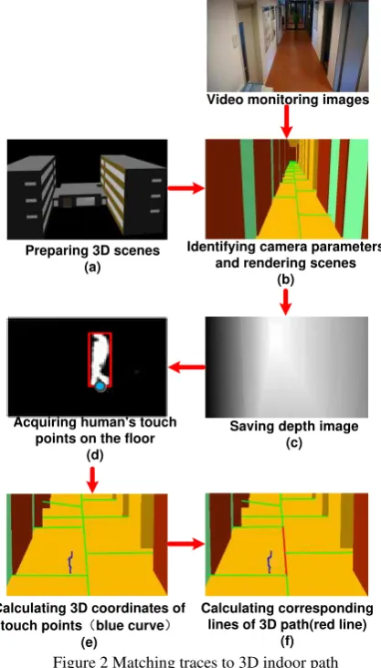
data and obtained depth information of background image in video. We rendered the 3D scenes that had same camera position, pose and visual angle as the original video. Then by taking the center of the bottom of the moving object as a feet position of traced human, we calculated the coordinates of the 3D scenes of the human with depth information and mapping coordinates to the nearest 3D path. Following this procedure we obtained a quite accurate path position.
The key steps of creating depth image can be summarized as follows (Fig.2 (a) - (c)):
1. Prepare 3D scenes: 3D scenes should include what can be seen in video, such like roads, walls, stairs and other main facilities related to path.
2. Identify camera parameters: Camera position, pose, angle of view, aspect ratio, etc.
3. Render the scenes: In OpenGL, we set (visually) the viewpoint to corresponding to the surveillance camera position; we keep line of sight to correspond to the orientation of medial axis of the surveillance camera, and making the view angle to fit the one of the camera, so as to render one frame 3D scene.
4. Save depth image: After rendering, we got depth information of each pixel and saved them.
Preparing 3D scenes (a)
Identifying camera parameters and rendering scenes
(b)
Saving depth image (c) Acquiring human's touch
points on the floor (d)
Calculating 3D coordinates of
touch pointsδblue curveε
(e)
Calculating corresponding lines of 3D path(red line)
(f)
Video monitoring images
Figure 2 Matching traces to 3D indoor path
The steps to create the depth image as listed below (Fig.2 (d) - (f)):
1. Acquire contact points between the human and the floor: When calculating the movement of the human, we took the center point of bottom blob, assuming that this is the human’s feet point.
2. Calculate 3D scenes coordinates related to these touch points: Based on combining pixel coordinates of the touch point with the depth information that was associated with those pixels in the depth image, we calculated 3D coordinates of human’ s projection on the floor. We achieved this via space projection inverse transformation.
3. Calculate the nearest points in 3D path: after comparing minimum distances between the points and edges of the 3D network, we projected 3D scenes coordinates, which corresponding to touch points, to the nearest lines of 3D path. It was taken as the positions of the human in 3D network.
(a) Background
(b) Foreground: green ellipse indicating the person and the red trace of the lowest part of the ellipse
(c) Trace of walking person
Figure 3: Tracking a human
Figure 4 the result of matching video trace to 3D indoor path: the computed trace in red (left) and the matched trace on the 3D
indoor model (in blue)
5. EXPERIMENTS
We have performed several experiments at different buildings. . As discussed above, we detected moving target with Gaussian Mixture Model, using inverse binary thresholding to separate foreground and background. We displayed the feet point (the bottom point of bounding contour of the human) of each frame in the background model, which created continuous trajectory. (Fig. 3). Applying the approach introduced in section four, we matched traces of moving target to the nearest 3D network edge, and those edges became paths of the human in the 3D network.
Figure 5 the result of 3D indoor path tracking. (the purple line denotes the derived path)
If the visible range of multiple surveillance cameras can cover the whole 3D path space and the single moving traces detected by each camera can be matched to the corresponding 3D indoor network, we can get the complete single moving 3D indoor path by simply connecting these 3D paths. If the visible range of multiple surveillance cameras can’t cover the space completely, we might obtain multiple 3D paths. In this case, we need to create the complete path based on the 3D network model. Fig 4 and Fig. 5, show the results. The red line on Fig 4 is the single human traces; the blue line is the virtual path after the matching. The purple line on Fig 5 is the reconstructed path, and we speculate the whole single moving path based on 3D path model.
6. SUMMARY AND FUTURE WORK
This paper presented an approach for single human tracking from surveillance camera and making use 3D network model. The experiments have convincingly shown that the results are stable if the person is walking. As video surveillance systems are widely available in many buildings, we believe this approach have a great potential in indoor security surveillance and indoor navigation. As mentioned above our approach is applicable for only one moving person. In future research we will investigate possibilities to follow multiple moving humans.
ACKNOWLEDGEMENTS
This research is supported by the National Natural Science Foundation of China (No. 41471332, 41101354 and 41571392), the Fundamental Research Funds for the Central Universities (No. ZYGX2015J113), and the National High Technology Research and Development Program of China (No. 2013AA12A302).
REFERENCES
Collins R, Lipton A, Kanade T, Fujiyoshi H, Duggins D, Tsin Y, Tolliver D, Enomoto N, Hasegawa O, Burr P, Wixson L., 2000. A system for video surveillance and monitoring. VSAM final report. Carnegie Mellon University: Technical Report CMU. RI. TR-00-12.
Haritaoglu I, Harwood D, Davis L., 2000. w4: Real-time surveillance of people and their activities. IEEE Transactions on Pattern Analysis and Machine Intelligence, 22(8), pp. 809-830.
Maddalena L, Petrosino A., 2008. A self-organizing approach to background subtraction for visual surveillance applications.
IEEE Transactions on Image Processing, 17(7), pp. 1168-1177.
Magee D., 2004. Tracking multiple vehicles using foreground, background and motion models. Image and Vision Computing, 22(2), pp. 143-155.
Moeslund T B, Granum E., 2001. A survey of computer vision-based human motion capture. Computer Vision and Image Understanding, 81(3), pp. 231-268.
Pai C, Tyan H, Liang Y, Liao H M, Chen S., 2004. Pedestrian detection and tracking at crossroads. Pattern Recognition, 37(5), pp. 1025-1034.
Pavlidis I, Morellas V, Tsiamyrtzis P, Harp S., 2001. Urban surveillance system: From the laboratory to the commercial world. Proceedings of the IEEE, 89(10), pp. 1478-1497.
Persad R., C. Armenakis, G. Sohn., 2012, Integration of video images and CAD wireframes for 3D object localization.
ISPRS Annals of Photogrammetry, Remote Sensing and the Spa
tial Information Sciences, Vol. I-3, 2012 XXII ISPRS
Congress, 25 August-01 September 2012, Melbourne, Australia, pp. 353-358.
Stauffer C, Grimson WEL. Adaptive background mixture models for real-time tracking//Computer Vision and Pattern Recognition, 1999. IEEE Computer Society Conference on. IEEE, 1999, 2.
Tai J, Tsang S, Lin C, Song K., 2004. Real-time image tracking for automatic traffic monitoring and enforcement application.
Image and Vision Computing, 22(6), pp. 485-501.
Zhiqiang Hou, Chongzhao Han., 2006. A Survey of Visual Tracking. ACTA AUTOMATICA SINICA, 32(4), pp. 603-617.