ACCURATE REGISTRATIO
N OF THE CHANG’E
-1 IIM DATA BASED ON LRO
LROC-WAC MOSICA DATA
Z. Yang, Z. Kang*
a Department of Remote Sensing and Geo-Information Engineering, School of Land Science and Technology, China University of Geosciences, Xueyuan Road, Beijing, 100083 CN - (2012160015, zzkang)@ cugb.edu.cn
Commission III, ICWG III/II
KEY WORDS: Chang'E-1, IIM, LROC-WAC, Accurate Registration, Homography Matrix
ABSTRACT:
In the detection of the moon, the visible and near-infrared reflectance data of the lunar material are important information sources for lunar chemical substances and mineral inversion. The Interferometer Imaging Spectrometer (IIM) aboard the Chang'E-1 lunar orbiter is the first multispectral imaging spectrometer for Chinese lunar missions. In this paper, we use the mosaic image of global moon acquired by the Wide-angle Camera (WAC) of the Lunar Reconnaissance Orbiter Camera (LROC) to realize the accurate registration of Chang'E-1 IIM hyperspectral images. Due to the lack of GCPs, the emphasis of this work is to find a huge number of homologous points. The method proposed in this paper is to obtain several homologous points by manually matching, and then we utilize those points to calculate the initial homography matrix of LROC-WAC image and IIM image. This matrix is used to predict the area on IIM image where homologous points may be located, and the locations of the homologous points are determined by the orientation correlation in frequency domain. Finally we save the parts of homologous points which satisfied the conversion relationship of initial homography matrix to calculate homography matrix again. We use this iterative way to obtain a more accurate location of the homologous points. In this process, we take into account that the geometric deformations of different regions on IIM image are quite different. Therefore, we added image threshold segmentation based on the initial homography matrix in the experiment, and completed the above work of finding the homologous points on the segmented images. The final realization of registration accuracy of IIM images are in 1-2 pixels (RMSE). This provides a reliable data assurance for the subsequent study of using IIM images to inverse the lunar elements.
* Corresponding author
1. INTRODUCTION
For the past few decades, image registration has been widely used in many applications including image mosaic (Tsai et al., 2010), deformation detection (Radke et al., 2005), image fusion (Zhang et al., 2011),cartography (Moigne et al., 2012),etc. The purpose of image registration is to obtain two image spatial transform relationships corresponding to the same region, to achieve image to another image transformation. The image registration from different data sources is conducive to data fusion, and then extracts more useful information.
The Wide-angle Camera (WAC) of the Lunar Reconnaissance Orbiter Camera (LROC), almost every month to achieve global moon image coverage (Denevi et al., 2010) , hereinafter referred to as LROC. The Interference Imaging Spectrometer (IIM) is one of the eight payloads of Chang'E-1, responsible for obtaining mineralogical and lunar mineral chemistry information (Ouyang et al., 2010). The reflectance spectral characteristics of lunar surface materials is an important information source for detecting the material properties of the lunar surface and the quantitative inversion of the mineral elements(Lucey, 2006; Zou et al., 2004).The accurate registration of IIM images can provide data for the inversion of global lunar geology mineral elements.
Image registration methods proposed in literatures consist of the following four step like components: feature detection, feature matching, transform model estimation, image resampling and transformation.(Falco et al., 2008). Each of the mentioned
registration steps plays an important role in the registration process. However, among them one of the important steps is the feature matching step(Hossein-Nejad and Nasri, 2016). Feature matching directly affects the results of image registration. At present, the methods of feature matching mainly includes: cross-correlation(Guizar, 2008; Wolberg and Zokai, 2000), FFT-based cross-correlation (Chen et al., 1995; Foroosh et al., 2002; Gilbert, 2002; Reddy and Chatterji, 1996a; Reddy and Chatterji, 1996b),least squares technique (He et al., 2007; Zhao et al., 2016),image matching based on SIFT(Hossein-Nejad and Nasri, 2016; Yi et al., 2008). The least squares method is suitable for cases where the error points are less. SIFT-based feature matching produces more error points, and Wei, Wang et al. proposed the use of RANSAC to eliminate error points(Wei et al., 2008). However, through this way, IIM images have few correct points remain. It is feasible to manually select the homologous points for registration, but a lot of homologous points will cost a huge time and effort. Therefore, the difficulty of IIM and LROC images registration is to find a large number of accurate homologous points on the condition of saving manpower
In this paper, we selected a certain number of homologous points as control points, and try to ensure that these points are evenly distributed on the image. We segmented the IIM and LROC images, and calculated the homography matrix based on the control points from segmented IIM and LROC image blocks. And then, by using the homography matrix, we can predict the position of homologous points. The identity of the homologous
points is by orientation correlation in frequency domain(Fitch et estimation of the registration results is based on more than 200 checking points of each orbits obtained manually. These checking points are not participating in the experiments, which can be used for assessment of the whole image registration results. The RMSE of checking points from different IIM orbits image registration results are in 1-2 pixels.
This paper is divided into four sections. The experimental principle used in this paper is in the second section. The results of the experiment and analysis are in the third section. The conclusion and future work is at the end of this paper.
2. RESEARCH DATA AND METHOD
2.1 Research Data
The IIM images cover about 78% of the lunar region, distributed between 70 ° S and 70 ° N. IIM uses push-sweep imaging, single-orbit imaging width of 25.6km, imaging height of 200km, space resolution of 200m. The IIM images have 32 bands in the range between 480 and 960 nm(Ouyang et al., 2010) . The experimental data used in this paper are 2C level of radiation data which calibrated by the laboratory. As the data of the 1-5, 32 bands SNR are relatively lower, so the experiments exclude these bands(Mingliang et al., 2015; Wu et al., 2012).
The baseline data used in this paper is the mosaic data of the global lunar monochromatic (645nm) image of the Lunar Reconnaissance Orbiter Camera (LROC) Wide Angle Camera (WAC). In order to realize the accurate registration of IIM data, the original IIM images are converted to the moon equirectangular system with LROC image, and the LROC image is resampled to have the same resolution of 200 m/pixel as the IIM images. We also use low-pass filter processing IIM images to smooth image noise. The 25, 20, 11 bands of 26 bands on IIM images are used for RGB color synthesis, which have a better quality. Taking into account the illumination change between IIM images and LROC image is too large. We performed histogram matching of IIM images based on LROC image. Finally, we create the gray-scale image of the IIM images to complete subsequent image matching.
Image registration requires homologous points, the use of traditional cross-correlation method or SIFT method cannot extract a lots of homologous points on the IIM image with high accuracy.Therefore, some homologous points are added as control points in the experiment firstly. These control points can be used to calculate the initial homography matrix, and predict the homologous point’s position.
2.2 Proposed Accurate Registration Method
In this paper, the process of accurate registration is divided into four parts: image segmentation, image matching by orientation correlation(Fitch et al., 2002), fitting the homologous points with quadratic polynomial model (Wong and Fieguth, 2009), image resampling by nearest neighbor resampling and transformation. The main contents of this paper are the image segmentation, image matching and eliminate the mismatch
points. Therefore, in the following description, we mainly explain these parts.
2.2.1 Image Segmentation: IIM images cover large area in the south-north latitude, which requires more homologous points in order to achieve accurate registration of IIM images. Furthermore, the position offsets between the IIM images and the LROC image from different region are different. The whole IIM image cannot be corrected by the simple rotation translation. In this paper, the original IIM and LROC images are divided and calculated the homography matrix(Wang and Liu, 2006) corresponding to the segmented images. Since the homography matrix can define the interrelationship between the two images, any point on an image can find the corresponding point on another image, and the corresponding point is unique(Ueshiba and Tomita, 2003). Using the homography matrix to achieve it’s predicted of the homologous point. Each
The entire image segmentation process can be divided into two steps: image segmentation, image combination. The final realization of the images is unevenly divided. The realization of the method: The IIM and LROC images are divided into small image blocks, and the manually selected control points are also divided into the corresponding image blocks, and then calculate the homography matrix of the current IIM image block and the LROC image block. The current image block is recorded as 1, which indicates the image block has been judged. The equation for the homography matrix is as follows:
[ ′′] = [�� �� �� homogeneous coordinates of the point. The and correspond to the horizontal and vertical coordinates of the LROC image pixel point respectively, and the homogeneous coordinates are expressed as[ ]�. The a1 to a8 correspond to the eight independent pending parameters of the homography matrix, and the image can be corrected at 8 degrees of freedom. So solve the homography matrix at least 4 pairs of homologous points. We use the control point coordinates (greater than 4) of the current images block on LROC to obtain the homography matrix by least squares(Bin et al., 2011). And then create four neighborhood directions of the current image block; four neighborhood directions diagram is as follows:
Figure 1 Four neighborhood direction diagram
Traverses the four neighbourhoods direction of the current image block, if the image block of the current traversal direction
exists and is not marked as 1,and it is judged whether or not the image block can be merged with the current image block A. At the same time, mark the image block of the current traversal direction as 1. The control point coordinates of the current traversing direction LROC image block (e.g., B1) are substituted into the homography matrix, and we can obtained a calculated coordinates � of IIM images block. The actual value �’ has already obtained by manually selected. Thus we can use the offset between the calculated value and actual value. We the current traversal direction and the current traversal direction can be combined. method. At the same time if the calculated value is greater than the threshold in this step, the image block of current traversal direction will not be combined, and determine the next direction of the current image block.
In this process, there may be cases where the number of control points of the image block is less than 4, this time the current image block is merged directly with its traversing direction image block until the number of control points of the combined image block can be used to calculate the homography matrix, and then the image blocks were judged whether can be combined. When the image segmentation is completed, the image blocks of LROC image and IIM images are output along with their corresponding control point coordinates. Subsequent matches are done on those split images.
2.2.2 Image Matching: The illumination of IIM and LROC images vary greatly, after the histogram matching, this difference still exists, reflected in the image is the grayscale difference between homologous points. The traditional image matching methods are mainly based on the grayscale, the grayscale difference between homologous points will lead to a large number of image points match failure or mis-match. Therefore, in this paper ,we use orientation correlation(Fitch et al., 2002). This method is robust to changes in light.
Using the control points’ coordinates on the segmented image blocks, the homography matrix (Equation 1) is calculated by least squares. The coordinates of pixels on the LROC image blocks are substituted into the homography matrix to obtain corresponding predictions of IIM images, and the coordinates of the homologous points can be obtained by using orientation correlation.
Firstly, the IIM and LROC orientation images were constructed: Traversing the pixel points , on the LROC image blocks, creating search window centered on , .and a search window with same size centered on the predicted point , on the IIM image blocks, and the orientation image is created as follows: represents a signal function. The orientation image of the search window on the IIM image is also created according to equation 3, and the value of its pixel on orientation image is denoted as � , .Orientation images are matched using correlation (Gilbert, 2002).Correlation is computed quickly with Fast Fourier Transforms(FFTs).The � , is denoted by � , after fast Fourier transform, and � , corresponds to the value of � , after fast Fourier transform. IFFT () is the inverse transform function of fast Fourier, and �∗ , ) is conjugate to the complex value of � , . The correlation coefficients matrix obtained by the image correlation is calculated as follows:
IFFT( � , ∙ �∗ , )) (4)
By obtaining the maximum value of the correlation coefficients’ matrix, we can get the offset of the homologous point position relative to the center pixel of the IIM search window, and then we can get the coordinate of homologous point.
2.2.3 Error Points Removal: The homologous points obtained by orientation correlation may be exist error points. The method used in this paper to remove the error points is RANSAC(Hartley and Zisserman, 2003). If the image matching can obtain N pairs of the homologous points, the matching point pair �� andP�’ respectively correspond to the points obtained by the LROC image and the points obtained by the orientation correlation on IIM images. The homography matrix is estimated according to the optimal value of the cost function J, as shown in function 5. matrix H which minimizes the above cost function J. According to the equation 6, we determine whether �� is the internal point or the outer point according to the European distance (Equation 6). If �� is the internal point, and then preserve the points pair �� homography matrix obtained by RANSAC only describes four pairs of the homologous points, and its accuracy is difficult to be guaranteed. In addition to the estimation of the homography matrix, the control points we selected should also be included. However, taking into account the control points relative to the homologous points obtained from image matching should have higher accuracy, so we use weighted least
squares method to calculate the homogeneity matrix by the homologous points preserved from RANSAC and the control points.
The homography matrix is used to replace the initial homography matrix to predict the position of the homologous points, and the image matching and error point removal are repeated. At the same time, the manually selected control points on the LROC image block are substituted into the homography matrix to obtain the predicted values on the IIM image block, and calculate the mean offset between all predicted points and their actual values (Equation 2). Iterating this process and found that the mean offset is smaller. When the mean offset tends to be stable, the number of iterations is output and the iterations is stopped .The final positions of the homologous points are output.
3. EXPERIMENTAL RESULT AND ANALYSIS
3.1 Experimental Data
The study data are shown in Figure.2: Fig.A is the LROC image of the global lunar, and b1, b2, b3 represent the IIM image of orbit 2841, 2842, 2843 which be registered in the experiments. The data of the orbit 2843 has a large difference with the data of the orbit 2841, 2842 in the coverage of the north and south latitudes (coverage smaller), so the data is considered separately in the subsequent image segmentation.
3.2 Result of Accurate Registration
The contents of the experiment include the image segmentation, the image matching, and the removal of the mismatch points. Through the above experiments we can obtain a large number of homologous points from IIM images of orbits 2841, 2842, 2843, respectively. The quadratic polynomial of LROC image and IIM image is fitted with these homologous points, and the polynomial is used to realize the accurate registration of IIM image data by image nearest neighbor resampling.
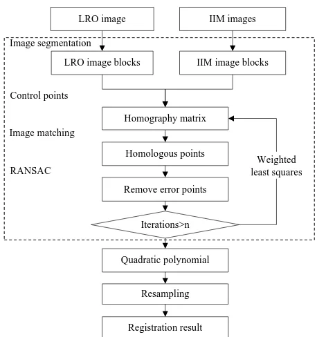
In this paper, the accurate registration flow chart is as follows, in which part of the dashed box is the main experimental contents of this paper:
3.2.1 Image Segmentation: Image segmentation can be divided into image segmentation and image combination. Different sizes of image blocks can be obtained after the image segmention. We should try to ensure that the small image block before combining should contain at least four manually selected control points, so as to be used to calculate the homography matrix to determine the combine threshold (Equation 2). This point we have already mentioned in the section 2.2.1. In addition, IIM images on both sides (Fig.6 b1, b2, b3) have no data, in the experiment the corresponding range of IIM images and LROC image should not be added into the image segmentation. Finally, different size of image blocks both on LROC image and IIM images were obtained(Orbit 2841,2842, 2843).
Figure 2. LROC image (A) and three orbiter images of IIM: image 2841(b1), image 2842 (b2), image 2843 (b3)
Figure 3. The accurate registration flow chart
LRO image IIM images
LRO image blocks IIM image blocks
Homologous points
Quadratic polynomial
Registration result Resampling Image segmentation
Image matching
Homography matrix
Remove error points RANSAC
Control points
Iterations>n
Weighted least squares The International Archives of the Photogrammetry, Remote Sensing and Spatial Information Sciences, Volume XLII-3/W1, 2017
The following table shows the number of control points manually selected on the three orbits of IIM in this paper, the number of cutting times in the image x and y directions, and the number of image blocks corresponding to each orbital images acquired after image segmentation. It can be seen from the table that the number of cutting images is related to the number of manually selected control points. As the IIM orbital image 2843 is not complete, it has a different number of split. Its number of pixels in the x, y direction is less than orbital images of 2841,
Table 1. IIM images of each orbital data segmentation
3.2.2 Orientation Correlation and Error Points Removal: After image segmentation we get the image blocks of the IIM images for each orbit. In the image matching process, each orbit image of the IIM to traverse all the image blocks on them, to complete the image matching and get homologous points of whole orbit. So the image matching is actually completed on the different size of image blocks. In the image matching, we calculate the initial homography matrix (Equation 1) based on the coordinates of the control points corresponding to the image blocks. Since only the control points are calculated, the weights of all control points is set to 1.And then traverse the points on centered on the point on the LROC image block to complete the orientation correlation (2.2.2). The match is completed in the frequency domain, the matching time of the method is short and the image matching can be done in a few minutes. We use RANSAC to remove the mismatch points (2.2.3) of the image, and use the remained “internal points” combining with manual selected control points to update the homography matrix by weighted least squares method.
Due to the high precision of the manually selected control points, and the number of control points is relatively small; we give the control points weighted value of 1 after several tests. However, the method proposed in this paper to obtain a large number of the homologous points as the weight of 0.1. The updated homography matrix can be used to calculate the predicted coordinates of the homologous points and to complete the image matching. All the image blocks after four iterations the mean offset of manually selected control points between predict value and actual value tend to be stable (Equation 2), and finally output the homologous points.
Each orbit of the image data we have carried out four groups of experiments to test a different number of manually selected control points through the method proposed in this paper to get
a huge number of homologous points. The final number of homologous points and the matching time as follows:
Table 2. The number of homologous points and matching time
3.3 Results Analysis
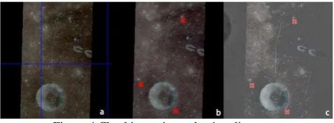
In this paper, we use a number of homologous points added manually on the image to evaluate the registration results of our proposed method. Those homologous points can be viewed as checking points. Checking points selection method: creating grid in the LROC and IIM original image (Fig.4 a), manually select the checking points on the image added grid. The purpose of this step is to ensure that the checking points are evenly distributed on the image. These points are not included in the experiments in this paper and can be used as an assessment of the entire IIM image registration result. After the experiments in the text we can automatically get a large number of the homologous points, those points were used to fit the quadratic polynomial model to achieve the registration of the IIM images added checking points (Fig.4 b) The ideal result of the registration is that the IIM images after registration can be completely coincident with the LROC image, and the positions of the checking points are coincident (Fig.4 c).
Figure 4 Checking points selection diagram
If the checking point’s location of IIM registration image and LROC image exist deviation .This can be considered as the error of registration results. Based on this criterion, we evaluated the registration results using the offsets between the checking points on the corrected IIM image and the checking point coordinates of the corresponding position on the LROC image, where the orbit 2841 selected 366 checking points, orbit 2842 selected 363 checking points, orbit 2843 selected 284 checking points.
The following table shows the root mean square error (RMSE) of the checking points’ offset, the number of homologous points obtained from the above experiments and the number of manually selected control points. From this table we can draw the conclusion that the method proposed in this paper can extract a huge number of homologous points, and the RMSE of all experiments are within two pixels, of which the bold displays are the best results of three orbital image registrations.
Orbits Homologouspoints Matching time s
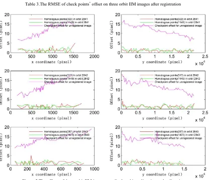
Fig.5 shows the checking points’ offsets from each orbit of the IIM image displayed in the x-direction and y-direction of the image. The pink line corresponds to the checking points’ offsets between the origin IIM images and LRO image, the green line corresponds to the checking points’ offsets by method proposed in this paper, while the red line corresponds to the checking points’ offsets of manually selected homologous points. It can be seen the method proposed in this paper can realize the accurate registration of IIM images .Compared the checking
points’ offsets of registration method by manually selected homologous points and registration method proposed in this paper, it can be seen that the maximum offsets of the registration method by manually selected homologous points is reduced through the registration method proposed in this paper. Where the 2841 orbital offset in x direction is reduced from five pixels to three pixels, the maximum offset of the orbit 2842 in the x direction is also reduced from three pixels to two pixels, and the maximum value of the offset in y direction of orbit 2842 Orbits RMSE/Number of homologous points/Number of control pointsExperiment1 Experiment2 Experiment3 Experiment4
2841 1.440/1907/60 1.423/1778/80 1.323/1149/108 1.378/1135/156
2842 1.488/788/60 1.424/1449/80 1.500/1869/108 1.575/1416/156
2843 1.553/828/53 1.509/1335/66 1.474/1077/85 1.385/1423/107
Table 3.The RMSE of check points’ offset on three orbit IIM images after registration
Figure 5.The offsets of three orbit IIM images are displayed in x direction and y direction
Figure 6.The results of comparison before and after registration
is reduced from four pixels to two pixels, the maximum offset in the orbit 2843 x direction is reduced from five pixels to two pixels. The offsets of all points are within 3 pixels.
The positions of the larger checking point’s offsets before image registration are mainly concentrated on the upper panel and the right panel of the image. The difference between the entire IIM images offsets can reach more than a dozen pixels. After image registration, the checking points’ offsets of the IIM and LRO images no longer reflect this trend. The checking points’ offsets between the registration images and LRO image are all reduced to a smaller value.
Finally, we marked the checking point’s offsets in size and direction on the mosaic image of three orbital images. Fig.6 in the left picture shows results that the original three orbits of the IIM images superimposed on the LROC image, Fig.6 on the right is the mosaic of the IIM registration images superimposed on the LROC image, and the arrow indicates the direction of the offset. We circled the lunar craters in red. There existed a large deviation between the IIM images and the LROC image before the IIM images are registered, and the positions of lunar craters coincide after registration. The sizes of these offsets marked on the map are basically within 2 pixels.
4. CONCLUSIONS AND FUTURE WORKS
IIM images have a large coverage in the north-south latitude. Therefore, the registration method in this paper focuses on how to obtain a huge number of accurate homologous points to the orientation correlation to obtain the homologous point coordinates to achieve image registration. The experiment results show that the proposed method in this paper can obtain a huge number of accurate coordinates of the homologous points. The RMSE of checking points of best registration results on three orbital IIM images are all within 1.5 pixels. The method propose in this paper can achieve the accurate registration of the image. Subsequent studies will focus on how to further reduce the manual selection of control points to obtain more accurate results.
REFERENCES
Bin, W.U., Zhu, H.Y., Xiao, X.T., Xue, T., 2011. Extraction of plane target image features based on homography matrix in visual measurement. Journal of Optoelectronics Laser 22, 1211-1215.
Chen, Q., Defrise, M., Deconinck, F., 1995. Symmetric Phase-Only Matched Filtering of Fourier-Mellin Transforms for Image Registration and Recognition. Pattern Analysis & Machine Intelligence IEEE Transactions on 16, 1156-1168.
Denevi, B.W., Robinson, M.S., Sato, H., Hapke, B.W., Eliason, E.M., Hiesinger, H., Jolliff, B.L., Malin, M.C., Mcewin, A.S., Ravine, M.A., 2010. Lunar Reconnaissance Orbiter Wide Angle Camera Observations of the Moon, European Planetary Science Congress 2010, p. 333".
Falco, I.D., Cioppa, A.D., Maisto, D., Tarantino, E., 2008. Differential Evolution as a viable tool for satellite image registration. Applied Soft Computing 8, 1453-1462.
Fitch, A.J., Kadyrov, A., Christmas, W.J., Kittler, J., 2002. Orientation Correlation, British Machine Vision Conference 2002, BMVC 2002, Cardiff, Uk, 2-5 September, pp. 133--142.
Foroosh, H., Zerubia, J.B., Berthod, M., 2002. Extension of phase correlation to subpixel registration. IEEE Transactions on Image Processing A P ublication of the IEEE Signal Processing Society 11, 188-200.
Gilbert, R., 2002. Evaluation of FFT Based Cross-Correlation Algorithms for Ppaper Image Velocimetry. University of Waterloo. Least Square Technique for Simultaneous Image Registration and Super-Resolution. IEEE Transactions on Image Processing 16, 2830-2841.
Hossein-Nejad, Z., Nasri, M., 2016. An adaptive image registration method based on SIFT features and RANSAC transform ☆. Computers & Electrical Engineering.
Lucey, P.G., 2006. Understanding the Lunar Surface and Space-Moon Interactions. Reviews in Mineralogy & Geochemistry 60, 83-219.
Mingliang, M.A., Wang, C., Shi, R., Gao, W., 2015. The Research and Assessment of Topographic Registration and Correction of Chang'E-1 IIM Data Based on LRO LOLA DEM Data. Journal of Geo-Information Science.
Ouyang, Z.Y., Chunlai, L.I., Zou, Y.L., Zhang, H.B., Chang, L., Liu, J.Z., Liu, J.J., Wei, Z., Yan, S.U., Wen, W.B., 2010. Primary scientific results of Chang'E-1 lunar mission. Science China Earth Sciences 53, 1565-1581.
Radke, R.J., Andra, S., Al-Kofahi, O., Roysam, B., 2005. Image change detection algorithms: a systematic survey. IEEE Transactions on Image Processing A Publication of the IEEE Signal Processing Society 14, 294.
Reddy, B.S., Chatterji, B.N., 1996a. An FFT-based technique for translation, rotation, and scale-invariant image registration. IEEE Transactions on Image Processing A Publication of the IEEE Signal Processing Society 5, 1266-1271.
Tsai, C.L., Li, C.Y., Yang, G., Lin, K.S., 2010. The edge-driven dual-bootstrap iterative closest point algorithm for registration of multimodal fluorescein angiogram sequence. IEEE Transactions on Medical Imaging 29, 636-649.
Ueshiba, T., Tomita, F., 2003. Plane-based calibration algorithm for multi-camera systems via factorization of homography matrices, IEEE International Conference on Computer Vision, 2003. Proceedings, pp. 966-973 vol.962.
Wang, J., Liu, Y., 2006. Characteristic Line of Planar Homography Matrix and Its Applications in Camera Calibration, International Conference on Pattern Recognition, pp. 147-150.
Wei, W., Hong, J., Tang, Y., 2008. Image Matching for Geomorphic Measurement Based on SIFT and RANSAC Methods, International Conference on Computer Science and Software Engineering, pp. 317-320.
Wolberg, G., Zokai, S., 2000. Image registration for perspective deformation recovery, Aerosense, p. 12.
Wong, A., Fieguth, P., 2009. Fast phase-based registration of multimodal image data. Signal Processing 89, 724-737.
Wu, Y., Zhang, X., Yan, B., Gan, F., Tang, Z., Xu, A., Zheng, Y., Zou, Y., 2012. Global absorption center map of the mafic minerals on the Moon as viewed by CE-1 IIM data. Science China 55, 561-562.
Yi, Z., Zhiguo, C., Yang, X., 2008. Multi-spectral remote image registration based on SIFT. Electronics Letters 44, 107-108.
Zhang, Q., Wang, L., Li, H., Ma, Z., 2011. Similarity-based multimodality image fusion with shiftable complex directional pyramid. Pattern Recognition Letters 32, 1544-1553.
Zhao, W., Tian, Z., Yang, L., Yan, W., Wen, J., 2016. Image registration using a kernel partial least squares based mismatches removal method. AEU - International Journal of Electronics and Communications 70, 427-435.
Zou, Y.L., Liu, J.Z., Liu, J.J., Xu, T., 2004. Reflectance Spectral Characteristics of Lunar Surface Materials. Research in Astronomy and Astrophysics 4, 97-104.