for Real-World Haptics
September 2014
A thesis submitted in partial fulfillment of the requirements for the degree of
Doctor of Philosophy in Engineering
Keio University
Graduate School of Science and Technology
School of Integrated Design Engineering
This dissertation is the summary of my research from April 2009 to September 2014 as the member of Katsura laboratory in Keio University. Five years and a half have passed since I entered the Katsura laboratory, the Faculty of Science and Technology, Keio University. With full of kind people and under good environments, I was able to focus on my research work. Moreover, I was able to obtain valuable experiences. Without the helps from people and environments, I did not think I could manage the research activities.
First of all, I would like to express my appreciation to my supervisor Associate Professor Dr. Seiichiro Katsura in Keio University. His insightful teaching and comments always supported and kept motivating my research work. I greatly feel grateful to the members of my Ph. D. dissertation committee, Professor Dr. Kouhei Ohnishi in Keio University, Professor Dr. Hideo Saito in Keio University, and Associate Professor Dr. Yoshihiro Taguchi in Keio University.
I would like to show my gratitude to the Professors who gave precious comments at the research meetings. I sincerely would like to express my appreciation to Professor Dr. Kouhei Ohnishi in Keio University, Professor Dr. Toshiyuki Murakami in Keio University, Professor Dr. Hiroaki Nishi in Keio University, Associate Professor Dr. Takahiro Yakoh in Keio University, and Associate Professor Dr. Seiichiro Katsura in Keio University.
During my course, I had the experience to study in University of California, Berkeley. I would like to show my gratitude to the “International Collaborative Research of Perception and Expression Media for Development of Medical Access Space,” the one of the programs of “Strategic Young Researcher Overseas Visits Program for Accelerating Brain Circulation,” for providing me the great opportunity. I feel grateful to Professor Dr. Masayoshi Tomizuka in University of California, Berkeley. He supported my life in California and gave valuable comments to my research.
As my career of research activities, the Japan Society for the Promotion of Science (JSPS) has pro-vided me the financial support. I would like to show my gratitude to the organization. I feel grateful for the Global COE Program “High-Level Global Cooperation for Leading-Edge Platform on Access Space (C12)” for financially helping me. In addition, I would like to show my appreciation to Strategic Information and Communications R&D Promotion Programme (SCOPE) and Ministry of Education,
I would like to express my gratitude to my family for supporting me. Their dedicate assistance really helped my life.
Lastly, I would like to express my appreciation again for all people who supported my research activ-ities.
September, 2014 Hidetaka Morimitsu
Acknowledgements i
Table of Contents ii
List of Figures vi
List of Tables xi
1 Introduction 1
1.1 Background of This Dissertation . . . . 1
1.1.1 Recognition of Remote Environment via Transmission of Audiovisual Information 1 1.1.2 Real-world Haptics for Kinesthetic Sensation and Motion Control. . . . 2
1.1.3 Technologies on Thermal Haptics . . . . 5
1.2 Motivation of This Dissertation . . . . 7
1.3 Chapter Organization of This Paper . . . . 9
2 Robust Control of Across Variable Flow 12 2.1 Introduction . . . . 12
2.2 Generalized Physical Variables. . . . 13
2.2.1 Analogies Between Different Kinds of Physical Systems . . . . 13
2.2.2 Across and Through Variables . . . . 17
2.3 Generalized Form of Control Device . . . . 18
2.4 Robust Control of Across Variable Flow . . . . 20
2.5 Case of Thermodynamic Systems . . . . 22
2.6 Generalized Control Conductance and Control Systems . . . . 23
2.6.1 Generalized Control Conductance . . . . 23
2.6.2 Control System of Across Variable. . . . 24
2.6.3 Control System of Through Variable . . . . 25
2.8.2 Results of Experiments (Across Variable Control) . . . . 29
2.9 Experiments on Through Variable Control . . . . 32
2.9.1 Overview of Experiments (Through Variable Control) . . . . 32
2.9.2 Results of Experiments (Through Variable Control) . . . . 33
2.10 Summary of Chapter 2 . . . . 35
3 Bilateral Control Based on Across Variable Flow for Reproduction of Physical Power In-teraction 36 3.1 Introduction . . . . 36
3.2 Reproduction of Generalized Power Interaction . . . . 37
3.3 Generalized Reproduction of Bilateral Power Flow . . . . 38
3.3.1 AVF-based 4ch Control System . . . . 38
3.3.2 Comparative Methods . . . . 39
3.4 Analyses Based on Generalized Intermediate Impedance. . . . 40
3.4.1 Hybrid Parameters of Control Systems. . . . 40
3.4.2 Symmetric Property and Hybrid Parameters . . . . 41
3.4.3 Generalized Intermediate Impedance. . . . 43
3.5 Analyses Based on Bond Graphs . . . . 47
3.5.1 Lyapunov-based Analyses Using Bond Graph . . . . 47
3.5.2 Bond Graph of AVF-based 4ch Bilateral Control. . . . 47
3.5.3 Bond Graph of Reflection-based Bilateral Control . . . . 49
3.6 Analyses Based on Pole Placements . . . . 51
3.7 Common-Mode Control of Entropy Flows . . . . 53
3.8 Experiments of Bilateral Control . . . . 54
3.8.1 Overview of Experiments (Bilateral Control) . . . . 54
3.8.2 Results of Experiments (Bilateral Control) . . . . 56
3.8.3 Results of Experiments (Generalized Intermediate Impedances) . . . . 59
3.8.4 Results of Experiments (Comparison with Reflection-based Control) . . . . 64
3.9 Summary of Chapter 3 . . . . 66
4 Performance Enhancement of Bilateral Control under Communication Delay 67 4.1 Introduction . . . . 67
4.2 Bilateral Control under Time Delay . . . . 68
4.4 Design of Through Variable Compensator . . . . 74
4.4.1 Through Variable Compensator for Sub-optimal Tracking . . . . 74
4.4.2 Modification of Through Variable Compensator . . . . 75
4.4.3 Determination of Gaink . . . . 79
4.5 Simulations of Using Phase-lag Compensator . . . . 79
4.6 Experiments of Using Compensator for Through Variable Control . . . . 82
4.6.1 Overview of Experiments (Compensator for Through Variable Control) . . . . . 82
4.6.2 Results of Experiments (Compensator for Through Variable Control) . . . . 84
4.7 Experiments of Comparison Using Hybrid Parameters . . . . 86
4.7.1 Overview of Experiments (Comparison Using Hybrid Parameters) . . . . 86
4.7.2 Results of Experiments (Comparison Using Hybrid Parameters) . . . . 88
4.8 Summary of Chapter 4 . . . . 91
5 Bilateral Control Between Systems with Different Control Performances 92 5.1 Introduction . . . . 92
5.2 Bilateral Control Between Different Control Performances . . . . 94
5.3 Analyses on Modal Space of Bilateral Control Between Different Bandwidths. . . . 96
5.4 Construction of Compensator for Interference Terms. . . . 97
5.5 Discussions on the Effectiveness of Using the Compensator . . . . 100
5.6 Experiments of Bilateral Control with Different Bandwidths . . . . 101
5.6.1 Overview of Experiments (Bilateral Control with Different Bandwidths) . . . . 101
5.6.2 Results of Experiments (Bilateral Control with Different Bandwidths). . . . 103
5.7 Summary of Chapter 5 . . . . 105
6 Bandwidth Improvement of Thermal Haptic Display for Mixed Rendering of Mechanical and Thermal Sensations 106 6.1 Introduction . . . . 106
6.2 Modeling of Thermoelectric Device . . . . 107
6.2.1 Structure and Coordinates of Thermoelectric Device. . . . 107
6.2.2 Transfer Functions of Electrode and Ceramic Plate Part . . . . 109
6.2.3 Block Diagram of Peltier Device. . . . 110
6.3 Heat Inflow Observer. . . . 111
6.3.1 Construction of Heat Inflow Observer . . . . 111
6.6 Experiments of Observer-based Heat Inflow Estimation . . . . 116
6.6.1 Overview of Experiments (Heat Inflow Estimation) . . . . 117
6.6.2 Results of Experiments (Output Modification of Heat Flow Sensor) . . . . 119
6.6.3 Results of Experiments (Estimation of Heat Inflow) . . . . 120
6.6.4 Results of Experiments (Observer-based Control of Heat Inflow) . . . . 121
6.7 Experiments of Observer-based Thermal Bilateral Control . . . . 122
6.7.1 Overview of Experiments (Observer-based Thermal Bilateral Control) . . . . . 122
6.7.2 Results of Experiments (Observer-based Thermal Bilateral Control). . . . 123
6.8 Experiments of Mixed Rendering of Mechanical and Thermal Sensations . . . . 124
6.8.1 Overview of Experiments (Mixed Rendering of Mechanical and Thermal Sensa-tions). . . . 124
6.8.2 Results of Experiments (Mixed Rendering of Mechanical and Thermal Sensations)125 6.9 Summary of Chapter 6 . . . . 127
7 Conclusions 128
References 134
1-1 Transmission flow of audiovisual information. . . . . 2
1-2 Kinesthetic bilateral control. . . . . 3
1-3 Thermal interaction between operator and device. . . . . 5
1-4 The motivation of this dissertation. . . . . 8
1-5 Chapter organization of this dissertation. . . . . 10
2-1 Distributed parameter model of each physical system. (a) Mechanical system (wave equation). (b) Electrical system (telegraphic equation). (c) Thermal system (thermal diffusion equation).. . . . 13
2-2 Elements in each physical system based on mobility analogy. . . . . 17
2-3 Generalized control device described by using bond graph. . . . . 18
2-4 Generalized control device described by using block diagram. . . . . 19
2-5 Robust control of AVF based on observer of disturbance through variable.. . . . 20
2-6 Bond graph of robust control of AVF. . . . . 21
2-7 Approximated bond diagram of perfect AVF control. . . . . 21
2-8 Estimation of disturbance heat flow. . . . . 23
2-9 Bond graph of across variable control. . . . . 25
2-10 Bond graph of through variable control. . . . . 25
2-11 Examples of multi-degree-of-freedom system. . . . . 26
2-12 Experimental setup of across variable control (mechanical system). . . . . 28
2-13 Experimental setup of across variable control (thermal system). . . . . 28
2-14 Experimental results of across variable control (mechanical system). . . . . 30
2-15 Experimental results of across variable control (thermal system). . . . . 30
2-16 Experimental results of across variable control (mechanical system and without distur-bance observer). . . . . 31
2-17 Experimental results of across variable control (thermal system and without disturbance observer). . . . . 31
2-21 Experimental results of through variable control (thermal system).. . . . 33
3-1 Schematic of bilateral control for reproduction of power interaction. . . . . 37
3-2 Block diagram of the AVF-based 4ch control system. . . . . 39
3-3 Generalized intermediate impedance in power transmission. . . . . 43
3-4 Impedances in the case of across variable-based bilateral control. . . . . 45
3-5 Impedances in the case of through variable-based bilateral control. . . . . 45
3-6 Impedances in the case of AVF-based bilateral control (Ceis changed). . . . . 46
3-7 Impedances in the case of AVF-based bilateral control (Ciis changed). . . . . 46
3-8 Bond graph of AVF-based 4ch control. . . . . 48
3-9 Approximated bond graph for stability analysis of AVF-based 4ch control. . . . . 48
3-10 Bond graph of reflection-based control. . . . . 50
3-11 Approximated bond graph for stability analysis of reflection-based control. . . . . 50
3-12 Pole movements of AVF-based 4ch control system. . . . . 52
3-13 Pole movements of reflection-based control system. . . . . 52
3-14 Entropy flow in thermal bilateral control.. . . . 53
3-15 Experimental setup of bilateral control (mechanical system).. . . . 54
3-16 Experimental setup of bilateral control (thermal system). . . . . 54
3-17 External environments used for thermal bilateral control. . . . . 54
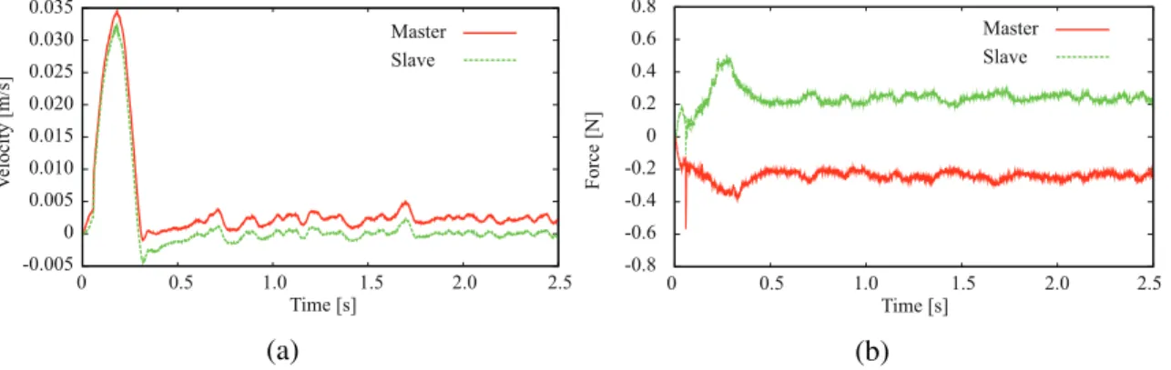
3-18 Experimental results of across variable-based bilateral control (mechanical system). (a) Velocity responses. (b) Force responses. . . . . 56
3-19 Experimental results of through variable-based bilateral control (mechanical system). (a) Velocity responses. (b) Force responses. . . . . 56
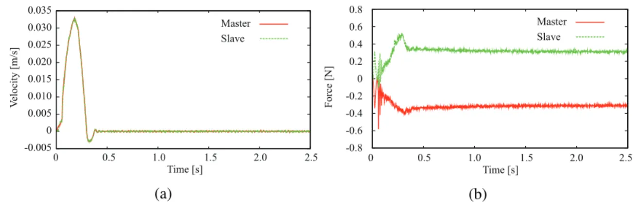
3-20 Experimental results of AVF-based 4ch bilateral control (mechanical system). (a) Veloc-ity responses. (b) Force responses. . . . . 57
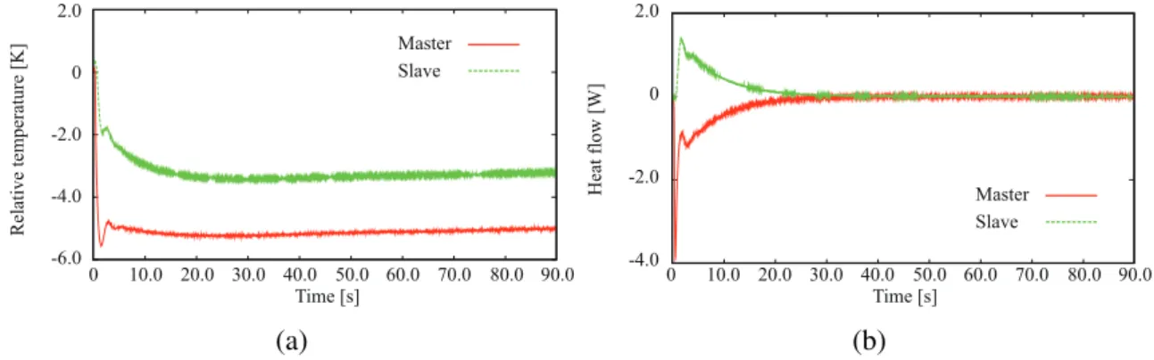
3-21 Comparison of velocity and force responses. (a) Velocity responses. (b) Force responses. 57 3-22 Experimental results of across variable-based bilateral control (thermal system). (a) Tem-perature responses. (b) Heat flow responses. . . . . 58
3-23 Experimental results of through variable-based bilateral control (thermal system). (a) Temperature responses. (b) Heat flow responses. . . . . 58
3-24 Experimental results of AVF-based 4ch bilateral control (thermal system). (a) Tempera-ture responses. (b) Heat flow responses. . . . . 59
3-25 Comparison of temperature responses. . . . . 59
3-29 Intermediate impedance of AVF-based bilateral control (mechanical case,Ciis changed). 61
3-30 Intermediate impedance of across variable-based bilateral control (thermal case). . . . . 62
3-31 Intermediate impedance of through variable-based bilateral control (thermal case). . . . 62
3-32 Intermediate impedance of AVF-based bilateral control (thermal case,Ceis changed). . 63
3-33 Intermediate impedance of AVF-based bilateral control (thermal case,Ciis changed).. . 63
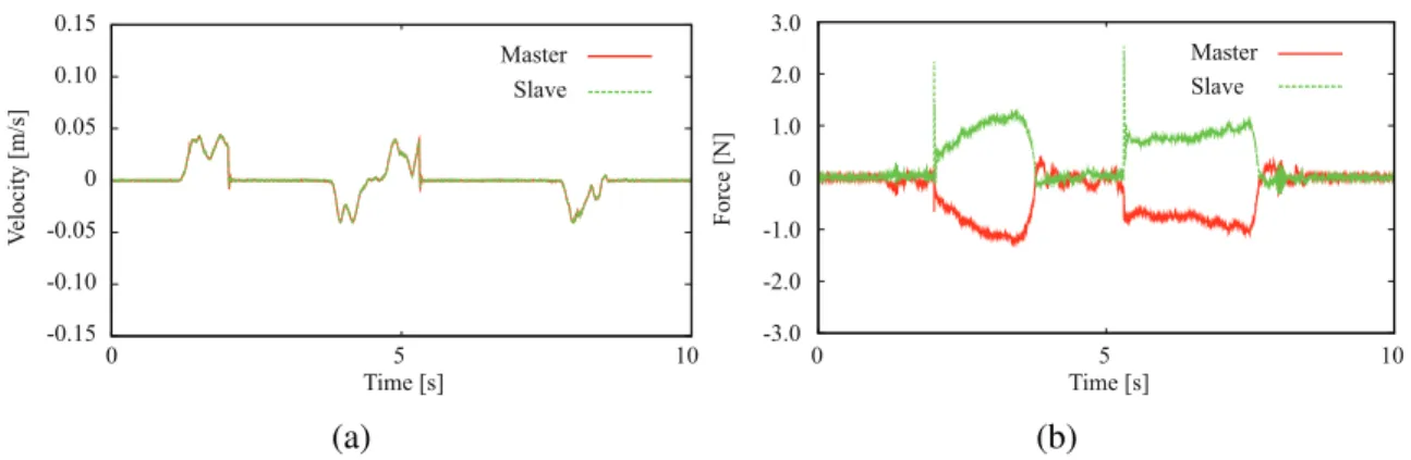
3-34 Experimental results of AVF-based bilateral control (mechanical system, contact with aluminum block). (a) Velocity responses. (b) Force responses. . . . . 64
3-35 Experimental results of reflection-based bilateral control (mechanical system, contact with aluminum block). (a) Velocity responses. (b) Force responses. . . . . 64
3-36 Experimental results of AVF-based bilateral control (thermal system, contact with cooled aluminum block). (a) Temperature responses. (b) Heat flow responses. . . . . 65
3-37 Experimental results of reflection-based bilateral control (thermal system, contact with cooled aluminum block). (a) Temperature responses. (b) Heat flow responses. . . . . 65
4-1 AVF-based 4ch bilateral control under time delay. . . . . 69
4-2 Bilateral control with phase-lag compensator under time delay. . . . . 70
4-3 Block diagram of differential modal space under time delay. . . . . 72
4-4 Gain diagram of1 +e−T sCcp. . . . . 73
4-5 Gain diagram ofCcpi(the case ofCe= 30.0,T = 0.1,Ccpe = (0.5s+ 10.0)/(s+ 10.0)). 75 4-6 Gain diagram of Ccpi (The case ofCe = 30.0, Ci = 1.0, T = 0.1, Ccpe = (0.5s+ 10.0)/(s+ 10.0)). . . . . 76
4-7 Idea of modifying the compensatorCcpi. . . . . 76
4-8 Implementation ofCcpi. . . . . 77
4-9 Gain diagrams of hybrid parameters with different gaink(changed from0.0with incre-ment of0.2). . . . . 78
4-10 Simulation results of bilateral control without phase-lag compensation (free operation). (a) Position responses. (b) Force responses. . . . . 80
4-11 Simulation results of bilateral control with phase-lag compensation (free operation). (a) Position responses. (b) Force responses. . . . . 80
4-12 Simulation results of bilateral control without phase-lag compensation (contact motion). (a) Position responses. (b) Force responses. . . . . 81
4-13 Simulation results of bilateral control with phase-lag compensation (contact motion). (a) Position responses. (b) Force responses. . . . . 81
Position responses in X direction. (b) Position responses in Y direction. (c) Force
responses inXdirection. (d) Force responses inY direction. . . . . 84
4-17 Experimental results of bilateral control under time delay (with compensator). (a) Posi-tion responses inXdirection. (b) Position responses inY direction. (c) Force responses inXdirection. (d) Force responses inY direction. . . . . 85
4-18 Values of compensator gaink. (a)kfor control in Xdirection. (b) kfor control inY direction. . . . . 86
4-19 Experimental setup used for comparing with other compensation methods. . . . . 87
4-20 Experimental results of measuring hybrid parameters. (a) Results of measuringH12and H12′ . (b) Results of measuringH21andH21′ . . . . . 89
4-21 Experimental results of measuring symmetric ratios. (a) Symmetric ratioR12. (b) Sym-metric ratioR21. . . . . 90
5-1 AVF control of haptic device that has imperfect transmission characteristics. . . . . 93
5-2 Equivalent block diagram of the AVF control. . . . . 94
5-3 AVF-based 4ch bilateral control with different control performances. . . . . 95
5-4 Differential modal space of the bilateral control. . . . . 96
5-5 Common modal space of the bilateral control. . . . . 97
5-6 Disturbance observer constructed in common modal space. . . . . 98
5-7 Compensation for the disturbance in common modal space. . . . . 99
5-8 Equivalent block diagram of common modal space. . . . . 100
5-9 Experimental setup of bilateral control (different bandwidths, mechanical system). . . . 101
5-10 Experimental setup of bilateral control (different bandwidths, thermal system). . . . . . 101
5-11 Experimental results of system with different control performances (mechanical control, without compensation). (a) Velocity responses. (b) Force responses. . . . . 103
5-12 Experimental results of system with different control performances (mechanical control, proposed system). (a) Velocity responses. (b) Force responses. . . . . 103
5-13 Experimental results of system with different control performances (thermal control, without compensation). (a) Temperature responses. (b) Heat flow responses. . . . . 104
5-14 Experimental results of system with different control performances (thermal control, pro-posed system). (a) Temperature responses. (b) Heat flow responses. . . . . 104
6-3 Block diagram of heat transfer in Peltier device. . . . . 111
6-4 Block diagram of the heat inflow observer. . . . . 112
6-5 Approximated block diagram of Peltier device. . . . . 113
6-6 Heat inflow observer based on approximated model. . . . . 113
6-7 Coordinate of thermal sensor. . . . . 114
6-8 Block diagram for identifying thermal contact resistance. . . . . 116
6-9 Experimental setup for heat inflow estimation. . . . . 117
6-10 Schematic representation of experimental setup (estimation of heat inflow). . . . . 117
6-11 Schematic representation of experimental setup (modification of output of heat flow sen-sor). . . . . 118
6-12 Experimental results (0.1 Hz). (a) Temperature responses. (b) Heat flow responses. . . . 119
6-13 Heat flow responses (contact). . . . . 120
6-14 Estimation results of heat inflow. . . . . 120
6-15 Results of heat inflow control (reference:1.0 W). . . . . 121
6-16 Experimental setup for observer-based thermal bilateral control. . . . . 122
6-17 Experimental results of thermal bilateral control (use of heat inflow observer). (a) Tem-perature responses (the case without using the observer). (b) Heat inflow responses (the case without using the observer). (c) Temperature responses (the case with using the observer). (d) Heat inflow observer (the case with using the observer).. . . . 123
6-18 Experimental setup for mixed rendering of mechanical and thermal sensations. . . . . . 124
6-19 Operation example of the mixed rendering system of mechanical and thermal sensations. 125 6-20 Experimental results of mixed rendering of mechanical and thermal sensations. (a) Re-sponses of across variables (with the heat flow sensor). (b) ReRe-sponses of across variables (with the observer). (c) Responses of through variables (with the heat flow sensor). (d) Responses of through variables (with the observer). . . . . 126
2.1 Across and through variables based on mobility analogy. . . . . 17
2.2 Parameter values for experiments (mechanical system). . . . . 29
2.3 Parameter values for experiments (thermal system). . . . . 29
3.1 Control objectives for each physical system. . . . . 38
3.2 Parameter values for plotting gain diagrams. . . . . 44
3.3 Parameter values for plotting pole movements. . . . . 51
3.4 Parameter values for bilateral control (mechanical system). . . . . 55
3.5 Parameter values for bilateral control (thermal system). . . . . 55
4.1 Parameter values used for simulations. . . . . 79
4.2 Parameter values used for experiments of controlling 2-link manipulators. . . . . 83
4.3 Parameter values used for comparative methods. . . . . 87
5.1 Parameter values for bilateral control with different control performances (mechanical system). . . . . 102
5.2 Parameter values for bilateral control with different control performances (thermal system).102 6.1 Parameter values used for identification. . . . . 118
6.2 Measured gains from electrical current to surface temperature.. . . . 121
6.3 Parameter values for bilateral control (observer-based thermal bilateral control).. . . . . 122
6.4 Parameter values for bilateral control (mixed rendering of mechanical and thermal sen-sations). . . . . 125
Introduction
In Chapter 1, the background, motivation and chapter organization of this dissertation are described. For explaining the former two parts, the related studies are introduced.
1.1
Background of This Dissertation
1.1.1 Recognition of Remote Environment via Transmission of Audiovisual Information Recognition of environment is important and essential factor for human beings. The obtainment of physical information on things and external environment is enabled by the functions of sensory organs. Based on the information, humans decide their actions and live in this world.
One of the challenging themes in engineering has been the extension of the recognition functions so that those work beyond the spatial constraints. In old days, humans had no means to sense the information on remote environment. The only ways they could utilize were letter and hearing from other people and to deduce the state of remote environment by making full use of such text and linguistic information. The telephone invented by Alexander Graham Bell was a innovation in a sense that humans obtained the mean to hear the sound at remote place. This function is brought by transforming the acoustic wave into electrical signal, transmitting and reproducing those by electro-acoustic transducer. Television developed by the utilization of electro-optical instruments was also the remarkable invention, and it can show the vision of remote place. Fig. 1-1 shows the transmission flow of audiovisual information. The physical phenomena occurring at remote place are dealt by transducers, and the transformed signals are communicated: combination of the “transformation of energy configurations” and “handling the
Sound Sound Vision Vision Acoustic-electro, visual-electro transducers Acoustic-electro, visual-electro transducers Electro-acoustic, electro-vision transducers Electro-acoustic, electro-vision transducers Electrical signals Electrical signals
Transformation of energy configurations
Transformation of energy configurations
Reproduction at remote place Reproduction at remote place Direct sensing Direct sensing Sound Sound Vision Vision
Recognition of
remote environment via
transmission of audiovisual information
Recognition of
remote environment via
transmission of audiovisual information
Fig. 1-1: Transmission flow of audiovisual information.
transformed signals” realized the functions. As well as the real-time transmission, this idea can be applied to the preservation of the audiovisual information. Concretely speaking, sound and video recorders were developed. These gave humans the way to sense the information beyond not only spatial but also temporal constraints: they are able to hear and see the sound and vision anytime and anywhere.
With the development of the network technologies, the information is widely utilized as represented by the applications such as broadcasting, multimedia devices and videophones. The systems and tech-nologies are now imperative for current life of humans.
1.1.2 Real-world Haptics for Kinesthetic Sensation and Motion Control
Following to audiovisual information, the engineered handling of haptic sensation has recently been researched. The word “hapt” is from a greek word meaning “touch,” and rendering the information is expected to contribute for enhancing the reality in recognizing the environment. The academic field that treats the rendering of the information is called haptics. Up to now, enormous amount of researches have been reported. The first system of transmission and reproduction of haptic information was developed by Goertz [1]. It consists of master and slave systems, and the slave device was designed to follow the
Electro-machanical Electro-machanical transducer transducer Electro-machanical transducer Mechanical-electro Mechanical-electro transducer transducer Mechanical-electro transducer Mechanical-electro Mechanical-electro transducer transducer Mechanical-electro transducer Stiffness reproduction of remote object Stiffness reproduction of remote object Electro-mechanical Electro-mechanical transducer transducer Electro-mechanical transducer Controller Controller Controller Controller Master side Master side Slave side Slave side Master manipulator Master manipulator Slave manipulator Slave manipulator Remote object Remote object Mechanical interaction Mechanical interaction Mechanical interaction Mechanical interaction Operator Operator
Fig. 1-2: Kinesthetic bilateral control.
movement of the master system. The motivation of this study was to develop the system for manipulation in nuclear plants, and the system enabled the operators stay away from dangerous place by having the slave system act the kinesthetic interaction as an remote agent. The system was mechanically made at first, and later the system that employs electrical devices was developed [2].
As represented by the word “five senses,” there also exist the sensory information that can be used for communication such as sense of smell and taste, other than the haptic sensation. However, the feature that discriminates the haptic sensation from the other type of information is that it is stimulated on the basis of bilateral interaction between human and environment. It is represented by the famous physical law called action-reaction law: human touches environment and environment touches human. The law indicates the necessity of bidirectional structure in handling the transmission of haptic information. Based on this, bilateral control was invented [3–7]. The schematic illustration is shown in Fig. 1-2. Here, the transduction of mechanical and electrical power is done bidirectionally. The final goal of the system is to control the master and slave manipulators to synchronize mechanically.
The configuration of control system has always been the problem in the field of bilateral control. In earlier stage, synchronization of workspace velocities of end effectors was set as the control objectives. Based on this, velocity-based bilateral control system was proposed [8, 9]. The other type of control systems is force-based one, and this system focuses on rendering the force generated at slave side for master operator [10]. This one is called as force-based bilateral control method. One of the famous types of bilateral control is force-reflecting type scheme, in which force control is conducted at the master side whereas position control is implemented at the slave side [11–16]. This type is widely utilized as the effective control scheme. In addition to the pure rendering of remote object, the idea was applied for
micro manipulation and macro-micro bilateral control was proposed [17–19].
As noted above, the function that the bilateral control system should realize is to render the stiffness of remote object. Lawrence defined the “transparency” of the rendering from inspiration by 2-port circuit [20], and it enabled the performance analyses on bilateral control schemes. In [20], 4ch bilateral control scheme was also proposed. Similar idea was also proposed by Hannaford [21,22]. Another topic existing in the research field is the stabilization of the system operation under time delay [23]. Since the structure of control system should take the bilateral form, the feedback of signal is needed. As known in the control theory, the time delay generated by communication between master and slave systems in the feedback loop easily deteriorates the stability of system. For addressing the problem, there exist researches that treatH∞andµ-synthesis theories [24, 25]. Gunter proposed wave variable for tele-manipulation, and realized the stabilization of the system under communication delay [26–28]. The passivity is the most famous method for addressing the problem [29–32]. The idea of the method is similar to that of wave variable, and it can ensure the system stability by considering the dissipation of energy at communication block.
As well as the researches on the tele-manipulation, the technologies on motion control of robotic systems have been developing. The refined control of robotic motion and interaction between robot and environment are actively researched. Following to the pure position and force control of robotic manipulator, impedance control was invented [33,34]. In an idea called control stiffness [35], the control system has intermediate characteristics between position and force control. As for the robust control of motor, Ohnishi proposed the disturbance observer that can estimate and compensate for the disturbance torque [35–39]. With the use of the observer, acceleration control system was developed, and it was found that the robust control of acceleration is the fundamental factor for realizing any tasks of motion control such as controlling position, force and virtual impedance [40]. In [41], the acceleration control realized by using sliding mode controller was proposed by Savanovic. Raibert developed the theories on hybrid control; the combination of force and position control [42]. Then, Sakaino extended of the theory on hybrid control and proposed oblique coordinate control [43]. In the method, task Jacobian and mass matrices are derived in oblique coordinate and advanced motion control is realized.
Recently, the integration of technologies on bilateral control and motion control yielded novel types of systems. Matsumoto proposed the 4ch bilateral control based on the acceleration control [44]. Iida proposed operationality and reproducibility [45] based on hybrid parameters, and found that the system was the strong candidate for realizing the high transparency of bilateral control. The system is called
Heat flow between
operator and device
Heat flow between
operator and device
Change of device temperature
Change of device temperature
Operator
Operator
Fig. 1-3: Thermal interaction between operator and device.
ABC in abbreviation, and along with the development of the system, the academic field called real-world haptics emerged [46]. The real-real-world haptics is one of the fields of haptics, and it focuses on the rendering of haptic sensation induced by the contact with the object that exists in real. In that sense, the tele-manipulation based on bilateral control is included as one of the topics in the field. Among the many kinds of control schemes, the ABC is often treated as the unit system in the researches of real-world haptics. There exist researches in which acceleration control is utilized for macro-micro bilateral control [47, 48]. Katsura extended framework of bilateral control into multiple systems and proposed multilateral control system [49]. The scheme is effective for broadcasting haptic information, and cooperative tele-operation is researched [50–52]. As for the preservation of haptic information, Yokokura proposed motion-copying system [53, 54] in which position and force information is stored while bilateral control is conducted. The system is highly capable of reproducing the kinesthetic motion of operator. Then, disturbance observer was utilized also for the stabilization under communication delay, and Natori proposed communication disturbance observer that can compensate for the adverse effect by the delay as the disturbance [55–58]. With the passivity-based approach, the observer is thought as the effective method for delay compensation.
1.1.3 Technologies on Thermal Haptics
So far the kinesthetic rendering of remote environment has been introduced. Since the real-world haptics is developed under the history of tele-manipulation using the bilateral control of manipulators, the academic field mainly treated the kinesthetic sensation. However, the sensation does not cover the all range of haptic sensation. The haptic sensation consists of several elemental sensations: kinesthetic, surface and thermal sensations [63, 64]. As well as the kinesthetic rendering, thermal haptics which is a research field on providing thermal sensation has been developing. In thermal haptics, thermal devices
are utilized for rendering thermal sensation [59–62]. Fig. 1-3 depicts the thermal interaction using a thermal device. According to the temperature difference between the operator and the device, heat flows into/out of the device. Then, the device changes its temperature on the basis of the heat flow and thermal energy generated interior of the device. By the heat flow and device temperature, the operator feels the thermal sensation.
In the field of thermal haptics, Peltier device is often employed. It is a thermoelectric device that facil-itates the heat flow based on the Peltier effect [65]: heat flow is generated when two different metals or semiconductors are joined and electrical power is applied. The device has relatively fast response char-acteristics and can be driven easily by DC-power source, and it is utilized for many kinds of applications such as cooling computer components, heat pump for mini-sized refrigerator, etc [66–68]. In [69], the use of the device for bio-microfluidic platform is introduced. From same reasons, the device is thought to be applicable for haptic devices [70].
In the past, temperature control of the device was mainly focused. The temperature variation in con-tacting with material is recorded, and the device temperature is controlled to mimic the contact. In contacting with the objects, the thermal properties of human finger are important [71, 72]. On this per-spective, the model of human finger is derived and included in the controller design in some researches. On the other hand, heat flow is also considered as the important physical variable and the history of heat flow in contact is reproduced in [73]. These are not real-time transmission of thermal sensation and include the virtual reality as one of the targets. In [74], the thermoelectric device was mounted on the manipulator with stage, and kinesthetic and thermal sensations are simultaneously rendered as the appli-cation of virtual reality. Some researchers challenged implementing the device with vibrotactile actuators for supplemening the surface sensation [75, 76]. Then, a medical simulator that renders both mechanical and thermal property of virtual object was developed in [77]. The development of small-sized thermal rendering device was reported in [78].
Along with the researches on providing thermal sensation, thermal control itself is also handled as the research topic. The Peltier device is known to have nonlinear characteristics such as Joule heat. For the control with long time constant, PID control of the device is sufficient. However, in utilizing the device for thermal haptics, the bandwidth of the thermal system should be set as wide as possible, and the nonlinear terms should be taken into account for designing controller for realizing precise thermal rendering. As the examples of the studies on controlling the Peltier device, operator-based control theory has been applied for controlling the device in [79]. As the robust control system, the heat disturbance
observer is constructed for compensating for the disturbance factors in thermal control [80, 81]. The use of sliding-mode controller for rubust temperature control was presented in [82].
There also exist the studies on real-time transmission of information on thermal sensation. Tachi proposed the concept of Telexistence and implemented the function of thermal rendering [83]. In the developed system, the temperature of remote robotic hand is measured and temperature of the device was regulated to be same as that of the robotic hand [84]. In the similar way, Caldwell combined thermal device, vibrotactile actuator, pressuring instrument, camera and microphone in order to have the operator feel immersed in remote environment. In these systems the thermal device does not exist in remote side, and the rendering is done only in one direction. The number of researches on thermal bilateral control is fewer than the kinesthetic cases; however, there are some research reports [85]. The idea of thermal bilateral control was introduced in [86]. In [86], several types of couplings between master and slave thermal devices (temperature and temperature, heat flow and temperature, etc) were tested. Moreover, the bilateral control with prediction of finger temperature was presented [87]. The thermal bilateral control with scaling was proposed in [88].
1.2
Motivation of This Dissertation
The kinesthetic and thermal controls, as well as the technologies on rendering of those information, are treated in different ways. From the viewpoint of the application of haptic rendering systems, the appropriate structure of the system can be different; the unilateral transmission of measured thermal states and controlling the thermal haptic device can be enough as the remote thermal display, whereas the bilateral structure as well as the short time period of control and high resolution of sensors is required for remote communication of kinesthetic sensation, since the bandwidth of kinesthetic sensation is much higher than that of thermal sensation. Although the requirements for rendering the respective sensations are different, from the viewpoint of physical phenomena, the contact of human with the environment can be comprehended as the exchange of physical powers between them; not only the mechanical power but also the thermal one flows from one side to the other side. Like a handshake in which the contacted materials can change those temperatures according to the heat flow between them, there are cases in which the mutual interactions of thermal powers cannot be neglected in thermal rendering; in these cases, both the temperature and heat flow should be controlled in bilateral direction for rendering the thermal properties of the remote objects. As for this mutual interaction, it is able to say that the real-world haptics
Motion control Motion control Bilateral interaction of Bilateral interaction of power Transmission of Transmission of Transmission of remote haptic power
Generalized physical
system
Control of Generalized
Physical Systems
for Real-world Haptics
Control of Generalized
Physical Systems
for Real-world Haptics
Acceleration control Acceleration control Mechanial interaction Mechanial interactionphysical interaction
in contact
physical interaction
physical interaction
Generalization of
physical interaction
in contact
Thermal control Thermal controlTemp., heat flow control Temp., heat flow control Thermal interaction Thermal interaction
Haptic technologies Haptic technologies
Haptic interaction based on power transduction
Haptic interaction based on power transduction
Haptic system
Haptic system
Fig. 1-4: The motivation of this dissertation.
mainly treated the kinesthetic sensation, whereas the bilateral rendering of thermal sensation has a short history and methodologies for the control have not been established yet.
The motivation of this dissertation is to generalize the framework of reproducing the physical phenom-ena that are occurring at the contact; the bilateral exchanges of physical powers are handled in unified way. The motivation of the study is illustrated in Fig. 1-4. For the generalization, this study considers the integration of motion control, thermal control and haptic technologies. By deriving the framework of mutual reproduction, it is expected that the modality as well as the quality of communication is in-creased. Moreover, the mixed rendering of mechanical and thermal sensations becomes possible under the concept of generalized physical powers. This kind of system is only realized by considering the bilateral control system in unified manner. Realizing the feature that enables the interaction of different kinds of physical powers is also the important theme in this dissertation, and it can lead to the invention of the novel haptic applications.
graph [89–91]. It was proposed by Paynter, and physical variables are categorized into two parts: the effort and flow [92]. For example, mechanical force and electrical voltage are treated as effort whereas the velocity and current are categorized as flow. The multiplication of effort and flow has a unit of power, and then the unified elements for energy storing and dissipation are defined. The bond graph connects the elements by arrows, and effort and flow are allocated so that the arrows in graph can represent the power flow. Meanwhile, Firestone focused on the allocation topology of elements, and defined the across and through variables [93]. The former one is the difference of potential across the element, and through variable is defined to be the physical quantity that goes through the element. For instance, the voltage difference across the electrical resistance corresponds to the across variable, and electrical current flowing through it is treated as through variable. This type of definition enables the consistent analogy of different physical systems in a sense that the series and parallel connections of elements are maintained. The concept of these analogical theories is extended to include also the thermal system, which involves the generation of entropy in irreversible process. For example, Thoma proposed RS-element so that the contradictions in power flow of bond graph don’t occur [94].
In present control engineering, block diagram and state-space equations are preferred. Here, analyses in frequency domain and more mathematical calculation with less consideration on physical meaning are conducted. Currently the bond graph is less employed than these methods; however, the graph has advantage that it can explicitly represent the flow of physical power. Even the gains in controller can be interpreted as the source or elements to handle the power flows [95]. The aim of this dissertation is to treat the bilateral power reproduction in unified way for real-world haptics, and the theory of bond graph that can handle the power flows becomes the key factor for this endeavor. In future industry, developing systems for embodying physical properties of objects in mutual direction can involve a lot of different types of physical phenomena, not only mechanical and thermal fields. The concept in this dissertation for unification of bidirectional rendering will play an important role for that field.
1.3
Chapter Organization of This Paper
Fig. 1-5 shows the chapter organization of this dissertation. First, the robust motion control and thermal control are generalized by the control of across variable flow in Chapter 2. The system with the controller is utilized as the unit for the bilateral control. Then, the bilateral control based on the across variable flow is constructed in Chapter 3. The Chapters 2 and 3 mainly focus on the theory expansion of
Chapter 1 Introduction
Chapter 7 Conclusions
Chapter 2
Robust control of Across Variable Flow Proposal 1:
Theory expansion of acceleration-based control for generalized physical system
Proposal 2:
Addressing the problems in actual haptic rendering
Chapter 3
Bilateral Control Based on Across Variable Flow for Reproduction of
Physical Power Interaction
Chapter 5
Bilateral Control Between Systems with Different Control Performances
Chapter 6
Bandwidth Improvement of
Thermal Haptic Display for Mixed Rendering of Mechanical and Thermal Sensations Chapter 4
Performance Enhancement of Bilateral Control Under Communication Delay
Fig. 1-5: Chapter organization of this dissertation.
acceleration-based control [35, 44] for generalized physical systems.
After the expansion of the framework, this dissertation treats the problems existing in actual bilateral control. One of the major problems for applying the control is communication delays between master and slave systems. The delays easily deteriorate the performance and stability of the systems [23]. Therefore in Chapter 4, filters for recovering the performances under the delay are proposed [96]. Then in Chapter 5, compensation for bilateral control with different control performances is treated [97]. In the practical situation, there can be the cases in which the master and slave systems employ the devices with different control bandwidths, and the topic is handled in the chapter. Chapter 6 focuses on the thermal haptic device, and proposes a heat inflow observer [98]. The observer enables the omitting of the heat
flow sensor, and it is expected to enhance the response characteristics of thermal system. For testing the effectiveness of the developed observer, observer-based thermal bilateral control and the mixed rendering is demonstrated in the chapter. The mixed rendering can only be realized by considering the generalized physical powers, and the experiment is not only conducted for testing the observer but also for showing the possibilities of novel kinds of haptic applications.
Through Chapters 2 and 3, the framework of bilateral control design is constructed. On the other hand, the Chapters 4, 5 and 6 address the problems in actual bilateral control. Therefore, this dissertation covers the wide range of themes including the abstraction of theories and practical implementation. Finally in Chapter 7, this dissertation is summarized by some conclusion remarks.
Robust Control of Across Variable Flow
2.1
Introduction
In this chapter, robust control of across variable flow (AVF) that will be used as the fundamental unit for bilateral reproduction of power transmission is introduced. The across variable is one of the generalized physical variables, and using it enables the unified handling of different kinds of physical systems. The AVF is the changing rate of across variable, and the perfect control of AVF corresponds to an normalization of capacitive element of generalized device. By the normalization, the controller design becomes free from the disturbance terms and actual amount of the device capacitance. Moreover, this dissertation defines generalized control conductance that corresponds to the control stiffness [35] in the field of motion control. Systems should realize the wide range of the index values in order to handle the various kinds of control tasks. In accordance with the index, control systems of across and through variables with the utilization of AVF controller are introduced. The constructed systems will have the large potential to be applied for the bilateral control.
The contents of this chapter are as follows. Section 2.2 introduces the across and through variables, which are the one kind of the generalized physical variables. In this section, the explanations on some generalized elements that form the dynamics of physical objects are included. Section 2.3 shows the gen-eralized form of control device using the variables and elements. Then, the robust control of AVF based on the observer of disturbance through variable is constructed in Section 2.4. The case of thermodynamic systems that need special treatments is explained in Section 2.5. In Section 2.6, generalized control con-ductance is defined. Then, the control systems of across and through variables are constructed with the
1 (a) 1 0 (b) 1 0 (c)
Fig. 2-1: Distributed parameter model of each physical system. (a) Mechanical system (wave equation). (b) Electrical system (telegraphic equation). (c) Thermal system (thermal diffusion equation).
use of the AVF controller, and relation between the systems and the defined index is discussed. In Sec-tion 2.7, control of multi-degree-of-freedom system is briefly explained. The experimental examples are shown in Sections 2.8 and 2.9. Finally, this chapter is concluded in Section 2.10.
2.2
Generalized Physical Variables
Things are surrounded by many kinds of physical phenomena: mechanical, electrical, magnetic, ther-mal and so on. For example, electrical field moves an electron in the field, and therther-mal energy is trans-ferred from high temperature area to low temperature one. As represented by an electrical motor, the engineers have been developing the effective combination of the phenomena in order to realize certain tasks and functions [92], and a lot of devices, instruments and systems have been invented. For dis-cussing the systems in unified approach, variables in generalized physical systems are introduced in this section.
2.2.1 Analogies Between Different Kinds of Physical Systems
As the preliminary for deriving the generalized physical systems, governing equations for mechanical, electrical and thermal systems are firstly considered, respectively. This dissertation handles one dimen-sional physical phenomena, and models of the systems are shown in Fig. 2-1. Here,x,f,v,i,T andq
denote position, force, voltage, current, temperature and heat flow, respectively. Then, the superscripts
ref andextrepresent the reference and external value, respectively. In modeling, the materials are set to have unit length. Then mechanical, electrical and thermal systems are modeled by wave equation, tele-graphic equation and thermal diffusion equation, respectively. The governing equations for each physical system are described below
∂2x(t, y) ∂t2 = K M ∂2x(t, y) ∂y2 (2.1)
∂2v(t, x) ∂t2 = 1 LC ∂2v(t, x) ∂x2 (2.2) ∂T(t, x) ∂t = λ ρc ∂2T(t, x) ∂x2 , (2.3)
where K, M, L, C, λ, ρ, c stiffness, mass, inductance, capacitance, heat conductivity, density and specific heat capacity, respectively. Note that these physical properties are described in the form of density of the material. Then, the resistance elements are neglected in the telegraphic equation.
Next, the initial and boundary conditions for the equations are set as follows: [Wave equation] x(0, y) = 0 (2.4) ∂x(0, y) ∂t = 0 (2.5) K∂x(t,0) ∂y =−f ref(t) (2.6) K∂x(t,1) ∂y =f ext(t) (2.7) [Telegraphic equation] v(0, v) = 0 (2.8) ∂v(0, x) ∂t = 0 (2.9) 1 L ∂v(t,0) ∂x =− diref(t) dt (2.10) 1 L ∂v(t,1) ∂x = diext(t) dt (2.11)
[Thermal diffusion equation]
T(0, x) = 0 (2.12) λ∂T(t,0) ∂x =−q ref(t) (2.13) λ∂T(t,1) ∂x =q ext(t). (2.14)
By applying the Laplace transformation for temporal and spatial domains [99], followings are obtained
M Ks 2x(s, p) =p2x(s, p)−px(s,0)−∂x(s,0) ∂y (2.15) LCs2v(s, p) =p2v(s, p)−pv(s,0)−∂v(s,0) ∂x (2.16)
ρc
λsT(s, p) =p
2T(s, p)−pT(s,0)−∂T(s,0)
∂x , (2.17)
where sandp are Laplace operator for spatial and temporal domain, respectively. By the conditions described above and inversed Laplace transformation, the transfer functions of each physical system are consequently derived as x(s, y) = 1 K √ M Ks cosh ( s √ M K(1−y) ) sinh ( s √ M K ) fref(s) + 1 K √ M Ks cosh ( s √ M Ky ) sinh ( s √ M K ) fext(s)(2.18) v(s, x) = √L LCs cosh ( s√LC(1−x) ) sinh ( s√LC ) siref(s) +√L LCs cosh ( s√LCx ) sinh ( s√LC ) siext(s) (2.19) T(s, x) = √1 λρcs cosh (√ ρc λs(1−x) ) sinh (√ ρc λs ) qref(s) +√1 λρcs cosh (√ ρc λsx ) sinh (√ ρc λs ) qext(s). (2.20)
In the transfer functions above, the hyperbolic functions are included. Since it is difficult to handle those in the current form, approximating the transfer function is considered. The hyperbolic function can be expanded as sinh(k) = k ( 1 + 1 π2k 2 ) ( 1 + 1 4π2k 2 ) · · · = k ∞ ∏ n=1 ( 1 +k 2 π2 ) (2.21) cosh(k) = 1.0 ( 1 + 4 π2k 2 ) ( 1 + 4 9π2k 2 ) · · · = ∞ ∏ n=1 ( 1 + k 2 (n−12)2π2 ) . (2.22)
Therefore, the first order approximations become
sinh(k) ≃ k (2.23)
cosh(k) ≃ 1.0. (2.24) Applying these to the transfer functions and by substitutingx = 1ory = 1(the terminal part of the
material), the dynamic equations of each physical system are obtained as ˙ x(s) = 1 M s(f ref(s) +fext(s)) (2.25) v(s) = 1 Cs(i ref(s) +iext(s)) (2.26) T(s) = 1 ρcs(q ref(s) +qext(s)). (2.27)
The derived equations have similar form; the relation between the input and output is described by the first order differential equation. This is the basis of using the analogies between different kinds of systems.
In deriving the dynamic equations, some approximations of the models and equations were applied. Followings are the summary of the assumptions made in this dissertation and possible differences be-tween the physical systems in actual implementation:
• As shown in Fig. 2-1, one dimensional physical phenomena are treated in this dissertation.
• Moreover, the physical properties such as mass and thermal conductivity are constant and uniform in the material.
• Related to the two points above, this dissertation assumes that the device is the conservative system. For instance, it is expected that the heat conduction between the lateral side of the device and the surrounding environment occurs in addition to the one-dimensional heat transfer; however, this factor is considered to be small and neglected. Moreover, this dissertation treats the solid device, and the factors such as the phase transition are also neglected.
• The expanded terms of hyperbolic functions are related to the zeros and poles (roots of numerator and denominator polynomials) of the transfer functions. Since the locations of the roots of the terms are determined by the physical properties of each system, the validity of the approximation depends on the properties.
• Related to above, the bandwidth of the model that is valid for describing the system operation is different among the physical systems. For example, thermal device has the narrow bandwidth whereas the electrical motor has wider one. For the simplicity of the discussion, it is assumed that the approximated model is valid for all frequency range in Chapter 2 and 3, whereas the influence of the difference between the simplified model and actual one on the haptic communication is considered in Chapter 5.
Table 2.1: Across and through variables based on mobility analogy. Variables Mechanical system Electrical system Thermal system Across variable VelocityV VoltageV TemperatureT
Through variable ForceF CurrentI Entropy flowS˙
R element
Fluidity Resistor Capacitor Mass Const. Spring Reciprocal of inductor Thermal resistanceNone
Thermal capacitaneC element
Mechanical
system
Physical
systems
Electrical
system
Thermal
system
(in pseudo bond graph)I element
0Fig. 2-2: Elements in each physical system based on mobility analogy.
• The simplest approximation of the hyperbolic function is equivalent to that the system is treated as the single-lumped parameter model.
2.2.2 Across and Through Variables
The variables can be divided into two kinds: across and through variables [93]. As the electrical cur-rent flows through resistance according to the voltage difference across the element, the general physical phenomena can be comprehended in analogical way as that a quantity goes through an element following the difference of potential quantity across the element. The analogy is called as mobility analogy, and the former and the latter quantities are defined as through and across variables, respectively. The across and through variables can be defined as the duality of physical systems, and the analogies of dynamic equations observed in previous part can be comprehended by these variables.
The variables for each kind of physical systems are shown in Table. 2.1. From here, across and through variables will be represented byeandi, respectively. As the other type of uniform expressions,
ST GY TF or 0 C: Actuation of device External environment
Passive part of device
I : R:
Fig. 2-3: Generalized control device described by using bond graph.
there are effort and flow variables. The reason why the across and through variables are employed is that the topologies of element connections are preserved; series and parallel connections become common for all systems. Fig. 2-2 shows elements defined for each physical system. There are three kinds of elements defined in the analogy: resistive (R), capacitive (C) and inertia (I) elements [92]. Each element relates the across and through variables as
R element : e=αi (2.28) C element : e= 1 β ∫ idt (2.29) I element : i=γ ∫ edt, (2.30)
whereα, β andγ denote the amount of each element. By using the variables and elements mentioned above, all the kinds of physical systems can be treated in unified approach.
In Fig. 2-2, pseudo bond graph is considered in thermal system. Moreover, (2.27) is different from the rule shown in Table. 2.1; heat flow is employed instead of entropy flow [100]. To be precise, the irreversible process of thermal phenomena should take the generation of entropy into account. For addressing this point, RS element [94] is defined as the supplemental one, whereas this chapter only introduces thermal resistance and capacitance for simplification. The difference of using real and pseudo bond graphs in actual thermal control is discussed in Section 2.5.
2.3
Generalized Form of Control Device
Next, control device which will be used for constructing haptic system is unified using the generalized variables and elements. Fig. 2-3 shows the generalized form of control device described by using bond
+ _ _ _ Actuation of device
or
Fig. 2-4: Generalized control device described by using block diagram.
graph. Here,R,CandI denote resistive, capacitive and inertia element, respectively. The superscripts
app, res and extmean applied, response and external value, respectively. Then, subscriptdv, R, C
andI represent device, resistive, capacitive and inertia element, respectively. The capacitive element is used for describing (2.25), (2.26) and (2.27), and the other elements are employed to represent the modeling error of the physical systems. Bond graph is useful for representing the power flow inside of the system. The arrow in the graph represents the flow of physical power; alongside the arrow the across and through variables (in general effort and flow variables are used, whereas across and through variables are employed in this dissertation) are located, and the multiplication of variables yields the unit of power. The operation of the device can be divided into three parts: actuation of device, interaction with external environment and passive part of the device. The first part represents the generation of reference power eresidv. The part corresponds to torque generation by electrical motor, heat flow generated by
Peltier device, etc. Here, the reference input (eappandiapp) can be both across and through variables; however, in general those finally become input of through variable by using transformer or gyrator. For example, servo amplifier of motor generates force reference (corresponding to idv) based on current
reference (iapp). Then, by the interaction with the external environment, another through variableiextis generated. Finally, subtracted power input goes into the passive elements of the device. As a result, the response of across variableeres(for example, velocity and temperature responses) is determined. Note that there can be cases that only some of the elements are enough, like that theRdvandCdvare enough
for describing the movement of electrical motor.
The translation of the bond graph as the form of block diagram is shown in Fig. 2-4. In Fig. 2-4,
sdenotes Laplace operator. Here, “actuation of device” denotes generation of through variableidv e.g.
torque coefficient of motor Ktand Peltier coefficient Πof thermoelectric device. Using the diagram,
Controller of across variable flow
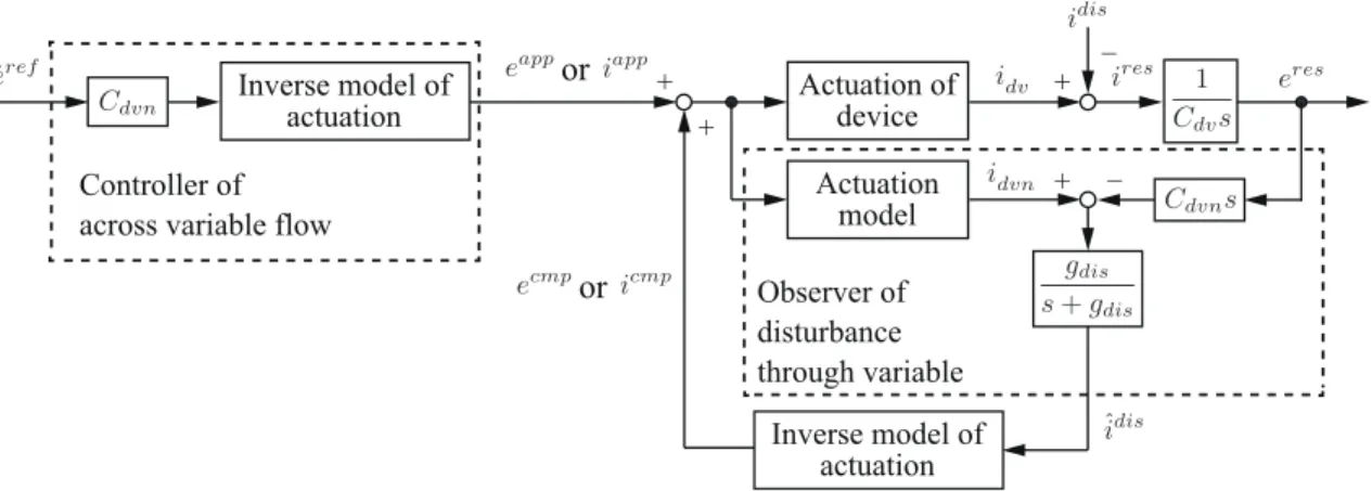
+ + + + _ _ Actuation of device Actuation model Inverse model of actuation Inverse model of actuation or Observer of disturbance through variable or
Fig. 2-5: Robust control of AVF based on observer of disturbance through variable.
2.4
Robust Control of Across Variable Flow
As shown in Figs. 2-3 and 2-4, the through variable generated by the interaction between the device and external environment (represented byiext) can effect on the response of the device. In addition to that, there exist dissipation and leakage of injected energy by R and I elements, and these also change the response of across variable. Realizing the system that is robust against these terms is essential for simplifying and clarifying the strategy of control design.
Addressing the above problems, this study constructs robust AVF control system based on observer of disturbance through variable as shown in Fig. 2-5. Here,gdenotes cut-off frequency of low-pass filter, and superscriptsref,cmpandˆmean reference, compensation and estimated values, respectively. Then, the subscriptsnanddisrepresent nominal value and disturbance observer, respectively. In the control system, command of application (eapporiapp) is generated based on the reference of across variable flow
˙
eref, nominal value of C elementCdvnand inverse model of device actuation. The disturbance observer
estimates the amount of disturbance through variableidisby comparing thei
dvnwith consequent through
variableiresthat brought the response of the device. Here, the disturbance through variable is defined as
idis=iext+ 1 Rdv eres+Idv 1 se res. (2.31)
Supposing thatCdvn=Cdvand actuation model is perfectly identified, the disturbance through variable
is estimated by the observer as
ˆidis= gdis
s+gdis
ST
ST
ST
0
1
C:
Controller of across variable flowPhysical device
Compensation by disturbance observer
Fig. 2-6: Bond graph of robust control of AVF.
C: 1
Fig. 2-7: Approximated bond diagram of perfect AVF control.
The low-pass filter is for reducing the noise amplification by differentiating the responseeres. Note that even when there exist identification errors, the observer estimates those as one of the disturbance terms and compensation is possible. By adding theecmp oricmp as the compensation, the system enhances its robustness against the disturbance through variable. With the use of the compensation, the transfer function from disturbance through variable to device response becomes as
eres idis = 1− gdis s+gdis = s s+gdis . (2.33)
As shown in (2.33), the disturbanceidiscan be suppressed by high-pass filter.
The AVF control system can be interpreted from the perspective of power flow by using bond graph. Fig. 2-6 shows the bond graph of AVF control system. In the physical device part, it is shown that a source absorbs powererefidisand it disturbs the power flowing into the capacitive element. From the bond graph, it turns out that the disturbance observer injects almost same amount of powererefˆidis, and it cancels the power absorption. Moreover, the power(Ccvn−1) ˙ereferef is applied as the supplement
for realizing the response to beeref.
The notable feature of the system is that the device acts for controller as if it had unit value of single capacitive element, as shown in Fig. 2-7. The normalization realized by the internal power injection is beneficial for control system in a sense that the controlled plant is unified to be single1/s in Laplace domain. From this perspective, this dissertation employs the system as a unit for the bilateral control.
2.5
Case of Thermodynamic Systems
In thermodynamic systems, the across and through variables correspond to temperature and entropy flow. However, the entropy flow has difficulty in actual treatment and heat flow is generally taken as an alternative. The graph with the use of the temperature and heat flow is called as pseudo bond graph. In this section, difference between the uses of entropy flow and heat flow is discussed.
The entropy flow is defined as follows
˙ Sres = 1 Tdv d′Qdv dt = 1 Tdv CdvdTdv+pdvdVdv dt , (2.34)
whereS,Q,pandV denote entropy, quantity of heat, pressure and volume (not voltage here), respec-tively. Note that “′” is added at the right hand side of first line of (2.34), since theQis not state quantity actually. Here, Tdv is absolute temperature of device. When solid material is used as thermal device,
the change of volume can be neglected; therefore, the multiplication of temperature and entropy flow becomes equal to heat flow (S˙resTdv =CdvdTdvdt =qres).
The integral of (2.34) yields
Sres = Cdv ∫ Tdv Tamb dT T dt=Cdvln Tdv Tamb ≃ Cdv Tdv−Tamb Tamb =Cdv Tres Tamb , (2.35)
whereTamb denotes ambient temperature which is generally constant and initial value of device
tem-perature. Then,Tres represents the relative temperature fromT
amb. For the approximation of natural
logarithm, first-order Taylor expansion is utilized [100]. In the same manner, the entropy flow can be approximated as ˙ Sres ≃ Cdv Tamb ˙ Tres = 1 Tamb qres. (2.36)
From (2.36), supposing that the variation ofTresis small enough, the entropy flowS˙resis almost
propor-tional to heat flowqres. Moreover, TambCdv can be comprehended as the equivalent C element in generalized system. The assumption is thought to be valid for the haptic instruments, since the temperature range of the application is relatively small (283 K ∼ 323 Kor10◦C ∼ 50 ◦C) among the general thermal