Contents list available at IJRED website
Int. Journal of Renewable Energy Development (IJRED)
Journal homepage: www.ijred.com
Thermodynamic Model of a Very High Efficiency Power Plant based
on a Biomass Gasifier, SOFCs, and a Gas Turbine
P.V. Aravind
a*, C. Schilt
a, B. Türker
b, and T. Woudstra
aaSection Energy Technology, Department of Process and Energy, TU Delft, Leeghwaterstraat 44, 2628 CA Delft, The Netherlands bPPRE, Carl von Ossietzky Universität Oldenburg, Germany.
Article history:
Received May 05, 2012
Received in revised form June 01, 2012 Accepted June 30, 2012
Available online
ABSTRACT: Thermodynamic calculations with a power plant based on a biomass gasifier, SOFCs and a gas turbine are presented. The SOFC anode off-gas which mainly consists of steam and carbon dioxides used as a gasifying agent leading to an allothermal gasification process for which heat is required. Implementation of heat pipes between the SOFC and the gasifier using two SOFC stacks and intercooling the fuel and the cathode streams in between them has shown to be a solution on one hand to drive the allothermal gasification process and on the other hand to cool down the SOFC. It is seen that this helps to reduce the exergy losses in the system significantly. With such a system, electrical efficiency around 73% is shown as achievable.
Keywords: biomass gasification, efficiency, exergy, gas turbine, heat pipe, solid oxide fuel cell
* Corresponding author. Tel.:+31 (0) 15 27 83550 E-mail: [email protected]
1. Introduction
Gasification can be employed to produce gaseous fuels from solid fuels such as coal and biomass. The gaseous fuels thus produced could be used as fuels for Solid Oxide Fuel Cell – Gas Turbine (SOFC-GT) systems if sufficiently cleaned. By using biomass as a gasifier feedstock, sustainable electricity production can be achieved. SOFC-GT systems operating on solid fuels are expected to achieve high efficiencies in electricity production [1-4] when compared to the present day power plants based on similar fuels. Based on thermodynamic calculations, it was shown that natural gas fuelled SOFC-GT systems can reach relatively high electrical efficiencies of 60 - 80% [2, 5]. Proper heat management, especially when using the heat produced from the electrochemical reactions for the reforming of the carbonaceous fuel such as natural gas, helps to achieve such high efficiencies. Such opportunities exist for efficient heat management when biomass, which is a carbonaceous fuel, is used as a fuel for SOFC-GT systems. System calculations carried out at Delft and Imperial College have shown that such systems may potentially lead to electrical efficiencies above 60%
from solid fuels [6-8]. This paper presents a system with efficient heat management to achieve very high efficiencies in gasifier-SOFC-GT systems.
This study presents the results of a thermodynamic analysis of an improved gasifier-SOFC-GT system at several MW power levels. The models are based on the 100 kW base-case system as developed earlier in the work of Aravind et al. [1] which presented net electrical efficiencies around 54% for 100 kW electrical power production. As far as possible, similar input parameters are assumed for the system components, in order to see the effect of reconfiguring and scaling up the system on efficiency improvement. The focus during this study is on electricity production.
2. Descriptions of the Subsystems Employed
114
126 125125 124124 123123 122122
121
103 102102 101101
611
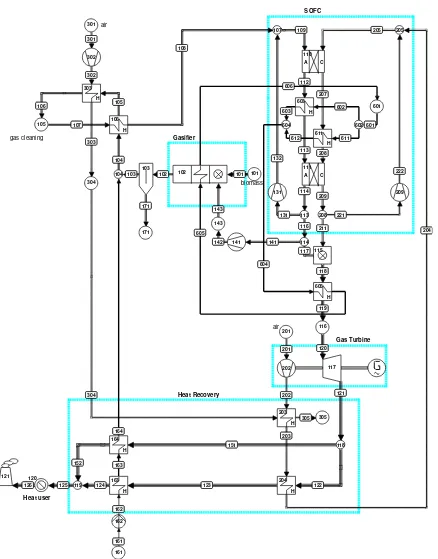
Fig. 1 Process flow diagram of the improved biomass gasifier-SOFC-gas turbine system
Clean biosyngas is fed to the two SOFCs connected in series operating at around 900-1000°C, part of the anode and cathode gas is recycled to maintain the SOFC inlet temperature at 900°C. Since not all the fuel is utilized in the fuel cells (both the SOFCs combined together oxidize 85% of the syngas produced), anode gas is combusted using the cathode outlet gas before the turbine. Exhaust is used to preheat the cathode air flow
2.1 Biomass Gasification
Gasification involves thermal conversion of organic solid fuels into a gaseous fuel, consisting primarily of hydrogen (H2), carbon monoxide (CO) carbon dioxide (CO2), methane (CH4), ethane (C2H6), water (H2O) and nitrogen (N2). The composition is dependent on the gasifying agent, the type of the gasifier and the operating conditions. If air or oxygen (O2) is used as an oxidant, the oxidation reactions can supply the heat necessary for the endothermic reactions in the gasifier, thus no external energy supply is needed (autothermal gasification). If air is used as the oxidizing agent, the biosyngas will contain significant amounts of nitrogen. In principle it is inefficient to heat up an inert gas, but in the gasifier-SOFC-GT system, it may reduce the required cooling air at the cathode of the SOFC. Due to the high nitrogen content in the biosyngas, air gasification results in low heating values of 4-6 MJ/m3n. Steam and oxygen gasification produce gas streams with higher heating values of 10-18 MJ/m3n [9]. However steam gasification is an allothermal process which requires additional heat.
2.2 Heat Pipes
Electrochemical fuel oxidation in fuel cells often produces heat, which is normally removed by the cathode flow. Steam/CO2 gasification is allothermal and requires heat. Integration of the allothermal gasification process and the exothermal fuel cell will probably decrease 1) the exergy losses in the gasifier and 2) reduce the required air flow at the cathode, resulting in a higher system performance. Integration of those two processes can be done by heat pipes. Heat pipes utilize vaporizing liquid in order to create high heat fluxes from any heat source, in this case the SOFC, to a heat user, in this case the gasifier, where the endothermic gasification reactions take place. Recently the
EU-funded project BioHPR was successfully completed,
using heat pipes in gasifiers producing biosyngas with a high lower heating value (LHV). Mole percentages of 40% H2, 20% CO and 5% CH4 in the biosyngas are reported [10].
2.3 Solid Oxide Fuel Cell
We propose a construction using SOFCs in series with the heat pipes placed in between for intercooling. Instead of one SOFC as in [1] we now use two SOFCs. The heat is transferred to the heat pipes from first SOFC outlet pipes.
2.4 Other Components
Other system components are not described here as they are modeled as explained in the base case in [1].
3. System Configuration & Model Assumptions
The system is modeled using Cycle Tempo, and in-house software developed at Delft University of Technology for thermodynamic calculations for power plants. All the equations used for the calculations described here are available at the Cycle Tempos website [11].
3.1. Biomass gasification and gas cleaning
Most of the assumptions regarding the gasifier and the gas cleaning for modeling purposes are same as the ones given in [1]. Differences are described below. The biomass composition, for casuarina, is selected from the Phyllis database provided by Energy research Centre of the Netherlands (ECN) [12]. In order to have 15% wt moisture content, the biomass composition is corrected. A lower heating value of 15.500 kJ/kg is considered for the biomass. The biomass is fed to the gasifier at 25°C and at the gasification pressure. In the system, the biomass input is kept at a constant flow rate of 11 kg/s. The gasifier, with an outlet temperature of 800°C, is modeled as an equilibrium reactor and carbon conversion is 98% complete. Unconverted carbon is bypassed in the gasifier for the calculations (for the reference case, the 100 kW system published before [1], carbon conversion was 95%. Also 2 mole % of methane is bypassed in the gasifier [1, 2]. The gasifier is expected to have a section with catalytic reforming before the outlet and it is assumed that this is sufficient for reaching near equilibrium gas compositions and hence no significant amount of tar is considered as produced. The biosyngas is cleaned near the gasification temperature with a lowest cleaning temperature of 600oC as in the base case in [1]. After the dust and tar cleaning, the syngas is cooled down to 600°C for HCl and H2S removal. Steam is added before cooling down the gas. Carbon deposition tendency with the gas before cooling down is evaluated using Facstage, a software for thermodynamic equilibrium calculations [13]. It is assumed that the gas cleaning devices employed in the system do not change the composition of fuel gas except for the contaminants. In the process flow, they are considered to cause pressure drop. It is assumed that no heat is lost to the environment.
3.2. SOFC- Gas Turbine System
H2, CO and CH4 is combusted with cathode gas in the combustor. The power output of the gas turbine is dependent on the mass flow of the flue gas and the enthalpy difference between the entering and leaving flow. The amount of flue gas is mainly determined by the cooling cathode flow. However if the cooling flow is decreased, the turbine inlet temperature (and thus inlet enthalpy) is increased as long as the air available is more than enough for the stoichiometric combustion. The flue gas that coming out from the gas turbine is further used to heat up cathode air and producing steam.
3.3. Heat Pipes
The heat is transferred to the heat pipes from first SOFC outlet pipes and after the combustion chamber. Hot product gasses (1000°C) are cooled down to about 900°C before they enter the second fuel cell. The heat is transferred by the heat pipes to the gasifier. In the current models, for modeling reasons, we used two heat exchangers and steam circulation for heat transfer. This modeling approach for heat pipes does not affect the exergy loss as long as the temperatures are equal to the temperatures existing in heat pipes in practice. In the modeled system, just an amount of heat is transferred independent of the heat pipe working fluid. The heat pipes are placed in between the two fuel cells with the
first one having a fuel utilization of 69% with the rest of the fuel being converted in the second fuel cell to achieve a combined fuel utilization of 85% with respect to the fuel gas stream after gas cleaning. Heat pipes are also proposed to carry a part of the heat from the combustion products to the gasifier.
4. Results and Discussion
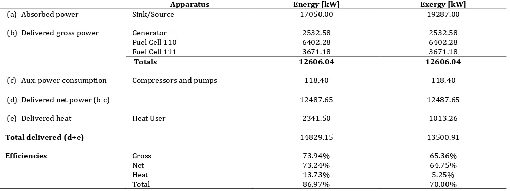
By scaling up the reference case model and implementing anode gas recycling for gasification instead of air and heat pipes for exchanging heat between SOFC and the gasifier, the net system efficiency is around 75% if AC/DC conversion losses are ignored and around 73% if AC/DC conversion losses are included. Thermodynamic evaluation had shown no carbon deposition tendency while gas is cooling till 600oC, the lowest gas cleaning temperature. The results obtained from the present system are compared with the reference case system results from [1]. For both the cases, the reference case and the present case, the largest amount of exergy is lost in the gasifier. The percentage exergy losses in the gasifier in the present system comes down to around 13% when compared to the percentage exergy losses in the gasifier in the reference system which is around 25%. Table 1 gives an overview of the performance of the present system.
Table 1
System performance of improved system with anode recycling and heat pipes
Apparatus Energy [kW] Exergy [kW]
(a) Absorbed power Sink/Source 17050.00 19287.00
(b)Delivered gross power Generator 2532.58 2532.58
Fuel Cell 110 6402.28 6402.28
Fuel Cell 111 3671.18 3671.18
Totals 12606.04 12606.04
(c) Aux. power consumption Compressors and pumps 118.40 118.40
(d)Delivered net power (b-c) 12487.65 12487.65
(e) Delivered heat Heat User 2341.50 1013.26
Total delivered (d+e) 14829.15 13500.91
Efficiencies Gross 73.94% 65.36%
Net 73.24% 64.75%
Heat 13.73% 5.25%
Total 86.97% 70.00%
Heat is still available before that stack amounting to around 13% of the input chemical energy at 393oC which can be used for producing electric power using a bottoming cycle (such as a steam cycle). Also 2% of the carbon bypassed in the gasifier as unconverted carbon might be used for power production under certain conditions and hence the systems presented here have the potential to achieve system electrical efficiencies closer to 80% if modified. This is comparable to the
5. Conclusion
The system calculations performed indicate that high system electrical efficiencies around 73% are achievable in gasifier-SOFC-GT systems with still the scope for system efficiency improvements by a few percent remaining. Detailed system calculations and further modified system models will be presented in later manuscripts. The results indicate that the development of gasifier-SOFC-GT systems warrants significant attention from the scientific and engineering communities.
Acknowledgement
This manuscript is mainly based on the models developed with MSc research of B. Turker (2008) and C Schilt (2010) under the supervision of the first and the last authors (the models were refined later by the first and last authors). The authors thank Dr. K. Blum, PPRE, Carl von Ossietzky Universität Oldenburg for the co-supervision of B Turker. Ms Eva Promes is thanked for the writing assistance provided.
References
[1] Aravind PV, Woudstra T, Woudstra N, Spliethoff H (2009) Thermodynamic Evaluation of Small-Scale Systems with Biomass Gasifiers, Solid Oxide Fuel Cells with Ni/GDC Anodes and Gas Turbines. Journal of Power Sources 190(2):461-75.
[2] Aravind PV (2007) Studies on High Efficiency Energy Systems Based on Biomass Gasifiers and Solid Oxide Fuel Cells with Ni/GDC Anodes. PhD Thesis, Delft: TU Delft.
[3] Toonssen R, Sollai S, Aravind PV, Woudstra N, Verkooijen AHM (2011) Alternative System Designs of Biomass Gasification SOFC/GT Hybrid Systems. International Journal of Hydrogen Energy 36(16):10414-25.
[4] Grol. E. NETL (2009) Technical Assessment of An Integrated Gasification Fuel Cell Combined Cycle with Carbon Capture. Energy Procedia 1:4307-13.
[5] Bosch KJ, Woudstra N, van der Nat KV (2006) Designing Solid Oxide Fuel Cell Gas Turbine Hybrid Systems using Exergy Analysis. The 4th International Conference on Fuel Cell Science,
Engineering and Technology 2006, Irvine, CA.
[6] Turker B (2008) Thermodynamic Modelling and Efficiency, Improvement of Gasification, SOFC, and Combined Cycle Systems. MSc Thesis, University of Oldenburg.
[7] Schilt C (2010) Thermodynamic Modeling and Optimization of Biomass Gasifier-SOFC-Gas Turbine Systems, MSc Thesis, TU Delft.
[8] Sadhukhan J, Zhao Y, Shah N, Brandon N (2010) Performance Analysis of Integrated Biomass Gasication Fuel Cell (BGFC) and Biomass Gasication Combined Cycle (BGCC) Systems. 2010;65(6) Chem Eng Sci. 65(6):1942-54.
[9] Seitarides T, Athanasiou C, Zabaniotou A (2008) Modular Biomass Gasification-based Solid Oxide Fuel Cells (SOFC) for Sustainable Development. Renewable and Sustainable Energy Reviews 12(5):1251-76.
[10] Karellas S, Karl J (2007) Analysis of The Product Gas from Biomass Gasification by Means of Laser Spectroscopy. Optics and Lasers in Engineering 45(9):935-46
[11] www.cycle-tempo.nl. [12] http://www.ecn.nl/phyllis [13] www.factsage.com.