THE COMBINATION OF LASER SCANNING AND STRUCTURE FROM MOTION
TECHNOLOGY FOR CREATION OF ACCURATE EXTERIOR AND INTERIOR
ORTHOPHOTOS OF ST. NICHOLAS BAROQUE CHURCH
B. Koska a, *, T. Křemen a
a
CTU in Prague, Faculty of Civil Engineering, 166 29 Prague 6, Czech Republic - (bronislav.koska, tomas.kremen)@fsv.cvut.cz
KEY WORDS: Laser Scanning, Structure from Motion, Texture, Orthophoto, Orthoimage, Photogrammetry
ABSTRACT:
Terrestrial laser scanning technology is used for creation of building documentation and 3D building model from its emerging at the turn of the millennium. Photogrammetry has even longer tradition in this field. Both technologies have some technical limitations if they are used for creation of a façade or even an interior orthophoto, but combination of both technologies seems profitable. Laser scanning can be used for creation of an accurate 3D model and photogrammetry for consequent application of high quality colour information. Both technologies were used in synergy to create the building plans, 2D drawing documentation of facades and interior views and the orthophotos of St. Nicholas Baroque church in Prague. The case study is described in details in the paper.
1. INTRODUCTION
The relation called 2D homography with computation method direct linear transformation (Hartlay, 2003) a (Krauss, 2007) is used in the case of photogrammetry/computer vision. The main technological limitation of the method is depth of an object. The maximum error in orthophoto is: position (at the margin of the image) in project units
w = camera sensor width
f = camera focal length
∆yM = maximum object orthogonal distance from the main plane, which causes allowed error ∆rM. ∆rM can be significant and often has similar size as ∆y
M
Another error is caused by not parallelism of the main camera axis and the normal vector of the main object plane. More information and numerical examples of the issue is presented in (Krauss, 2007). It’s obvious that it is impossible to create an orthophoto like one that can be seen on the Chyba! Nenalezen zdroj odkazů.7 using this method (the left tower is more than ten meters further than the right tower).
In the laser scanning case we should talk about an orthoimage or an orthoview, but not about an orthophoto. An orthoimage is an orthogonal view on a point cloud, which has a colour based on the intensity of the returned signal see Fig. 1 or from an image. An orthoimage has a resolution limited by resolution of
the point cloud. Another disadvantage of an orthoimage is impossibility of colour blending (Xu, 2010).
Figure 1. An orthoimage example
It is also important to remark that some laser scanners (mostly those based on the phase-sift distance meter), doesn’t include any camera. Some laser scanners include a camera with poor quality and resolution. Only a few laser scanning systems contains high quality camera or can use easily an external high quality camera (often DSLR - Digital Single-Lens Reflex) e.g. Riegl and Optech systems.
Some methods for improvement orthoimage quality were published (Řezníček, 2011).
Combination of the laser scanning technology and photogrammetry seems profitable from the characteristic stated above. Laser scanning can be used for creation of an accurate 3D model and photogrammetry for consequent application of high quality color information. The structure from motion
algorithm (SFM) (Snavely, 2006) can be used for effective orientation (pose estimation) of images.
The whole process is composed of:
1. Creation of an accurate and detailed 3D polygonal model from the laser scanning data.
2. Images external orientation determination using SFM method.
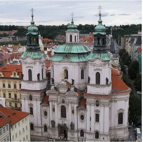
The object of interest was St. Nicholas Church which is situated on Old Town square in the center of Prague see Fig. 2. The church was built during 1732-37.
Figure 2. Image of St. Nicholas church main facade
The project task was creation of 2D building plans, 2D drawing documentation of facades (exterior) and nave views (interior) and high resolution orthophotos of the same parts. The Surphaser 25HSX. Laser scanner standpoints were placed on the ground, on the nearby buildings and on the roof of the SONY 16/2,8 SEL. All camera + lens set were calibrated.
2.3 Processing of Laser Scanning Data
2.3.1 Point Cloud
We worked with point clouds in the first phase and we used software Leica Cyclone. At first transformations from individual standpoints to the Czech national coordinate system S-JTSK were performed. The final point cloud model had about 170 million points from Lecia HDS3000 laser scanner (mostly exterior) and about 2500 points from Surphaser scanner (mostly in interior). Then the reduction to average point spacing 10 mm were carried out and we got point cloud with about 100 million points (approximately half point in interior and half in exterior of the church).
2.3.2 Mesh
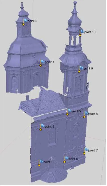
The next step was creation of triangular network model (mesh) in the Geomagic Studio software. Mesh model was created individually for every façade or interior view because of high volume of the data. All details had to be accurately modelled to get correct texture mapping results (statues, decorative column heads, window decorations, …). This work was the most time consuming part of the whole process. Creation of one façade mesh model took about 30 hours of man-hours. The mesh size had to been reduced anyway for comfort work with the model. The “intelligent” tools for points/triangles reduction from Geomagic Studio were used. They reduce density mostly in the parts with low surface curvature (walls without decoration). Resulting meshes of facades had about 10 million triangles. The results of the west church façade are presented for illustration see Fig. 3 and 4.
Figure 3. Church west façade mesh
2.4 Processing of Images
Photographs can be processed in any structure-from-motion software (further called SFM). This process is also often called sparse reconstruction from images. Software/programs for the purpose are e.g. Bundler (Snavely, 2006), VisualSFM, Photomodeler and Agisoft PhotoScan.
2.4.1 Transformation
In the next step the used software must support transformation to the coordinate system defined by control points. Control points must be identified in georeferenced point cloud/mesh and on relevant images. The software supporting this feature is e.g. VisualSFM, Photomodeler and Agisoft PhotoScan.
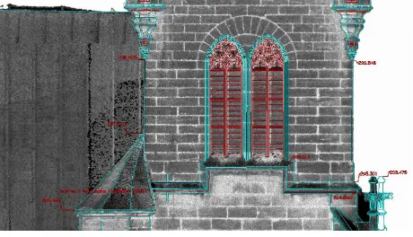
Example of control points choice on the west façade can be seen on Fig. 5. The control points were selected in corners of façade decorations and features e.g. see Fig. 6. Standard deviation of transformation for west facade is 26 mm and maximum residual is 37 mm.
Figure 5. Control points selection on the west façade
Figure 6. Control point n. 3
2.5 Texture Mapping and/or Orthophoto Generation
The next step is images mapping on the 3D model triangles for orthophoto generation or model texturing. Only Photomodeler and Agisoft PhotoScan from previously named software can do the task. The precondition for the step is possibility of extern mesh import to the software. We used Agisoft PhotoScan for all steps in the project.
There exist two possibilities how to continue in the process in general. The first is direct orthophoto generation, but not all software supports it. The second possibility is creation of texture for the model, saving the model with texture in appropriate format (e.g. vrml or obj) and creation of an orthophoto by generation orthogonal view with high resolution in suitable software. The software MeshLab or Geomagic Studio can be used for the task.
PhotoScan supports two options for orthophoto generation or texture mapping. They are called “Average” and “Mosaic”. Implementation details of these methods are not public because PhotoScan is proprietary software, but it is clear from the name that “Average” method uses weighted average pixel colour value from all available photos for texture/orthophoto pixel colour.
The method “Mosaic” contrary use for every pixel of texture/orthophoto only one input photo and it uses it for bigger parts of surfaces than one pixel. Transition areas from one input image to the neighbor input image are blended. Personal experience is that unknown algorithm for “best” image selection doesn’t work perfectly and sometimes chooses un-optimal input images regarding image spatial resolution or big angle between camera axis and surface normal. That’s why own texture mapping solutions were suggested and tested. It has the exact solution for segmentation of a model and for the “best” image selection for each patch, which is based on maximum spatial image resolution (combination of camera center distance from patch and patch normal to camera axis angle). Because this texture mapping solution was not released to public yet, it is not described in more detail in the paper.
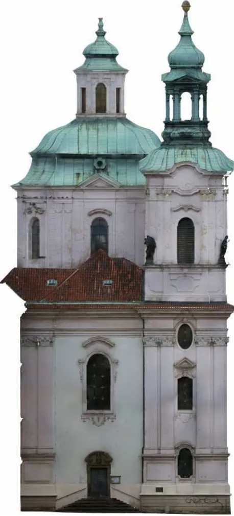
Now, we can get back to the PhotoScan orthophoto generation tools. The results from “Average” and “Mosaic” method don’t differ a lot in the low resolution view like you can see on Fig. 7.
Figure 7. Orthophoto of west facade
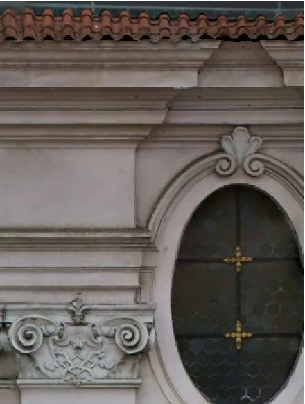
If you get to the pixel level (pixel size is 5 mm), you can see differences in quality of details e.g. on window decoration or on roofing see Fig. 8 and Fig. 9. That’s why we used “Mosaic” method which is of a better quality.
Figure 8. Mosaic orthophoto detail
Figure 9. Average orthophoto detail
2.5.1 Photo masking
The next most time consuming part of the whole process was
photos, where are visible objects which are not modeled in used 3D model. If these objects are not masked, they can cause significant errors in final texture/orthophoto. These objects can be in motion or static. In motions objects were e.g. people, flying birds, cars etc. in our project. Static object were e.g. street lamps, cables, sitting birds etc. For illustration see Fig. 10 and 11.
Figure 10. Masking of uninterested objects in exterior
The most problematic parts from the masking point of view were interior areas. There is a richly decorated chandelier in the middle of the main nave. There are also a lot of hanging cables for illumination and audio technique and church equipment see Fig. 11.
Figure 11. Masking of uninterested objects in interior
3. CONCLUSION
The new method for high resolution orthophoto creation for objects with very ragged surface is presented and described in the paper. The method is based on combination of the laser scanning and the structure-from-motion technology.
The most time consuming part of the method is manual work on creation of accurate and detailed 3D model from laser scanning data and masking of objects, which are not part of the 3D
Created accurate high resolution orthophotos can be used for direct study and measuring. They can be also used for creation of 2D drawings documentation of facades and interior views. Using orthophotos for the task is more suitable than standard using of point clouds, because data volume is much smaller and interpretation of the details is more comfortable.
4. REFERENCES
Hartlay, R., Zisserman, A., 2003. Mulitple View Geometry in computer vision. Second Edition. Cambridge University Press, Cambridge.
Krauss, K., 2007. Photogrammetry – Geometry from Images and Laser Scans. Second Edition. De Gruyter, Berlin..
Řezníček, J., 2011. Overview of the Methods for Ortho-Image Generation from the Coloured Laser Scan Dataset. XXIIIth International CIPA Symposium, Prague, Czech Republic.
Snavely, N., Seitz, S. M., Szeliski, R., 2006. Photo Tourism: Exploring image collections in 3D. ACM Transactions on Graphics (Proceedings of SIGGRAPH 2006).
Xu, L., Li, E., Li, J., Chen, Y., Zhang, Y., 2010. A General Texture Mapping Framework for Image-based 3D Modeling.
17th IEEE International Conference on Image Processing (ICIP).
5. ACKNOWLEDGEMENTS
This research has been supported by SGS grant “Optimalization of acquisition and processing of 3D data for purpose of engineering surveying”.