Procedia Engineering 125 ( 2015 ) 838 – 842
1877-7058 © 2015 The Authors. Published by Elsevier Ltd. This is an open access article under the CC BY-NC-ND license (http://creativecommons.org/licenses/by-nc-nd/4.0/).
Peer-review under responsibility of organizing committee of The 5th International Conference of Euro Asia Civil Engineering Forum (EACEF-5) doi: 10.1016/j.proeng.2015.11.050
ScienceDirect
The 5th International Conference of Euro Asia Civil Engineering Forum (EACEF-5)
Beam column and footings connection of simple prefab housing
Sentosa Limanto
a,*, Johanes Indrojono Suwono
aaPetra Christian University, Jl.Siwalankerto 121-131, Surabaya 60236, Indonesia
Abstract
To meet the urgent need for transmigration and to displacements due to natural disasters, prefab housing system is required for fast construction. This study proposed a joint system to connect footings, concrete column / pedestal, and the tie beams. From four types of connections two were deemed appropriate. A prototype, 2×2×2 m, was built for this purpose and tested for the reliability of the connections. It appears that the connection could resist a horizontal force of 10% the column load and able to withstand a differential settlement of 2 cm. Erection with simple tools to assemble the components of the prototype only needs less than 6 hours by three laborers. Factory made components will speed up the installation.
© 2015 The Authors. Published by Elsevier Ltd.
Peer-review under responsibility of organizing committee of The 5th International Conference of Euro Asia Civil Engineering Forum (EACEF-5).
Keywords:footings;column pedestal; tie beam; connection system; joints; prefab concrete; simplehousing.
1.Introduction
For a mass product of small housings, prefabricated building components will be needed. This requires an appropriate joint system to connect the components in a fast and secure way. Inspired by Ciarlini’s invention [1], a joint system was designed and proposed to meet the requirements for a fast and simple construction. The joints were connections of footings - column pedestal – tie beams, and column – ring beams. To know the reliability of the proposed joint system, a prototype was built in-situ and tested to resist against horizontal forces and differential settlements.
The prototype measured 2×2×2 m concrete frame manually mixed and casted, and constructed with simple implements. The idea is, that when the prototype passed the tests certainly with manufactured prefabs the safety factor will increase.
* Corresponding author: E-mail address: [email protected]
© 2015 The Authors. Published by Elsevier Ltd. This is an open access article under the CC BY-NC-ND license (http://creativecommons.org/licenses/by-nc-nd/4.0/).
2.The main components
It was observed from several low cost housing models, that the total load on the columns does not exceed 30 kN [2, 3]. It is common that the bearing ground can safely carry a stress of 3 kN/m², hence a square footing of 1×1 m² will be sufficient. With 12 cm thickness the footings weighed no more than 3 kN, easy to be hoisted manually with winch and pulley.
Cross section of the tie beams is 10×20 cm² and the length shall not more than 3 m to minimize its reinforcement. The pedestal and columns section measured 20×20 cm². The top of the column was casted with four corbels to provide a robust connection with the ring beams. The height of the column should not be more than 4 m to prevent slenderness and difficulties during erection.
All the components were made manually with a volume mix of 1 (gravel): 2 (sand): 3 (cement) and casted in wooden formworks. The least compressive strength of standard concrete cubes was found greater than 15.5 MPa, sufficient for footings design [4].
3.The bottom connection
At the center the footings a square slot was made for the column pedestal to be plugged in. From four trials, two types of footings – pedestal connection were selected, namely type III and type IV, as seen in the following Fig. 1.a,b. The models were adapted from Ref. [3] with some modifications.
(a) (b)
Fig. 1. Footings and column pedestal (a) type III (b) type IV
3.1.Type III
Besides the slot at the center, in type III footing, other slots were made to provide the tie beam connection. In this case the beam was constructed with a stub that fits to the slot. Four slots were made for this purpose, anticipating expandable module. Fig. 2 shows the installation of the type III footings.
The advantage of this type is its simplicity in connecting the column pedestal and tie beams. However, it is only applicable for square or rectangular modules. Dimensions of the stub of the beam were designed to withstand a
horizontal force of 10% the column’s load, i.e. 3 kN. The allowable shear strength of the concrete was taken as Wbp =
206 √Vbk’, and with Vbk’ = 15 MPa, comes to Wbp = 797 kPa.
3.2.Type IV
The type IV footings have a square annulus where the pedestal could be plugged in. The pedestal has four consoles (short beam) with pin joints to connect the tie beams. The size of pin was 28 mm in diameter and 20 cm length, half of it embedded in the console. With this size the pin could resist the horizontal force even embedded in the low compressive strength concrete. The pin makes the tie beams able to tolerate non-perpendicular deviations. Fig. 3 shows installation of type IV footing installation.
Fig. 3. Pedestal of type IV footings
3.3.Horizontal load test
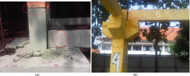
Connection of the tie beams with the footings were tested in-situ. A hydraulic jack was placed between two footings to push them apart till the concrete show significant cracks. Fig. 4 shows the assembly of the horizontal load test and the cracks in type IV footing
(a) (b)
With the type III connection, significant cracks occured after a force about 7.2 kN, whereas with type IV (pin joint) the cracks start after a force of 5 kN. At 3 kN horizontal force, the concrete components remained still intact.
4.The top connection
The column is inserted in the pedestal. The top of the column is fig d in Fig. 5 [5]. This type was chosen from three proposed column connections. The ring beams were constructed similar with the tie beams of type III. The corbels have slots for the insertions of the ring beams. This type of corbel enables expansion of the module.
(a) (b)
Fig. 5. The top part of the column (a) side view (b) plan
5.The prototype
The module was built with the components of type III and type IV (Fig. 6). The reason to built a prototype is to know the time necessary to assemble the components, and whether the proposed connections can withstand any differential settlements. For this purpose one of the footings was raised and dropped. Time for erection was relatively fast. With one supervisor and three labours, it took less than 6 hours to assemble the prototype.
The connections of the components were still intact when one of the footings was raised to 2 cm or about 1/ 100 span. Cracks in the components initiated and dislocation of the ring beams occurred when the footings was further raised to 4 cm.
(a) (b)
6.Conclusion
x On common ground prefabricated low cost housings could be founded on 1×1 m² footings connected by tie beams. The two proposed connections are feasible for prefab low cost housings. With manually casted concrete components the connections could withstand a horizontal force of 1/
10th the column load and a tilt of 1/100 span.
x Erection with simple tools to assemble the components of the prototype only needs less than 6 hours by three laborers. Factory made components will speed up the installation.
x With careful and precise manufacturing of the prefab components, the connections will faster to be assembled and give greater resistance to detrimental deformations.
References
[1] Ciarlini, L. (1952) Reinforced concrete column, bracket, and beam joints, Patent no: 2.613.146, November 18, 1952.
[2] Wuisan, D. and Raharjo, C. (2012). Sambungan Pada Pondasi Pedestal .Kolom dan Sloof Beton bertulang untuk Rumah Sederhana Satu Lantai di Surabaya. Undergraduate Thesis no: 21011858/SIP/2012, Civil Engineering Department, Petra Christian University Surabaya, Indonesia.
[3] Luden, A.S, and Prakasa, R. (2012). Sistem Interlocking Pondasi Tapak Pada Rumah Sederhana Satu Lantai. Undergraduate Thesis Civil Engineering Departement Petra Christian University Surabaya, Indonesia.
[4] Department of Public Works Indonesia (1971), Peraturan Beton Indonesia 1971.