Read this manual carefully before using the equipment.
All operations on the equipment must be carried out by specialised personnel who must be fully aware of all the safety warnings.
The manufacturer is not responsible in any way for the use of the information contained in this manual or the products referred to.
As the products are constantly being developed, this manual may be updated without prior notice.
All the rights for this document are reserved.
Partial or total reproduction of this manual is only permitted if authorised by the manufacturer.
CONTENTS
Chapter 1 :
Introduction
1.1 Introduction: using the computer 1.2 Temperature reading and adjustment 1.3 Speed reading and adjustment 1.4 Modifying data
Chapter 2 :
Operating pages
2.1 Adjusters page 2.2 Histogram page 2.3 Recorder
2.4 Hole management page 2.5 Writing firing formulas 2.6 Changing firing formulas 2.7 Adjuster Parameters-Trends 2.8 Firing curves
2.9 Autoset 2.10 Alarms
2.11 Production-Consumption data 2.12 Operator messages
2.13 ERO MCL Termoadjusters 2.14 ERO FMC-PMW Termoadjusters
2.15 ERO TFS Servo – TFS mA Termoadjusters 2.16 ASCON XM Termoadjusters
2.17 ASCON XC-XP-XS Termoadjusters
2.18 ASCON M9 Servo – M9 mA Termoadjusters 2.19 YUMO DICON-SM Termoadjusters
Chapter 3 :
Configuration pages
3.1 Configuration menu 3.2 Adjuster configuration
3.3 Counter configuration 3.4 Inputs-Outputs
3.5 Alarm configuration 3.6 Timers-Memories selection 3.7 Inputs-Outputs Check 3.8 Start-up
3.9 Clock
3.10 Password configuration 3.11 Language selection 3.12 Maintenance
Chapter 4 :
Maintenance and assistance
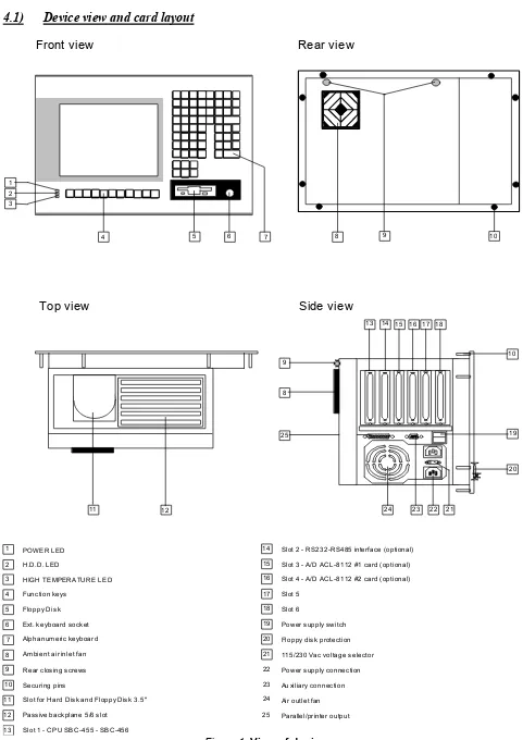
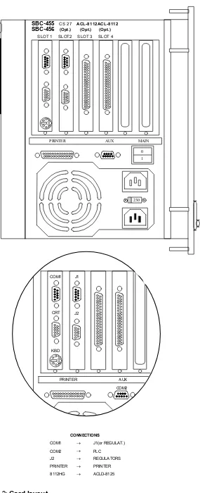
4.1 View of device and card layout 4.2 Description of device
4.3 Conformity of device 4.4 CPU card setup
4.5 Environmental requirements 4.6 Ordinary maintenance
4.7 Extraordinary maintenance
4.8 Making backup files using a floppy disk 4.9 Restoring files using a floppy disk 4.10 Changing or formatting the hard disk 4.11 No image on the screen
4.12 Printer not functioning
1.1) Introduction: using the computer
The EWS-600 computer is used for detecting and adjusting the characteristic process dimensions (temperatures,
pressures, speeds) of ceramic kilns.
The base configuration envisages the handling of a single kiln and can be expanded (by adding input-output modules) to handle a second kiln.
The objective of the computer is firing of the infeed material using FORMULAS, set by the user, which can be called up at any time, with the possibility of minimising downtime caused by product changes and ordinary maintenance of the kiln.
The computer can be used to display the graphs of the formulas for the cycle times and the distances in the kiln, which makes it possible to design a firing formula based on the resulting graph or by comparison with other formulas.
A part for handling PRODUCTION and CONSUMPTION data can be used for periodic detection of the material produced and the heat consumption, which informs you about the performance of the kiln and allows you to improve it, if required.
The computer can also be used to save the historical trends of the process dimensions detected (temperatures-pressures-speeds).
Press one of the keys 0 ... 9 to open the corresponding page.
Return to the MAIN MENU using the keys F10 Esc .
In every display page, the last line is dedicated to a display of the COMMANDS relative to the page. Some COMMANDS vary in accordance with the page in which they are located (the last line identifies the meaning for the current page) while some commands do not vary.
The commands which do not vary are the following:
F10 Esc Return to MAIN MENU
F5 Print the page in alphanumeric mode F6 Print the page in graphic mode
1.2)
Temperature reading and adjustment
The temperatures in the kiln are reset by THERMOCOUPLES installed in the kiln. The reading methods depend on whether the temperatures are adjusted or not:
1) DETECTED and ADJUSTED temperatures
The temperatures are read and adjusted with TERMOADJUSTERS connected by a serial line to the computer. The
type of communication depends on the type of termoadjusters installed.
The computer RECEIVES from the TERMOADJUSTERS:
- The temperature detected - % servomotor (0-100)
The computer TRANSMITS to the TERMOADJUSTERS:
- The temperature set
2) Temperatures DETECTED ONLY
The temperature is READ on the basis of analog inputs connected to the PLC or the computer.
1.3)
Speed reading and adjustment
The SPEEDS are read by digital inputs connected to sensors installed on the roller drive.
The digital inputs are connected to the PLC which calculates the speed of the roller drives present in the kiln and
ADJUSTS on the basis of the computer settings.
1.4) Modifying
data
The operator can use the EWS-600 computer display pages to modify a certain number of data items.
Data items are modified as follows:
- Use a function key (usually F2 F3 ) to access the MODIFY STATE.
This key is shown in the last line of every page where you can modify data. While you remain in the MODIFY STATE, the modifications are not operative.
- After modifying, use F10 to exit the modify state.
- When you exit, the computer asks for confirmation with the following message:
Data correct ? (yes = ENTER)
- Press Enter to make the modifications operative.
- Press any other key to reset the values set before you entered the modify state.
2.1) Adjusters
page
In the MAIN MENU, press 0 to access the ADJUSTERS PAGE, where you can display the main temperature, pressure and speed data.
The following page is displayed:
For a number of TEMPERATURE-PRESSURE channels between 1 and 36, the following data is displayed:
- N. Adjuster number.
- DESC. Adjuster description
- R.V. Value detected - S.P. Value set
- % Percentage 0-100 modular - A Alarm state
For a number of SPEED channels between 1 and 20, the following data is displayed:
- T. Roller drive number
- R.V. Speed value detected
- S.P. Value set
The temperature-pressure set points can be modified using F2 , while the speed set points can be modified using
F3 .
When you exit modify state, the computer automatically prints the variations made if the printer is ON (see Par. 3.7).
The temperature-pressure set points are then sent by the computer to the TERMOADJUSTERS, while the speed set
points are used to adjust the roller drive speed.
On the EWS-600 computer, when you change a temperature-pressure set point, a internal set point update program used for adjustment (called DYNAMICSET POINT) is started.
200
FINAL SET POINT and DYNAMIC SET POINT are normally the same.
When you decide to change the SET POINT (e.g. from 400 to 1000), if the adjustment immediately starts to work on 1000, there will be an error as, for a certain time, it would keep the gas valves in the FULLY OPEN position.
To prevent this, the adjustment is made to the DYNAMIC SET POINT which is varied automatically by the computer
once a minute until its value is the same as the FINAL SET POINT.
The UP or DOWN speed of the dynamic set point is normally between 0.1 and 4.0 degrees/min.
Note that the computer continually sends the DYNAMIC SET POINT to any instruments connected by serial line.
When you change the set point in the adjusters page of the computer, remember that, for a certain time, the computer will send the intermediate set point values to the instruments until the DYNAMIC SET POINT value has reached the
In the ADJUSTERS PAGE, the temperature values detected are displayed in a different colour, in accordance with the
STATE of the adjuster itself.
- LOCAL - REMOTE (colours PURPLE – GREEN):
In the LOCAL or REMOTE state, the computer-instrument dialog is correct and the computer receives, from the instrument, the temperature value and the % of opening of the adjustment servomotor.
In the LOCAL state, the computer DOES NOT SEND the set point to the instrument which adjusts on the basis of the setting using the keyboard, while in the REMOTE state, the instrument adjusts on the basis of the set point set on the computer and sent by serial line.
- DISCON. - DISCONNECTED (colour WHITE):
The DISCONNECTED state means that the computer does not receive any information from the measurement instrument (due to malfunctioning or because the instrument is OFF).
In this case, since nothing is known about the value detected, the R.V. Column displays the symbol '----'
- NOT ADJ. - NOT ADJUSTED (colour LIGHT BLUE):
This refers to the display onlytemperatures, not connected to termoadjusters, but read using the analog inputs connected to the computer or to the PLC.
During the no material in kiln handling phases (see Par. 2.4), the temperature set point values may be displayed in the following colours:
- BLUE: During the temperature drop phase caused by lack of material
- RED: During the temperature raise phase after lack of material
Column "A" may also display BLUE or RED triangles, if the temperature is in ALARM. The ALARM state means that the value detected is outside the range defined by the minimum alarm and maximum alarm (AL- AL+) defined in the firing formula.
The speeds are also displayed with different colours in accordance with the state of the corresponding adjuster.
The values detected may be displayed in the following colours:
- BLUE: The roller drive speed is below the MINIMUM alarm.
- RED: The roller drive speed is above the MAXIMUM alarm.
- YELLOW: The roller drive speed is normal.
The set pointvalues may be displayed in the following colours:
- YELLOW: The roller drive is normally adjusted (if the selector is enabled)
- RED: The roller drive adjustment is temporarily OFF.
The OFF state is generated when the roller drive adjustment is temporarily OFF for safety reasons. It is turned OFF automatically in the following cases:
- If, between one speed reading and the next, the variation is greater than the positive gradient or negative gradient (See Par. 2.7).
The adjusters page also displays the following dimensions:
- FOR. A NO. OF FORMULA DESCRIPTION FORMAT CYCLE STATE
- FOR. B NO. OF FORMULA DESCRIPTION FORMAT CYCLE STATE
These refer to the current kiln formulas.
Formula A is the normal current formula while formula B is the formula created by a formula change (see Par. 2.6).
In the adjusters page, press F4 to modify the CYCLE.
This recalculates the speed set points, which are varied to maintain the percentage variations between them.
The set point variations made with F2 F3 F4 automatically update the corresponding FIRING FORMULA
and the associated DATE.
2.2) Histogram
page
In the adjusters page, press F9 to access the histogram page which displays, in number form, the same temperature-pressure-speed data described for the adjusters page and, in the form of histograms, the differences between the values detected and set for the various temperature-pressure areas, with division of the areas into over and under the roller level.
The following page is displayed:
The various colours of the histogram have the following meanings:
- Value detected below set point: The histogram faces DOWN.
BLUE histogram: The difference is greater than 50
LIGHT BLUE histogram: The difference is less than 50
- Value detected above set point: The histogram faces UP
RED histogram: The difference is greater than 50
YELLOW histogram: The difference is less than 50
2.3) Recorder
In the histogram page, press F7 to access the recorder page which displays the progress of the temperatures and pressures over time. The following page is displayed:
For every day, the computer records a file which saves the progress of the temperatures and pressures, divided into 6 windows of 4 hours each:
Window 04:00 - 00:00 Window 08:00 - 04:00 Window 12:00 - 08:00
Window 16:00 - 12:00 Window 20:00 - 16:00 Window 24:00 - 20:00
Use the keys to position a cursor inside the window selected to display, at the top of the page, the historical values in numbers indicated by the cursor.
Movement between the various windows and the various days is automatic once the cursor is at the top or bottom or, alternatively, you can use PgUp PgDn.
The number of areas adjusted and displayed by the computer depends on the settings in the page in the adjuster configuration (Par. 3.2).
All the areas adjusted are displayed as a description at the top of the page, on two lines, which are divided into the
LOW and HIGH part of the temperatures.Every area displays the following data:
- Description Alphanumeric description of area
- Value Historical value indicated by the cursor
The graphs can be displayed at the same time for all the areas, or one area at a time with automatic or manual changing of the area displayed.
The commands used to display the graphs are as follows:
- F7 Multiple-single graphs display
Use this command to select display of all the graphs at the same time (multiple display) or one only (single
display).
You can also decide if the change of the graph displayed is to be automatic or manual. If automatic, a new graph is displayed every 10 seconds.
If manual, the graph displayed does not change.
Use the keys <- -> to change the graphmanually (in manual display change mode, this is the only way to change the graph, while in automatic display change mode, it is as if 10 seconds had elapsed).
- F8 Changing the colour of the progress graph
If you use this command, the computer displays the description of the first high area in yellow, displayed to indicate that you are modifying the colour of the graph displayed.
Press any key other than Enter and the computer indicates the colours with which you can display the area. When the colour required is displayed, press Enter to move on to the next area, where you can modify the colour. If you exit and confirm the settings, the graphs will be displayed with the colour previously displayed.
If you do not want to display an area, select a colour the same as the background.
- F4 Modifying the display scale start-end
This command is used to vary the time interval within which the graph is displayed, for the required resolution. In single display mode, once you exit modify, the computer asks you if the variation of the scale start-end must be used for all the graphs (confirm F7 ) or only for the graph selected (confirm F8 ).
- F3 Copying daily temperature-pressure progress files from FD to HD or vice versa
This command is used to copy, from Hard disk to Floppy disk or vice versa, the daily file containing the temperature and pressure progress displayed. The file copied is the one for the day displayed in the recorder page, indicated on the bottom right.
- F2 Select the day to be displayed.
This command is used to set the day you want to display as temperature and pressure progress. If the file has not been previously recorded, the message FILE NOT AVAILABLE will be displayed.
-
SpaceChange recorder page.
2.4)
Hole management and burner management page
Hole management means that, in the presence of an infeed material hole inside the kiln, the firing formula set point is
temporarily modified and then reset when the material returns.
This modification can be made independently for every adjuster and you can decide when to start and when to end the modification of the set point in relation to how the hole is presented in a certain adjustment area.
Burner management means the possibility of turning OFF and back ON burner units (divided into bus duct units) based on the comparison of the temperature detected with the set point plus an alarm threshold.
The data required for this is entered in a page called holes management which is accessed from the temperature
histogram pageusing F8 (provided that the start-up page as illustrated in Par. 3.7 is enabled for hole management and, if required, burner management).
You can use F2 to modify some data relating to hole management and burner management:
Hole management: For every area, the following data is displayed:
- Var. Set point variation when there is a hole.
Set negative values and the formula set point is reduced with the hole. Set positive values and the formula set point is increased with the hole. Set zero and the formula set point is not modified with the hole.
- Grad. Positive and negative gradient used for the area during the entire hole management.
The dynamic set point, during the hole phase, can be updated at a speed different than the usual 4.0 degrees a minute.
- Empty-Full These are distances to be set in cm and in positive or negative quantities which allow you to
decide when to start and when to end the modification of the set point due to the hole.
Reduction of the set point begins when the hole reaches the thermocouple plus the distance set under the Empty column (if a positive value is set, the reduction starts when the hole passes the thermocouple).
The reset of the formula set point begins when the material is once again at the thermocouple plus the distance set under the Full column (if a negative value is set, the reset starts before the material arrives beneath the thermocouple).
Typically, the distances set under Empty are positive, while those set under Full are negative. In this case, for every adjustment area, when the hole has passed the area, the set point is reduced and then reset just before the material arrives beneath the area itself.
If you invert the signs for the distances set under Empty-Full, you can anticipate or delay, as much as you want, the start and end of the variation. You can also increase the set point instead of reducing it, if you set a positive quantity in the 'Var' column.
Burner management: For every area, the following data is displayed:
- S. Burner management state
Set 1 to enable burner management (automatic ON/OFF). Leave empty to disable burner management.
- Ala. Alarm threshold for turning OFF the burner unit.
Automatic ON/OFF is only possible for burner units, divided into bus duct areas. The division is decided at a wiring diagram level and cannot be modified using the computer (normally, the area units range from 4 to 8).
If the settings in the S and Ala columns are to take effect, you must select, in the adjuster configuration page (Par. 3.2), which of the thermocouples detected by the computer are to command the turning ON/OFF of the burner units. On the basis of these settings, you must compile the data in the S and Ala columns in the lines for the thermocouples selected.
Once this data has been set, if the temperature detected exceeds the dynamic set point plus the alarm threshold set in
Ala, the burner unit is automatically turned OFF and then turned ON again when the temperature drops below the dynamic set point.
The following graph illustrates the above description:
Remember that the stop and start buttons of the burners on the electric control panel are disabled when the burners are in automatic management mode.
Once the parameters just described have been set, to enable both the empty space management function and the burners management function, you need to select the management ON-OFF status using key F8 F8 .
In terms of just the management of the empty spaces alone, you can use the modification command F4 to set a quantity called cm EMPTY SPACE DEG., which stands for the minimum length of the empty space (in cm) that enables the whole management of the set-point lowering function described previously to commence. Any empty space smaller than the parameter set under such quantity will not modify the set-point in any way.
All the parameters modified in the EMPTY SPACE MANAGEMENT page are automatically saved in the relative page within the FIRING RECIPE in use (see Sect. 2.5).
2.4.1) Empty space management with modification of the position of the modulating valve:
The modification added has the purpose of varying the opening percentage of the modulating valves that are piloted by the computer-controlled regulators in the presence of an empty space.
The modification refers in particular to the management of the empty space as it passes through the cooling zone, in the aim to correct any errors in flatness possibly generated. It coexists with the previous empty space/burner management function, meaning that some zones can be activated with the automatic start/stop command of the busway zones, other zones can be activated to lower the set point, other zones again (presumably cooling zones) can be activated to vary the opening percentage of the modulating valve.
To activate this management function, use command F2 to set the ‘R’ symbol under the ‘S’ column:
- S. Empty space/burner management status
Set 1 to enable the management function of the burners (automatic ignition/shut-down) already illustrated.
Set R to enable the management function of the empty spaces with modification of the position of the modulating valve.
Set P to enable the two position valves of the Rapid Cooling zone to set themselves at the value set in the empty space recipe.
Leave the space blank and the empty space/burner management function will not be activated.
Set symbol ‘R’ and the other parameters that can be modified in the screen page take on the following meaning:
- Alm. Alarm threshold that the computer adds to the minimum and maximum alarm quantities,
during the management of the empty space (to prevent high and lower pressure alarms from triggering and wasting time)
- Var. Percentage variation.
If you set negative values, the percentage of the modulating valve is decreased with the empty space.
If you set positive values, the percentage of the modulating valve is increased with the empty space. If you set zero, the percentage of the modulating valve is not modified with the empty space.
- Gra. Position of the modulating valve utilised at the end of the empty space.
At the end of the empty space, the position of the modulating valves takes on the value (absolute) set in this field, until the material reaches a certain position.
- Empty-Full space These are distances to be set in cm and in positive or negative quantities, which are used to decide when to start and when to end the modification of the position of the modulating valve.
Using the modification command F4 you then need to set the following quantities:
- cm EMPTY SPACE DEG. This is the minimum length of the empty space that enables the whole management
of the set-point lowering function or modification function of the percentage of the modulating valve to commence
This management function is called LARGE EMPTY SPACE.
All the empty spaces smaller than the value set in this field do not cause the variation of the set points or modifications of the percentages of the modulating valves, but only the feasible temporary positioning in MANUAL mode of the regulators if the empty space is greater than the quantity set in cmPV (illustrated hereafter).
- cmPV This is the minimum length of the empty space that enables the temporary positioning in
MANUALE mode of the regulators.
This management function is called SMALL EMPTY SPACE.
- nPV Number of small empty spaces. This is used to decide how to start the managment function
of the SMALL EMPTY SPACE.
2.4.2) Example of the management of a large empty space with modification of the position of
tr1
tr2
tr3
tr4
tr5
tr6
tr7
tr8
tr9
tr1
0
tr2
tr3
tr4
tr5
tr6
tr7
tr8
tr9
tr1
0
tr2
tr3
tr4
tr5
tr6
tr7
tr8
tr9
tr1
0
tr1
tr2
tr3
tr4
tr5
tr6
tr7
tr8
tr9
tr1
tr1
tr1
tr1
tr1
(6
)
tr1
tr1
3
tr2
tr3
tr4
tr5
tr6
tr7
tr8
tr9
tr1
0
tr1
tr2
tr3
tr4
tr5
tr6
tr7
tr8
tr9
tr1
One supposes that the empty space detected is greater than the distance set under cm EMPTY SPACE DEG.
One also supposes that, for thermocouple K30 indicated in the graph, the parameters set in the empty space recipe are the following:
S : R Modulating percentage modification enabled.
Alm : 50 Modify alarm threshold during empty space.
Var. : -10% Modify modulating valve percentage during empty space.
Grad. : 99% Modulating valve perecentage at end of empty space.
Empty : -630 Distance from the thermocouple to start managing the empty space.
Full : 2100 Distance from the thermocouple to stop managing the empty space.
As indicated in the graph, throughout the various infeed phases of the empty space, the management function is performed in the following phases:
Phase Regul.status Set point Min. Al. Max. Al modulating %
(1) Automatic as per recipe as per recipe as per recipe As per automatic setting (2) Manual as per recipe - Alm (-50) + Alm (+50) Not modified
(3) Manual as per recipe - Alm (-50) + Alm (+50) +/- Var. (-10 % compared to % detected) (4) Manual as per recipe - Alm (-50) + Alm (+50) Grad. ( 99 % absolute value)
(5) Manual as per recipe - Alm (-50) + Alm (+50) Grad. ( 99 % absolute value) (6) Automatic as per recipe as per recipe as per recipe As per automatic setting
2.4.3) Example of the management of a small empty space with manual positioning of the
modulating valve:
Pre-heating
tr1
tr1
3
tr2
tr3
tr4
tr5
tr6
tr7
tr8
tr9
tr1
0
tr2
tr3
tr4
tr5
tr6
tr7
tr8
tr9
tr1
0
tr1
tr2
tr3
tr4
tr5
tr6
tr7
tr8
tr9
tr1
tr1
tr1
tr1
tr1
(3
One supposes that the empty space detected is smaller than the distance set under cm EMPTY SPACE DEG. but bigger than the distance set under cmPV and that nPV is set at zero:
cm EMPTY SPACE DEG. : 3000
cm PV : 500
nPV : 0
One also supposes that for thermocouple K30 indicated in the graph, the parameters set in the empty space recipe are the same as those indicated previously for the management function of Large empty spaces.
As indicated in the graph, throughout the various infeed phases of the empty space, the management function is performed in the following phases:
Phase Regul.status Set point Min. Al. Max. Al. Modulatin %
(1) Automatic as per recipe as per recipe as per recipe as per automatic setting (2) Manual as per recipe - Alm (-50) + Alm (+50) Not modified.
The management function of the small empty space can also be activated by setting the quantity in nPV at another
tr2
tr3
tr4
tr5
tr6
tr7
tr8
tr9
tr1
0
tr2
tr3
tr4
tr5
tr6
tr7
tr8
tr9
tr1
0
tr1
tr2
tr3
tr4
tr5
tr6
tr7
tr8
tr9
tr1
tr1
tr1
tr1
tr1
(3
Beginning of empty space
End of empty space
210
0
63
0
To activate the management function, the computer counts the empty spaces, starting from the kiln outlet without considering their size. When the number of empty spaces detected is equal to the quantity set in nPV, the computer calculates the distance between the first and last empty space (in the example, the distance between empty space no. 1 and empty space no. 4 is called Size of empty space)
If this distance is smaller than the value set in cmPV, the computer considers everything within the space called Size of empty space as one single empty space and as it is fed along, it carries out the management function as per the phases illustrated previously:
Phase Regul.status Set point Min. Al. Max. Al. Modulating %
(1) Automatic as per recipe as per recipe as per recipe as per automatic setting (2) Manual as per recipe - Alm (-50) + Alm (+50) Not modified.
2.5)
Writing firing formulas
In the MAIN MENU, press 2 to access the FORMULA DIRECTORY page where you can display and set the various firing formulas used for the various production processes. Up to 990 of these can be saved in the EWS-600 computer.
The following page is displayed:
In this page, the following data is listed for every formula:
- DESCRIPTION : Formula mnemonic.
- FORMAT : mm x mm
- SPECIFIC WEIGHT : Kg/Square metres
- CYCLE : Min.
- DATA : hh:mm dd-mm-yy
Use the keys to select the formula required (different colour) and access it using Enter.
You can also select the formula you want to display with F7
The following page is displayed:
The firing formula consists of the following data:
- N. Adjuster number.
- DESC. Adjuster description
- S.P. Value set (set point)
- AL- Minimum alarm (different than set point) - AL+ Maximum alarm (different than set point)
It is used for a number of TEMPERATURE-PRESSURE channels between 1 and 36. These values can be modified using F2 .
- T. Roller drive number - S.P. Value set (set point)
- AL- Minimum alarm (different than set point) - AL+ Maximum alarm (different than set point)
It is used for a number of SPEED channels between 1 and 20. These values can be modified using F3 .
- DESCRIPTION : Formula mnemonic.
- FORMAT : Format of material in mm x mm
- SPECIFIC WEIGHT : Specific weight of material: Kg/square metres
- CYCLE : Material firing cycle in min.
These values can be modified using F4 .
Note that the speed set point variations cause a CYCLE variation and vice versa.
The formula DATE is updated automatically every time you access modify using the keys F2
,
F3 and F4 .The set of firing formulas is the production archive. If you modify the formulas in the archive and do not alter the adjuster, you do not modify the data in the adjusters page (which is the currentformula)
On the other hand, when you modify a set point in the adjusters page, the formula in the archive is automatically updated.
To help writing formulas, the FORMULA DIRECTORY page has a command F3 for copying a formula to another one.
In the firing formulas page, press F8 to access the empty formula page:
2.6)
Changing firing formulas
When you want to change the temperatures or speeds of all the adjusters because you are changing the type of production, instead of changing the set points one by one, a single command can be used to call up one of the firing formulas in the archive and substitute it for the set points in the adjusters page.
This command is available in the adjusters page using the following operations:
- Use F7 to set the number of the formula which you want to apply to the field reserved for FORMULA B. (You can set '0' and add a description for the formula to run a search, as illustrated in Par 2.5).
- Use F8 to change the formula.
The computer now asks for the kind of change, which can be one of the following:
- IMMEDIATE change (press F8 ).
In this case, all the temperature-speed set points are changed at the same time.
- Change FOR ROLLER DRIVES (press F7 )
In this case, the computer starts the change for the set point of the first roller drive and the temperatures for the corresponding roller drive, waits for the partial cycle time and then changes the second conveyor, and so on until the last roller drive. In this way, when the cycle is changed, you do not have to completely empty the kiln to change the formula.
Taking care to leave at least 1-2 roller drives empty, the material present is fired with the old formula, while the new formula starts when the kiln has been set for the new temperatures and speeds.
The state of the formula change is indicated in the adjusters page in the material presence line, in which the roller drives whose set points have already been changed have a different colour.
The formula progress can be interrupted at any time in the adjusters page with the same key F8 . In this case, the formula previously used is reset.
Note that when you press F8 for start formula, the computer checks the following:
- It checks that the first roller drive is empty.
- It checks that the hole left in the kiln is sufficient in relation to the cycle difference between the new and the previous formula to prevent the danger of material overlapping.
If these conditions are not satisfied, the computer displays messages which request confirmation of the start formula when these errors are present.
A formula change can be carried out automatically by the computer if the ROLLER DRIVE SWING alarm is active.
As illustrated in Par. 3.7, you can assign one of the firing formulas as SWINGFORMULA by setting the temperature values required correctly.
If the ROLLER DRIVE SWING is enabled, after a certain set time, the computer automatically runs the SWING
2.7) Adjuster
Parameters-Trends
In the MAIN MENU, press 1 to access one of the parameter-trend pages, relative to all of the temperature-pressure areas or to all of the speed adjusters handled by the computer
The page displayed depends on the type of area or adjuster selected.
Once you have entered one of the pages, select the areas or adjusters using the keys or the key F7 (followed by F7 or F8 to select temperature or speed) and the number of the adjuster.
The following types of pages are displayed:
Parameter page for a detection-only temperature-pressure area:
The parameter pages display some dimensions relative to the adjusters.
In particular, you can set the dimensions which govern the progress of the PID adjustment algorithm for the speed
channels adjusted by the computer using the PLC.
The PRESENT VALUES space displays the following dimensions:
- R.V. Value detected
- S.P. Set point set
- W.SP Operating set point or DYNAMIC set point
- %MOD Percentage 0-100 MODULAR position.
The W.SP and %MOD values are only displayed for the temperature areas associated to a
termoadjuster.
- Min.Al. Minimum alarm (at the set point)
- Max.Al. Maximum alarm (at the set point)
The alarm values, together with the set point value set, can be detected using the currentformula.
- SAMP. Sampling time
This means the number of seconds before the computer checks the alarm conditions for the temperature adjuster or updates the value detected and adjusts the speed adjusters.
This value can be modified in the adjuster configuration page(Par. 3.2).
You can use the command F3 to modify some dimensions which are not related to the current formula but are characteristics of the adjuster:
- STATE For the temperature areas associated to termoadjusters, it can be REMOTE or LOCAL.
In the REMOTE state, the computer receives the temperature, the modular % and sends the dynamic set point. In the LOCAL state, the computer does not send the set point to the termoadjuster which uses the settings made with the keyboard. For the display-only temperature areas, this state is OFF.
For the speed adjusters, the state can be ON or OFF. In the ON state, the computer calculates the speed and adjusts. In the OFF state, the computer calculates the speed but does not adjust.
You can use the key F8 to change the state from LOCAL to REMOTE and vice versa, for all the temperature adjusters associated to termoadjusters.
You can use the key F9 to change the state from ON to OFF and vice versa, for all the speed adjusters.
- Negat.Grad.Al. Negative Gradient Alarm
- Posit.Grad.Al. Positive Gradient Alarm
- Negative Grad. Negative Gradient (degrees/minute)
- Positive Grad. Positive Gradient (degrees/minute)
These values are only displayed for the temperature areas associated to a termoadjuster and they are the dimensions used by the computer to update the dynamic set point.
Every minute, the computer increases or decreases the dynamic set point until it reaches the set point set. By sending this value to the termoadjusters, you can have a gradual variation over time of the temperature, without sudden increases or decreases, to prevent heat shock for the kiln.
- Prop. Band Proportional Band
- Deriv.Time Derivative Time
- Integ.Time Integral Time
- Servom.Stroke Stroke of the servomotor in seconds
- Low. Offset Lower Offset
- Upp. Offset Upper Offset
- Low. Band Lower Proportional Band
- Upp. Band Upper Proportional Band
These dimensions are only displayed for the speed adjusters and are used to enable the PID control.
Time
The graph illustrates the meaning of the two Offset values, which result around the set point.
If the value detected is in area (1) or (3), the integral part of the PID control is disabled and the Lower and UpperBands are used instead of the Proportional Band.
The parameters page has a window which displays the time trends for the following dimensions:
- R.V. Value detected
- S.P. Set point set
- %MOD Percentage 0-100 MODULAR position.
The %MOD values are only displayed for the temperature areas associated to a termoadjuster.
These trends are saved for every adjuster for the last month.
For every day in the last month, 4 windows of 6 hours each are displayed:
- Window 06:00 - 00:00
- Window 12:00 - 06:00
- Window 18:00 - 12:00
- Window 24:00 - 18:00
You can use the keys <- -> to position a cursor in the window selected to display the historical values indicated by the cursor in numbers.
Movement between the various windows and the various days is automatic when the cursor reaches the right or the left,
or you can use Ctrl + <- -> .
You can use the command F4 to modify some dimensions related to the saving and display of the trends:
- Trend STATE Used to display the trends for the values detected, set points and % modular.
- Scale Start-End Used to vary the temperature- speed time interval within which the trend is displayed
2.8) Firing
curves
In the MAIN MENU, press 3 to access one of the two pages called firing curves, in which you can call up, in graphic form, the trend of the temperatures in accordance with the firing distance or cycle of the material in the kiln.
One of the two pages accessed is as follows:
You can display 4 different curves divided into HIGH and LOW areas.
The curves can be DETECTED, then updated automatically by the computer, or SET, then called up from the firing formulas.
The 4 curves are as follows:
- CURVE 1 HIGH - CURVE 1 LOW
- CURVE 2 HIGH - CURVE 2 LOW
You can use the key F3 to display the curve and call up, using the N.FOR. field, the number of the formula which you want to display in graphic form.
If you set the value 0, the computer will display the DETECTED curve.
You can display the curves both in MINUTES and in METRES. Select using the keys
.
A page very similar to the previous one is displayed:In both cases, as well as the graphic display, you can use the keys <- -> to position a cursor for alphanumeric display of the following data:
- N. DESC. Number and description of the adjuster at which the cursor is positioned.
If the cursor is between two adjusters, "----" is displayed.
- TEMP. Temperature at the adjuster or interpolation of two adjacent temperatures.
- DIST. Partial distance from the kiln infeed to the position of the cursor.
- Min:Sec Partial cycle from the kiln infeed to the position of the cursor.
To increase the graphic resolution, you can use F4 to modify the following data:
- Distance or Time Scale Start-End
- Temperature Scale Start-End
2.9) Autoset
This consists of a controlled UP and DOWN program for the kiln temperatures, used for example during kiln cleaning, at the end of the week, etc.
To use the program, enter the AUTOSET page and press 4 in the MAIN MENU page. The following page is displayed:
The operations for setting the AUTOSET program are as follows:
- Use F3 to set, for every temperature adjuster:
- DEC. Set point decrement
Set the amount by which you want to decrease the set point for the temperature adjuster. If you set 0, the adjuster is not affected by the autoset.
- NGR Negative gradient
- PGR Positive gradient
Set the up and downspeed of the dynamic set point expressed in degrees/minute.
- Use F2 to set:
- DOWN Start Date-Time
- Use F8 to start the AUTOSET program.
This changes the autoset state, from OFF to ON.
Note that the F8 key is generally pressed before the down time.
In this case, the adjustment set points in the adjusters page are not decreased until you arrive at the DOWN start
date. A this point, the autoset statebecomes ON and the computer decrements the set points.
If you want to end the autoset in advance, change the UP Start date while the autoset is running or exit the AUTOSET program using F8 .
In this case, however, the computer does not use, for the UP temperature, the speed (positive gradient) set in this page but uses the positive gradients for normal functioning, set in the parameters page (see Par. 2.7).
For the entire duration of the autoset (ON), you cannot change the set points in the adjusters page (using
F2 F3 F4 ).
2.10) Alarms
In the MAIN MENU, press 5 to access the active alarms page:
The computer can detect and manage malfunctioning or alarms of two types:
- Alarms related to the temperature or speed measurements:
- Minimum or maximum value alarm - Positive or negative gradient alarm - Roller drive stopped alarm
- Alarms related to the external inputs:
- No power supply - Overloads triggered
- Pressure switches - etc.
If an alarm is generated, the computer, as well as triggering a buzzer, records the following data in the active alarms
page:
- N. Progressive number of the active alarm
- START Hour-minutes-day-month in which the alarm was generated
- RES. Hour-minutes in which the alarm was recognised
- CHANNEL Description of the kiln which generated the alarm (for two-channel kilns).
- DEVICE Device which caused the alarm.
The active alarms page displays ALL the active alarms.
If there are more than 18 alarms at the same time, change page using F7 F8
The last alarm presented in order of time is displayed in all the pages.
To disable the buzzer (to reset the alarm), do one of the following two things:
- Press the active alarmsilenced button on the electrical cabinet.
In this case, the buzzer is immediately disabled and all the alarms are reset at the same time.
- In the active alarms page, press Enter for all the alarms not yet reset.
When the alarm is reset, the reset hour and minutes indicated in the RES column are recorded. Note that the resetting of the alarm only permits disabling of the siren, but not cancellation of the alarm which remains active.
The reset alarms page saves the last 100 reset alarms and the following information for each of these:
- N. Progressive number of the active alarm
- START Hour-minutes-day-month in which the alarm was generated
- RES. Hour-minutes in which the alarm was recognised
- CHANNEL Description of the kiln which generated the alarm (for two-channel kilns).
- END Hour-minutes in which the alarm was ended.
- DEVICE Device which caused the alarm.
- ALARM TYPE Type of active alarm in the device.
Looking at this data may help to explain system malfunctioning or negligence on the part of the personnel.
The data displayed in the active alarms and reset alarms pages can be sent automatically to the printer to have a paper copy.
2.11) Production-consumption
data
In the MAIN MENU, press 7 to access the production-consumption page:
The EWS-600 computer can be used to record the production-consumption data for the kilns or channels handled. The data saved is as follows
- Gas consumption in Normal Cubed Metres
- Production in Square metres
- Production in Kilograms
- Specific consumption in Kcal per Kg of material produced.
- No production minutes
This data is organised as follows:
- INSTANTANEOUS Value.
- Last 24 work hours.
- Total for every day in the current year, with division into three shifts.
- Total for every month in the current year, with division into three shifts.
You can call up the data divided as indicated using the following keys:
- Selects the month required.
- <- -> Selects the day required in the month.
For a correct production count, in the firing formula, set the FORMAT and SPECIFIC WEIGHT data, which are reported in the production data page under COEFFICIENTS and which can also be modified in this page using
F4 .
For correct consumption detection, set, again using F4 the gas TEMPERATURE and PRESSURE data. The computer uses this data to convert the cubed metres sent by the gas counter into normalcubed metres in accordance with the following formula:
(1013+P) 273
Nmc = (mc) x --- x --- P = Gas pressure in mbar.
1013 273+T T = Gas temperature in degrees centigrade.
As will be illustrated in Par. 3.3. below, automatic detection of the temperature and pressure values is possible, if suitable transducers are installed.
In the Production Data page, which displays the production-consumption data in numeric form, you can use F7 to access a page in which the data is organised in the form of histograms:
This page indicates the overall annual data for a single count, with the possibility of selecting the other counts using
F3 F4 .
To select the day-month required, use the following keys:
- Selects the month required.
You can use the commands F7 F8 to print the data for the day-month selected for all the counts handled by the computer.
In the production data page, finally, you can use F8 to access a page in which this data is organised into the
formulas run:
This page saves the totals for the last 16 formulas run and also indicates the following:
- Number of the formula run
- Description of the formula run
- Start date-time of the formula run
2.12) Operator
messages
In the MAIN MENU, press 8 to access the operator messages page:
If the operators want to leave messages, they can use the operator messages page, entering modify mode by pressing
F2 .
2.13
ERO MCL Termoadjusters
If the adjustment uses ERO MCL type termoadjusters, there is a serial dialog between instruments and the computer which requires that the instrument is set correctly with the following parameters:
- P17 = 1...64 : Address
- P18 = 5 : Baud rate at 4800 baud.
- P19 = 1 4 : Protocol B - 8 bit - NO parity.
To modify these parameters, refer to the manual for the instrument.
The computer receives: The computer transmits (if the adjuster is in the REMOTE state)
- Value detected - Final set point
- % modular - Dynamic set point
- state (LOCAL-REMOTE)
The local-remote state depends on the settings in thecomputer parameters page.
2.14
ERO FMC-PMW Termoadjusters
If the adjustment uses ERO FMC-PMW type termoadjusters, there is a serial dialog between instruments and the computer which requires that the instrument is set correctly with the following parameters:
- P18 = 1...64 : Address
- P19 = 5 : Baud rate at 4800 baud
- P20 = 1 : Protocol 8 bit.
- P21 = 0 : NO Parity.
To modify these parameters, refer to the manual for the instrument.
The computer receives: The computer transmits (if the adjuster is in the REMOTE state)
- Value detected - Final set point
- % modular - Dynamic set point
- state (LOCAL-REMOTE)
The local-remote state depends on the settings in thecomputer parameters page.
2.15
ERO TFS Servo – TFS mA Termoadjusters
If the adjustment uses ERO TFS type termoadjusters, there is a serial dialog between instruments and the computer which requires that the instrument is set correctly with the following parameters:
- Ser1 = ERO : ERO type protocol
- Ser2 = 1...95 : Address
- Ser3 = 4800 : Baud rate at 4800 baud
- Ser4 = 8 : Protocol 8 bit NO Parity.
To modify these parameters, refer to the manual for the instrument.
The computer receives: The computer transmits (if the adjuster is in the REMOTE
state)
- Value detected - Final set point
- % modular - Dynamic set point
- state (LOCAL-REMOTE)
2.16
ASCON XM Termoadjusters
If the adjustment uses ASCON XM type termoadjusters, there is a serial dialog between instruments and the computer which requires that the instrument is set correctly with the following parameters:
- A.d. = 0...63 : Address To modify these parameters, refer to the manual for the termoadjuster.
- B.r. = 4 : Baud rate
The computer receives: The computer transmits (if the adjuster is in the REMOTE state)
- Value detected - Dynamic set point
- % modular
- state (LOCAL-REMOTE)
The local-remote state depends on the settings made using MAN/REM on the adjuster and on the settings in the
computer parameters page.
2.17
ASCON XC-XS-XP Termoadjusters
If the adjustment uses ASCON XC-XS-XP type termoadjusters, there is a serial dialog between instruments and the computer which requires that the instrument is set correctly with the following parameters:
- Addr = 0...63 : Address To modify these parameters, refer to the manual for the termoadjuster.
- S.C.b.r. = 1 : Speed = 4800 baud
- S.C.P.a. = 0 : 8 bit NO parity
The data exchanged with the computer depend on the adjuster model.
1) XC adjusters:
The computer receives: The computer transmits (if the adjuster is in the REMOTE state)
- Value detected - Dynamic set point
- % modular
- state (LOCAL-REMOTE)
The LOCAL-REMOTE state depends on the settings made using the key F on the adjuster. If Sci appears on the front, the instrument is in REMOTE, otherwise it is in LOCAL.
After this, the settings in the computer parameters page apply.
2) XP-XS adjusters:
The LOCAL-REMOTE state depends on the settings made using the key F on the adjuster. If you select the Sci parameter using F, you can change the state by pressing Enter on the adjuster. After this, the settings in the computer parameters page apply.
2.18
ASCON M9-Servo – M9-mA Termoadjusters
If the adjustment uses ASCON M9 type termoadjusters, there is a serial dialog between instruments and the computer which requires that the instrument is set correctly with the following parameters:
- Addr = 1…127 : Address
- baud = 4800 : Baud rate at 4800 baud
- Prot = JbuS : JBUS type protocol
To modify these parameters, refer to the manual for the instrument.
The computer receives: The computer transmits (if the adjuster is in the REMOTE state)
- Value detected - Final set point
- % modular - Dynamic set point
- state (LOCAL-REMOTE)
The local-remote state depends on the settings in thecomputer parameters page.
2.19
YUMO DICON-SM Termoadjusters
If the adjustment uses YUMO DICON-SM type termoadjusters, there is a serial dialog between instruments and the computer which requires that the instrument is set correctly with the following parameters:
- C411 = 0002 : RS422/RS485 Interface
- C412 = 1810 : Baud=4800 Bit=8 Stop=1 Parity=NO
- C413 = 0010 : Line end CR/LF Terminal=Off
- C414 = 0...31 : Address
To modify these parameters, refer to the manual for the instrument.
The computer receives:
- Value detected
- % modular
- state (LOCAL-REMOTE)
If the adjuster is in the REMOTE state, the computer transmits:
- DYNAMIC SET POINT if the dynamic set point is different than the final set point (ramp phase).
- FINAL SET POINT if the dynamic set point is the same as the final set point (static phase).
The local-remote state depends on the settings in thecomputer parameters page.
2.20
PULSAR adjustment management
If an adjuster is associated to a PULSAR area (see Par. 3.2), special PLC digital inputs-outputs control the modular valves of the PULSAR.
In this case, in the parameters page for every adjuster associated to a PULSAR area, you can use F3 to modify the following data:
- Start Time = 0.0 - 999.9 sec : Wait time once the open-closed valve limit switches have been met.
- Work Time = 0.0 - 999.9 sec : Valve opening-closing time.
- Pause Time = 0.0 - 999.9 sec : Pause time between consecutive valve opening-closing.
These times are sent by the computer to the PLC for handling more or less rapid movements of the PULSAR valves.
The adjusters page and the parameter pages for the adjusters associated to the PULSAR do not display the modular
3.1
Configuration Menu
This consists of a list of pages the same as those in the main menu. A PASSWORD is required to access this menu.
These pages are used to provide the computer with information about the construction of the kiln.
Since this information is very important and only set at the time of system commissioning, it is grouped in these pages so that the final user cannot access it by mistake.
To enter the Configuration Menu, press 9 in the Main Menu.
The computer will ask you to insert the PASSWORD.
Note that there are two PASSWORD levels:
PASSWORD 1 is reserved for the manufacturer and is used to access all the Configuration Menu pages.
PASSWORD 2 is reserved for the final user and is initialised at 840840.
The Configuration Menu has the following pages:
This chapter will illustrate the contents of these pages.
3.2
Adjuster configuration
In the Configuration Menu, press 0 to access the Adjuster configuration page:
In this page, a line is reserved for each adjuster. The first page displays the temperature or pressure adjusters from 1 to 18, while the remaining ones can be accessed using .
Use F3 to modify the following data:
- N.TEM-PRE Temperature-pressure channels (1-36)
- N.CONVEYORS Speed channels (1-20)
- ADJUST. Termoadjuster type:
NN : no termoadjuster
TYPE 1 : YUMO DICON-SM termoadjusters
TYPE 2 : ERO MCL termoadjusters
TYPE 3 : ASCON XM termoadjusters
TYPE 4 : ASCON XC-XS-XP termoadjusters
TYPE 5 : ERO FMC-PMW-TFS termoadjusters
TYPE 6 : ASCON XS-XP termoadjusters
TYPE 7 : Not used.
TYPE 9 : ASCON M9 termoadjusters
- PANEL Positioning of the kiln compared to the electrical cabinet:
Out<-In : Output -> Input
- ADJ.1 NN No. of reference adjuster 1 (1-36).
- CN Adjuster 1 channel (C1-C2).
- ADJ.2 NN No. of reference adjuster 2 (1-36).
- CN Adjuster 2 channel (C1-C2)
- TEMP. DIFF.C1-C2 Temperature difference between reference adjusters 1-2.
- GAS OFF (sec) When a High temperature difference alarm is generated, after the time set, the
computer closes a contact used to disable the gas valve.
Setting of this block of parameters makes it possible to generate an active alarm if the computer is connected to two channels and, in particular, is installed on a TWO-CHANNEL kiln.
In this case, the objective of the manufacturer is to indicate when there is a high temperature difference between the two channels, to prevent extended heat differences between the lower and upper parts of the separator of the two channels.
To generate this alarm, set the following:
- Under ADJ.1 and ADJ.2, set the number for 2 adjusters used for the comparison and, to the right of ADJ.1
and ADJ.2, the channel to which the adjuster belongs.
- Under TEMP. DIFF. C1-C2, set the difference value which, if exceeded, generates the alarm.
When the alarm is generated, after the time set in GAS OFF, the computer closes a contact which may be used as a safety for disabling the gas valve.
Use F4 to modify the following data:
- PASSWORD2 Number of the password2 used to access the configuration menu.
Use F2 to modify the data for the single adjusters. The type of line depends on the type of adjuster (temperature-pressure-speed).
The dimensions relative to the temperature-pressure adjusters are as follows:
- N. Adjuster address:
Only if this field can be set (in relation to the program installed), the value assumes the meaning of address for any adjuster connected. When using a display-only thermocouple, set 0.
If the field cannot be set, the value assumes the meaning of a simple progressive number which identifies the temperature-pressure channel (1…36).
If this field cannot be set, the computer uses progressive addresses for the various adjusters, starting from 0 for ASCON XM-XC-XS-XP adjusters and from 1 for all the other adjusters. The display-only areas do not increase the progressive address.
- TYPE Type of channel:
ST K : K thermocouple
ST S : S thermocouple
ST R : R thermocouple
ST J : J thermocouple
TENS : Linear input voltage or current
ST : Linearised input coming from analog cards on the PLC.
HUMID. : Linear input for humidity detection
DPRE. : Channel used to calculate the differential pressure
GVOL. : Channel used to calculate the volumetric counter
- UM Unit of measurement:
- H If you select the symbol H in 'UM' and 'AG', the adjuster will be connected to a PULSAR area.
- AG-GC Constants used for the conversion of the binary data coming from the A/D converter to the data
corresponding to the input.
- IN If the number is 0, the analog channel is connected to a termoadjuster.
In this case, the settings in the fields TYPE, AG andGC have no effect on the detection of the analog data. If not, you can set a number from 1-32 which indicates the analog input of the A/D converter to which the channel is connected.
- CO Indicates the roller drive at which the adjuster is located.
Used for formula progress when changing formula for roller drives.
- SS Measurement scale start
- ES Measurement scale end
- %SS Scale Start Percentage (0-100)
- %ES Scale End Percentage (0-100)
These are useful if 4-20 mA or 5-25 mA current inputs are used for the scale start or scale end offset. The data item only makes sense if the number set in the IN field is not 0. If 0 is set in the %ES field, the potentiometer percentage in the adjusters page and parameter page is not displayed.
- miSP Minimum SET POINT which can be set
- maSP Maximum SET POINT which can be set
- DESC. Channel mnemonic
- D(cm) Distance from the kiln infeed of the transducer connected to the analog channel.
- ST Sampling time.
The frequency in seconds with which the computer checks the alarm conditions for the adjuster.
- NO1-NO2 Memories used for automatic turning ON-OFF of the burners
As illustrated in Par. 2.4, you can have automatic turning ON-OFF of the burners areas, based on the comparison of the temperature detected and the set point.
The adjuster which enables this function is chosen by setting, in these fields, the numbers of the memories used in the PC-PLC dialog for this purpose.
The numbers which you must set depend on the PLC program used.
If you want to select an adjuster different from the one set at the time of delivery, for automatic turning ON-OFF of the burners areas, the numbers set in these fields must be copied in the line for the adjuster required and these fields must be set at zero in the line for the adjuster used previously.
As well as the two temperature-pressure pages, the computer also displays two other pages for the speed adjusters, which display the following data:
The dimensions for the speed adjusters are as follows:
- TYPE Type of measurement:
m/min : Measurement in metres per minute
r/min : Measurement in RPM
- ZO Roller drive area:
PR : Pre-firing
CO : Firing
RA : Cooling
DR : Dryer
CA : Load roller unit
- LENG Length of the roller drive in cm.
- DIAM Diameter of the roller drive in mm
- RID Ratio between the roller drive speed and the speed of the shaft on which the sensor for the
speed reading is located
- SS Measurement scale start