TRANSMIT POWER OPTIMISATION IN WIRELESS NETWORK
Besnik Terziu
Ministry of Transport and Communication - Republic of Kosovo Agim Ramadani, n.n. 10000 Phristina, Republic of kosovo
e-mail : [email protected]
Accepted: 1 July 2011; Approved: 3 August 2011
ABSTRAK
Optimasi daya pancar pada jaringan nirkabel berbasiskan beamforming hadir sebagai teknik yang menjanjikan untuk meningkatkan efisiensi spektrum sistem komunikasi nirkabel saat ini dan masa datang. Tujuan studi ini adalah untuk meminimalkan konsumsi daya titik akses pada jaringan selular dengan tetap menjaga kualitas layanan (QoS) untuk terminal bergerak. Dalam studi ini, kualitas layanan yang ditargetkan dikirimkan ke stasiun bergerak dengan memberikan tingkat yang diinginkan dari Signal to Interfer-ence and Noise Ratio (SINR). Base-station dikoordinasikan di beberapa sel dalam sistem multi-antena beamforming. Studi ini berfokus pada skenario multi-sel multi-antena down-link dimana setiap pengguna ponsel dilengkapi dengan antena tunggal, namun beberapa pengguna ponsel dapat aktif secara bersamaan dalam setiap sel dan dipisahkan melalui multiplexing spasial menggunakan beamforming. Kriteria rancangan adalah untuk meminimalkan jumlah tertimbang daya yang ditransmisikan seluruh base-station dengan dibatasi pada SINR di pengguna ponsel. Kontribusi utama dari studi ini adalah untuk menentukan sebuah algoritma iteratif yang mampu menemukan beamformers yang opti-mal untuk semua base-station, berdasarkan saluran dengan model korelasi penuh. Di antara semua model saluran berkorelasi, model saluran berkorelasi yang digunakan dalam studi ini adalah yang paling akurat, memberikan kinerja terbaik dalam hal konsumsi daya. Lingkungan di dalam studi ini dipilih pada kondisi Non-Light-of-Sight (NLOS), di mana sinyal dari pemancar nirkabel melewati beberapa rintangan sebelum tiba di penerima nirkabel. Selain itu terdapat banyak scatterers ke ponsel, dan beberapa refleksi dapat terjadi di antara mereka sebelum energi sampai ke penerima ponsel. Algoritma yang diusulkan didasarkan pada dualitas uplink-downlink menggunakan teori dualitas Lagrang. Time-Division Duplex (TDD) dipilih sebagai platform untuk studi ini karena telah diadopsi untuk teknologi terbaru Generasi Keempat (4G) sistem komunikasi nirkabel. Hasil simulasi Monte Carlo dan diskusi juga disediakan untuk melengkapi analisis.
ABSTRACT
Transmit power optimisation in wireless networks based on beamforming have emerged as a promising technique to enhance the spectrum efficiency of present and future wireless communication systems. The aim of this study is to minimise the access point power consumption in cellular networks while maintaining a targeted quality of service (QoS) for the mobile terminals. In this study, the targeted quality of service is delivered to a mobile station by providing a de-sired level of Signal to Interference and Noise Ratio (SINR). Base-stations are coordinated across multiple cells in a multi-antenna beamforming system. This study focuses on a multi-cell multi-antenna downlink scenario where each mo-bile user is equipped with a single antenna, but where multiple momo-bile users may be active simultaneously in each cell and are separated via spatial multi-plexing using beamforming. The design criteria is to minimize the total weighted transmitted power across the base-stations subject to SINR constraints at the mobile users. The main contribution of this study is to define an iterative algorithm that is capable of finding the joint optimal beamformers for all base-stations, based on a correlation-based channel model, the full-correlation model. Among all correlated channel models, the correlated channel model used in this study is the most accurate, giving the best performance in terms of power consumption. The environment here in this study is chosen to be Non-Light-of-Sight (NLOS) condition, where a signal from a wireless transmitter passes several obstructions before arriving at a wireless receiver. Moreover there are many scatterers local to the mobile, and multiple reflections can occur among them before energy arrives at the mobile. The proposed algorithm is based on uplink-downlink duality using the Lagrangian duality theory. Time-Division Duplex (TDD) is chosen as the platform for this study since it has been adopted to the latest technologies in Fourth Generation (4G) wireless communication systems. Monte Carlo simulation results and discussions are also provided to complement the analysis.
Keywords: optimisation, power, SINR, beamforming
INTRODUCTION
Motivation and Objectives
Nowadays, wireless communication services are the most popular services in the communication area. The need for all-time connectivity is expanding
Interoperability for Microwave Access (WiMAX) is the technology that has made the broadband wireless a reality.
With the increasing popularity of wire-less applications, however, the al-ready crowded wireless spectrum be-comes even more crowded. Spectrum is becoming more and more valuable, but in the other hand less and less available. More efficient use of the lim-ited and expensive spectrum has be-come critically important.
Several techniques are currently avail-able to help ensure spectral efficiency and one of them is minimizing the transmitted power. Transmit power optimisation in wireless networks is the main topic of this study. The fo-cus of this study is on the design of beamforming vectors to minimize the transmitted power.
Beamforming is one of the most powerful possibilities for improving wireless data communications. Beamforming is the method used to create the radiation pattern of the an-tenna array by adding constructively the phases of the signals in the direc-tion of the targets/mobiles desired, and nulling the pattern of the targets/ mobiles that are undesired/interfer-ing targets. Beamformundesired/interfer-ing is part of the Mobile WiMAX interoperability pro-files and is also expected to be high on the priority list for other 4G tech-nologies as the standards continue to evolve over the next few years.
This study considers the transmit power optimization problem for the multi-cell multi-user downlink chan-nel with multiple transmit antennas at the base-station. The setup here is a scenario in which the base-stations are equipped with a multiple antennas and the remote receivers are equipped with a single antenna each. In other words, this is a Multiple-Input Single-Output (MISO) system. Within each cell, multiple remote users may be active simultaneously and are sepa-rated via spatial multiplexing using beamforming.
The system considered in this study only requires coordination at the beamforming level, and not in signal level, and is therefore more practical. This means that the data stream for each user only needs to be processed at its own base-station, and not across all the base-stations. Moreover, the base-stations across multiple cells are coordinated to jointly optimize their respective beamformers in order to im-prove the overall system performance.
at a receiver at different times, from different paths, and with different strength. This is the Non-Line-of-Sight (NLOS) condition. The main contribu-tion of this study is an efficient algo-rithm for finding the optimal beamformers across all base stations considering the NLOS condition. An-other important contribution is that for finding the optimal beamformers, this study imply a correlation-based chan-nel model, the full-correlation-based channel model. Among all correlated channel models, the model used in this study is the most accurate model but in the other hand it is very com-plex. The simulation results show that the power radiation pattern prove the correctness of the proposed algorithm. Moreover the results show that as the number of users increases, the perfor-mance of system in terms of power consumption deteriorates, which is the logic behind the beamforming ap-proach. Another result shows that as the number of antennas increases, the performance of the system is better.
The algorithm for finding the joint glo-bally optimal beamformers across all base-stations is based on uplink-downlink duality using the Lagrangian duality theory, meaning that downlink beamforming problem can be solved via a dual uplink prob-lem. This comes from the fact that downlink beamforming is more com-plicated than uplink beamforming, because they must be optimized jointly.
The uplink-downlink duality leads to a distributed implementation in time-division duplex (TDD) systems. TDD systems fit into smaller blocks of spec-trum and require less guard band be-tween active channels. TDD gives more effective spectrum utilization and as a result improves spectrum ef-ficiency. WiMAX is a TDD system.
Background and Literature Survey
constraint. [6] showed that uplink-downlink duality may be extended to downlink problems with a per-antenna power constraint via a Lagrangian duality approach. More recently, [7] proposed an efficient algorithm for finding the coordinated optimal beamformers for the cell multi-antenna wireless systems. The proposed algorithm is based on a generalization of uplink-downlink duality using the Lagrangian duality approach. How-ever, all these approaches deal with not correlation-based channels. The main point of this study is to find an iterative algorithm based on a correla-tion-based channel model to solve the beamforming problem. The correlated channel model is chosen such that it gives the best performance among all correlated channel models. Correlated channel imply that elements of channel are correlated. Moreover, this study deals with the NLOS condition problems.
SIMULATION
Simulation Assumptions and Re-sults
The parameters used to simulate the result and the results illustrations are the main focus of this section.
1 Simulation Assumptions
Monte Carlo simulations are per-formed to confirm the validity and accuracy of the algorithm model. The
following assumptions are made with respect to the system parameters:
a. Number of cells
Cells number (which is the same as base station number) is considered to be three in all cases of the simu-lation part.
b. Radius of the cell
Radius of the cell is considered to be R=1 km.
c. Number of users
Each base station is considered to support two users. In one of the cases each base station supports three users.
d. Antenna geometry
Base station employs a Uniform Linear Array (ULA) of Nt identical antenna elements.
f. Number of antenna elements Number of antenna elements is considered to be eight, although in practice the number of antennas is usually four.
g. Inter-element distance
Inter-element spacing is consid-ered to be d = λ/2.
h. Angle spread
The angle spread of local scatter-ers surrounding usscatter-ers is consid-ered to be 2°.
i. Beamforming algorithm
j. Noise power spectral density Noise power spectral density is set to be -162 dBm/Hz.
k. Path Loss
The distance dependent path loss is set to be L=128.1 +37.6log10(d), where d is the distance in kilometres.
l. Shadowing
Shadowing is considered to be log-normal with 8 dB standard deviation.
m. Fading
Fading is considered to be Rayleigh.
n. Antenna gain
An antenna gain of 15 dBi is as-sumed.
o. Weighting factors
Weighting factors corresponding to the base-station antenna power constraints are set to be λ
i=1. The main simulation parameter val-ues, as discussed above, are summa-rized in Table 1.
Simulation Result
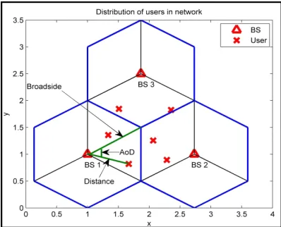
1 Distribution of users
Figure.1 shows the distribution of us-ers in a three cell configuration. Usus-ers are distributed randomly in the whole area of a virtual cell (not in the whole area of cell). The triangular shows the location of base stations, while cross illustrates the location of users. Each base station supports two users. The values in coordinate plane are given in kilometres. The radius of the cell is considered to be 1 km.
The simulation code is written in such a way that calculates the distance and angle of departure (AoD) from a base station to a user. The distance is cal-culated simply based on the coordinate plane points. The AoD is calculated relative to the broadside (boresight) of the array. If the location of the users is in the right of broadside of the array then AoD takes positive values. If the location of the users is in the left of broadside of the array then AoD takes negative value. This holds for every base station. This figure serves as a key instrument to other simulation results.
The distances and AoDs between a BS and a user for the scenario illustrated grafically above, are shown in Table 2, i.e. 0.4588 shows the distance from base station 2 to the second user of the second cell, while 28.59090 shows the AoD from base station 3 to the second user.
Uniform Linear Array (ULA) Number of Antenna Elements Nt=8 Inter'element distance d=λ/2
Angle spread 2°
Beamforming algorithm MMSE Noise power spectral density '162 dBm/Hz Path Loss L=128.1+37.6log10(d)
Shadowing 8 dB lognormal
Fading Rayleigh
Antenna Gain 15 dBi Weighting factors =1
Figure 1: A three cell configuration with two users per sector cell
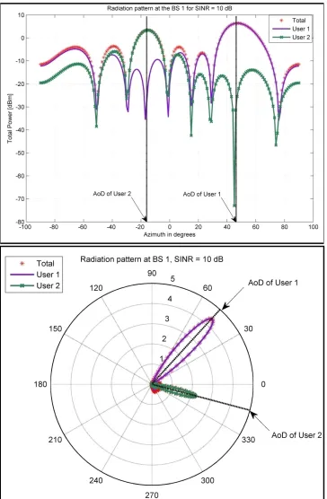
eight, and that can be seen from the number of slopes. Each of the base sta-tions supports two users, and that means that there are two main lobes per base station. Main lobe of an an-tenna radiation pattern is the lobe containing the maximum power. The figure 2 shows that the main lobes are directed to the intended users. For completeness a comparison between the data given in Table 2 and Figure.2 is given. Table 2 shows that the loca-tion of user 1 and user 2 is AoD = 45.09310 and AoD = -17.76560, respec-tively, with respect to the boresight of the array. In accordance to that, Fig-ure.2 shows that the main lobes are directed towards the user 1 and user 2, which are located exactly at the same angle given in the Table 2.
Table 2: Distances and Angle of Departures (AoDs)
from different base stations to different users
BS 1 BS 2 BS 3
Distance of user 1 (km) 0.6924 0.7153 0.8325
Distance of user 2 (km) 0.4909 0.4588 0.7453
AoD of user 1(degree) 45.0931 -8.9930 -35.9161
AoD of user 2 (degree) -16.7656 -43.3458 28.5909
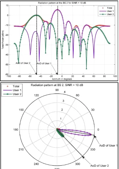
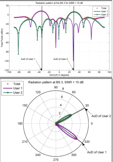
2 Power radiation pattern of different base stations
Power radiation pattern confirms the correctness of the problem formula-tion. The idea is to optimize power such that the transmitted power is concentrated only on the desired users.
The radiation pattern is given at different base stations. Moreover, this study presents the radiation pattern in two formats: rectangular and polar format. The rectangular format is illustrated in first part of each base station, while polar format in second part.
Figure.2 gives the radiation pattern of base station 1, Figure.3 the radiation pattern of base station 2 and Figure.4 the radiation pattern of base station 3.
The SINR target is considered to be 10 dB. The number of array antennas is
The second Part of Figure.2 shows that the base station needs more power to transmit the signal to user 1 than user 2. That means that the farther is user, the more power is needed to be trans-mitted for that particular user.
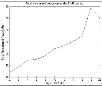
Figure 5: Total transmitted power vs. target SINR for Nt = 8 antennas, assuming 2 users
ber of the proposed algorithm is con-sidered to be 3000. This number of it-erations gives the convergence of the algorithm. The accuracy in this case is considered to be 10-1.
In both figures below it is easily to see that the total transmitted power in-creases as the target SINR inin-creases. For a SINR target of 10 dB, Figure.5 shows that the total power to be trans-mitted is 8 dBm. For the same SINR target, Figure.6 shows that the total transmitted power is 35 dBm. There-fore we have an increase in total trans-mitted power. This means that as the number of users increases, the perfor-mance of the system in terms of trans-mitted power deteriorates. This is ob-viously known because the more us-ers we have, more total power we need to transmit. Another reason is that the system used in this study is interference limited system. Another reason is that beamforming approach is limited to the number of antennas with respect to the number of users. Beamforming approach can work only on the case when the number of an-tennas in array is bigger than the num-ber of supported users. This means that the more user you have the less ability to distinguish the users in terms of beamformers, because you have limitation in the number of antennas.
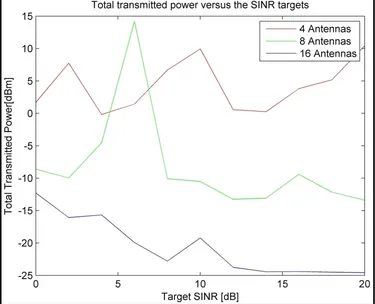
4 Effect of varying the number of an-tennas in total transmitted power
Figure.7 shows the total transmitted power vs. target SINR for K=2 user
3 Minimum total transmitted power strategy
The main idea of this study is to mini-mize the total transmitted power sub-ject to SINR targets. To solve this prob-lem an iterative algorithm is derived. Figure.5 and Figure.6 shows the simu-lation results for this analytical algo-rithm.
num-and different number of antennas Nt= 4,8,16. The figure shows that increas-ing the number of antennas improves the system performance in terms of power consumption. This is due to the fact that increasing the number of an-tennas in array the width of main beam decreases [8], which means that we need less power to transmit. With the increase of antennas, the side lobes widths also decreases, and this means that we send less power to undesired users, although the number of side lobes increases.
Because of the limitation of time to run many samples, the curves are not smooth.
5. Summary
The simulations results show the cor-rectness of the problem formulation. Power radiation pattern shows the proof of correctness. A comparison between minimise total transmitted power strategy for 2 users and 3 users shows that as the number of users in-creases, the performance of system deteriorates. This is logical consider-ing that our system model is an inter-ference-limited model. Finally a com-parison of total transmitted power between different number of antennas shows that the more number of antennas the better performance of the system.
CONCLUSION AND FURTHER WORK
Conclusion
With the demand of wireless commu-nication services and increasing popu-larity of wireless applications, the al-ready crowded wireless spectrum is getting more and more limited and expensive. To help solve this problem, many techniques are developed. One of the techniques used to increase the spectral efficiency is power optimiza-tion. This study tries to minimise the total power consumption in cellular networks while maintaining a targeted SINR.
The scenario considered in this study is a downlink MISO scenario, where base stations are coordinated across multiple cells and they consist of many antennas. In the other hand the remote users are equipped with a single an-tenna, but where many of these users may be active in each cell and are sepa-rated via spatial multiplexing using beamforming. Beamforming is the approach that minimizes the total transmitted power by directing the main lobes towards the desired users, and side lobes in the direction of un-wanted users.
The main contribution of this study is to design an iterative algorithm, find-ing the transmitted beamformers, that help minimize the total transmitted power. The algorithm is chosen to be
a correlated-based channel model, the full-correlation model. This channel model is the most accurate. The algo-rithm is based on dual uplink-down-link duality, which transforms the downlink problem in the form of up-link problem. This duality approach is solved via Lagrangian duality theory.
Further work
Although this study has answered a number of important questions re-garding optimization of transmitted power, several issues remain for pos-sible future work:
1. As an alternative to the transmit power minimization problem men-tioned in this study, one can also formulate a rate-region maximiza-tion problem subject to power con-straints at the base-stations, al-though numerical optimization of achievable rate regions are much more difficult.
2. Instead of the proposed correla-tion-based channel model, the full correlation model, other correla-tion-based channel models, such as Kronecker model, Weichselberger model or iid model, can be used.
· The current arrangement can be en-hanced to change the MISO into MIMO. MIMO channels offer greater degrees of freedom.
practice, the weights are deter-mined using an adaptive beamforming algorithm. Due to limitations of actual beamforming algorithms, errors are introduced in the beamforming weights. In this context, the performance of differ-ent beamforming algorithms can be explored with regard to their sen-sitivity to the operating channel and user conditions.
REFERENCES
A.E.Zooghby, “Smart Antenna Engi-neering”, Artech House, Jun2005
A. Wiesel, Y. C. Eldar, and S. Shamai, “Linear precoding via conic opti-mization for fixed MIMO receiv-ers,” IEEE Trans. Signal Process., vol. 54, no. 1, pp. 161–176, Jan2006
E.Visotsky and U.Madhow, “Optimal beamforming using transmit an-tenna arrays”, in Proc. IEEE Veh. Technol. Conf., vol. 1, Jul1999
F.Rashid-Farrokhi, K.J.R.Liu, and L.Tassiulas, “Transmit beamfor-ming and power control for cellu-lar wireless systems”, IEEE J. Sel. Areas Commun., vol. 16, no. 8, pp. 1437–1450, Oct1998
Hayssam Dahrouj and Wei Yu, “Co-ordinated Beamforming for the Multi-cell Multi-Antenna Wireless System”, IEEE Transactions on Wireless, May2010
M.Bengtsson and B.Ottersten, “Opti-mal downlink beamforming using semidefinite optimization”, in Proc.37th Allerton Conf. Commun. Control Comput., Sep1999
M.Schubert and H.Boche, “Solution of the multiuser downlink beamfor-ming problem with individual SINR constraints,” IEEE Trans. Veh. Technol., vol. 53, pp. 18–28, Jan2004.