TUGAS PENULISAN MAKALAH ILMIAH
MATA KULIAH
: PRASARANA TRANSPORTASI
KODE
: CEC 611
UNIT
: 3 SKS
DOSEN
: Dr. Sri Atmaja P. Rosyidi, ST., M.Sc., P.Eng.
SISTEMATIK PENULISAN TUGAS MAKALAH ILMIAH
A.
PENDAHULUAN
Tugas ini merupakan salah satu bagian dari penilaian tugas mandiri yang diberikan
kepada mahasiswa peserta kuliah Prasarana Transportasi (CEC 611) Jurusan Teknik
Sipil Universitas Muhammadiyah Yogyakarta. Tugas ini bertujuan untuk
membekali mahasiswa dalam ketrampilan menulis ilmiah dan memberikan
kepekaan mahasiswa untuk mengamati dan mengikuti isu-isu mutakhir dan
permasalahan yang dihadapi dalam perencanaan dan penyediaan transportasi
angkutan kereta api dan angkutan udara.
Makalah merupakan media penyampaian ide, gagasan, pemikiran, hasil studi, kajian
referensi dan hasil-hasil penelitian. Dengan demikian, makalah mempunyai fungsi
yang sangat signifikan bagi kalangan akademisi sebagai media untuk saling bertukar
pikiran dan
B.
ATURAN DAN PENGUMPULAN TUGAS
Tugas makalah ilmiah ini merupakan tugas individu yang harus dikerjakan selama
setengah semester perkuliahan efektif (2 bulan). Tugas ini terdiri dari penulisan
outline and makalah, dimana harus dikerjakan oleh mahasiswa pada awal
perkuliahan hingga menjelang Ujian Tengah Semester (UTS).
Makalah ini disusun megikuti beberapa tahapan yang pelaksanaannya setiap
tahapan dilakukan pada rentang minggu pertemuan kelas efektif yang dijelaskan
sebagai berikut :
Pertemuan
Kuliah Tugas Mahasiswa Keterangan
Minggu ke-1 Mencari topik dan judul untuk tugas makalah Judul makalah tidak boleh ada yang sama. Mahasiswa yang terlebih dahulu mendaftar akan mendapatkan kesempatan dalam penentuan judul makalah. Minggu ke-2 Mendaftarkan judul kepada dosen dan
memulai penulisan outline makalah. (Bagi mahasiswa yang kebetulan memiliki judul yang sama diberikan kesempatan dalam minggu ini untuk mencari topik atau judul baru lainnya).
Outline berisi urutan penulisan makalah secara sistematis. Memulai untuk mencari bahan untuk menulis outline makalah.
Minggu ke-3 Mengumpulkan outline makalah dan memulai mencari bahan untuk penulisan
untuk dilakukan perbaikan dalam penulisan makalah. Minggu ke-4 s.d.
Minggu-5
Penulisan makalah
Minggu ke-6 Mengumpulkan tugas makalah Pengumpulan dilakukan pada jam perkuliahan.
C.
SISTEMATIKA PENULISAN OUTLINE
Makalah ditulis berdasarkan susunan outline makalah berikut ini :
Bagian Pertama : ---
a.
Judul Makalah
: Judul makalah harus ditulis dengan susunan kalimat secara
ringkas dan jelas, serta mencerminkan isi makalah yang ditulis dengan baik.
b.
Penulis
: Nama penulis ditulis di bawah judul makalah secara lengkap, dan di
bawah nama penulis dituliskan status dan alamat penulis yang merupakan status
penulis dalam suatu institusi dan alamat institusi, misal : alamat universitas.
c.
Abstrak
: Abstrak berisi ringkasan makalah yang akan ditulis yang terdiri dari 3
bagian utama yaitu : pendahuluan (latar belakanG dan tujuan makalah),
metodologi (cara dan metode yang digunakan untuk mendapatkan data, kajian
literatur atau analisis suatu fenomena, yang mendasari isi dan pembahasan yang
sampaikan dalam makalah) dan hasil (komentar umum dari suatu hasil atau
kesimpulan dari sebuah review). Abstrak ditulis maksimal dalam 250 kata.
Bagian Kedua :
PENDAHULUAN
a.
Latar Belakang
: Dalam bagian ini dituliskan latar belakang yang mendasari
pemasalahan atau fenomena yang diangkat sebagai topik dan judul penulisan.
Latar belakang ini bisa berupa pernyataan yang berisi " kenapa " masalah ini
diangkat dan " apa " menjadi landasan makalah ini ditulis.
b.
Tujuan
: Bagian ini berisi tujuan dari ditulisnya makalah ini atau
studi/penelitian yang dilakukan yang mendasari ditulisnya makalah ini. Tujuan
diturunkan dari signifikasi permasalahan yang akan diselesaikan melalui studi
yang dilakukan. Pernyataan tujuan sebaiknya ditulis dalam kata kerja yang
terukur, minimal pernyataan yang dapat dituangkan dalam konsep yang jelas,
dan dituliskan dengan kalimat-kalimat yang padat dan terarah.
Bagian Ketiga :
TINJAUAN LITERATUR
atau
STUDI PUSTAKA
dan
LANDASAN TEORI
Tinjauan Literatur
atau
Studi Pustaka
: (1). Bagian ini berisi rangkuman dari studi
atau penelitian atau bentuk-bentuk kajian yang telah dilakukan oleh peneliti atau
penulis sebelumnya yang terkait dengan judul/topik makalah, atau (2). Bagian ini
dapat juga
Landasan Teori
yang berupa rangkuman teori-teori yang digunakan
untuk mendasari studi yang dilakukan yang dituliskan dalam makalah.
Bagian Keempat :
METODOLOGI PENELITIAN
terperinci mengenai langkah-langkah kerja, cara pengambilan data, cara analisis,
metode penafsiran dan presentasi hasil yang diharapkan tertuang secara lengkap
dalam naskah atau makalah publikasi. Jika makalah disajikan dalam bentuk
kerangka ide dan rangkuman kajian literatur saja maka bagian ini dapat diabaikan
dengan menggantikan bagian ini menjadi
Konsep Ide
atau
Kerangka Berfikir
dari
makalah yang disajikan.
Bagian Kelima :
HASIL PENELITIAN DAN PEMBAHASAN
Dalam bagian ini, dijelaskan secara rinci hasil kajian yang diperoleh atau
hasil-hasil studi yang didapatkan. Konsep penulisan bagian ini adalah berurutan sesuai
dengan tahapan-tahapan yang digunakan dalam pencapaian tujuan penelitian atau
studi. Untuk makalah dalam bentuk kajian literatur, maka hasil penelitian dan
pembahasan merupakan hasil kajian literatur yang disajikan atau idea yang
diusulkan atau pokok penulisan dari suatu makalah yang disampaikan.
Bagian Keenam :
KESIMPULAN
atau
PENUTUP
Pada bagian ini, penulis menyatakan suatu pernyataan singkap dan lugas, mengenai
isi makalah yang ditulisnya. Pernyataan dapat berupa jawaban dari permasalahan
yang melatarbelakangi makalah ini yang tertuang dalam bagian tujuan, yang
selanjutnya disebut sebagai Kesimpulan. Jika pernyataan yang disampaikan bersifat
umum maka bagian ini lebih sesuai disebut sebagai Penutup.
Bagian Ketujuh :
DAFTAR PUSTAKA
C
ONTOH
O
UTLINES
M
AKALAH :
IN SITU DETERMINATION OF LAYER THICKNESS AND ELASTIC MODULI OF ASPHALT PAVEMENT SYSTEMS BY SPECTRAL ANALYSIS OF SURFACE WAVES
(SASW) METHOD
1Mohd Azmi Ismail, 2Sri Atmaja P. Rosyidi, 3Abdul Rahim Samsudin 3
Abdul Ghani Rafek & 4Khairul Anuar Mohd Nayan
1Institut Penyelidikan Teknologi Nuklear Malaysia (MINT),
Bangi, 43000 Kajang, Selangor, Malaysia
Email: [email protected] 2Jurusan Teknik Sipil
Universitas Muhammadiyah Yogyakarta, Jalan Lingkar Selatan, Tamantirto, Bantul, Indonesia
Email:[email protected]
3
Pusat Pengajian Sains Sekitaran & Sumber Alam, Universiti Kebangsaan Malaysia,
43600 Bangi, Selangor, Malaysia
Email: [email protected]; [email protected] 4Jabatan Kejuruteraan Awam & Struktur,
Universiti Kebangsaan Malaysia, 43600 Bangi, Selangor, Malaysia
Email:[email protected]; [email protected]
Abstract
Spectral analysis of surface waves (SASW) is a non-destructive and in situ method for determining the stiffness profile of soil and pavement sites. The method consists of generation, measurement, and processing of dispersive elastic waves in layered systems. The test is performed on the pavement surface at strain level below 0.001%, where the elastic properties are considered independent of strain amplitude. During an SASW test, the surface of the medium under investigation is subject to an impact to generate energy at various frequencies. Two vertical acceleration transducers are set up near the impact source to detect the energy transmitted through the testing media. By recording signals in digitised form using a data acquisition system and processing them, surface wave velocities can be determined by constructing a dispersion curve. Through forward modeling, the shear wave velocities can be obtained, which can be related to the variation of stiffness with depth. This paper presents the results of two case studies for near-surface profiling of two different asphalt pavement sites.
Key words: non-destructive method, pavement, layered media, Rayleigh waves, spectral analysis, shear wave velocity, wave propagation, elastic modulus.
1. INTRODUCTION
• There are more than 60,000 kilometers of expressways and roads in Malaysia, of which more than one half are either flexible or rigid pavements.
• Most of the expressways, federal roads, state roads and council roads are more than 20 years old.
• Owing to aging roads and increasing traffic loads and volumes, the responsibility for maintenance, rehabilitation and management of pavement structures is becoming more and more critical.
• The SASW technique successfully reduces the field-testing time and improves the accuracy of the original steady-state method. It also overcomes many of the limitations of the well-known deflection-basin-based method, e.g., the falling weight deflectometer or dynaflect.
• The purpose of this paper is to describe the role of the SASW technique in assisting pavement engineers in evaluation and management of highways. The first part of the paper discusses the fundamentals of the SASW method and properties of pavement that can be detected by the method. The second section illustrates the results of the SASW tests in pavement investigations.
2. LITERATURES STUDY : Propagation of Rayleigh Waves
• The SASW is a non-destructive method for in situ evaluation of elastic moduli and layer thickness of layered systems, such as soils and pavements (Stokoe et al. 1994).
• The method is based on the phenomenon of Rayleigh wave dispersion in layered systems, i.e. the phenomenon that the velocity of propagation is frequency dependent.
• The energy of Rayleigh waves propagates mechanically from the source along the surface of a media and their amplitude decrease exponentially with depth.
• Particle motions associated with Rayleigh wave are composed of both vertical and horizontal components, which when combined, form a retrogressive ellipse close to the surface ary with frequency. However, in the layered medium where there is a variation of stiffness with depth, Rayleigh wave velocity is frequency dependent. This phenomenon is termed dispersion where Rayleigh wave refers to the variation of phase velocity as a function of wavelength.
• Rayleigh wave propagation technique may be used to determine the parameters of the elastic moduli of pavement and soil layers.
• These parameters represent the material behaviour at small shearing strain, of less than of 0.001 %.
3. RESEARCH METHODOLOGY
3.1 Field Procedure
• Elastic waves are generated (by means of impacts), on the surface of pavement and are detected by a pair or an array of receivers.
• A portable 4-channel dynamic spectrum analyser (OROS OR25 PC-Pack II) was utilized for recording and analysing the data. The common receiver midpoint (CRMP) array geometry was used (see Nazarian 1984 for detail).
• The spacing between receivers was 0.1, 0.2, 0.4, 0.8, 1.6, and 3.2 m. Piezoelectric accelerometers were used to pick up the surface wave signal.
• The accelerometers were glued to the pavement surface to ensure good coupling. The dynamic signal is generated in the pavement using a variety of impact sources depending on the frequency range of interest, which in turn influence the sampling depth.
3.2 Construction of Dispersion Curve
• When displaying the phase spectra, the analyser may not use full-scale display, instead it may display the phase in the range of ±180º and hence cause it to wrap.
• The step to find the actual phase of a frequency is to count the number of full 360º cycles preceding the frequency and to add that to the fraction of the last cycle or the frequency. The process is called unwrapping of the phase (Nazarian 1984).
• Data points that did not satisfy the following two criteria were discarded: (i) a coherence magnitude of 0.95, and (ii) a wavelength greater than ½D and less than 3D (Heisey et al. 1982). This operation is called ‘masking’.
• It should be noted that velocities obtained from an experimental dispersion curve are not the actual Rayleigh wave velocities, but rather apparent or phase velocities. The existence of layers with higher or lower velocities at the surface of a medium, such as a pavement structure, affects the measurement of the velocities of the underlying layers.
3.3 Inversion of Dispersion Curve
• The process of converting the dispersion curve into the shear wave velocity profile is called inversion or forward modeling.
• Data points of the experimental dispersion curve are usually compressed into a smaller number of data points by averaging a certain range of experimental data points into one data point.
• There are basically two inversion processes, a simple and a refined one.
4. RESULT AND DISCUSSION
CASE STUDY 1: LANDED-ZONE 4-B, PRECINT 11, PUTRAJAYA
• The SASW testing was carried out on a pavement surface at Landed-Zone 4-B, Precint 11, Putrajaya construction project (SASW array PREC11-JP1).
• The pavement profile consists of an asphalt layer (100 mm thick), a base of crushed aggregates (300 mm thick), and a sub base of sand (200 mm thick) over a metasediment sub grade.
• Material properties and thickness of the four layers are shown in Figure 6(a). In this study, the receiver spacing of 10, 20, 40, 80, 160 and 320 cm were used.
• The modulus and depths determined by the SASW measurements from the inversion are in good agreement with each layer of the pavement profile. A zone with higher modulus is interpreted from 0 to 10 cm for the asphalt concrete surface layer that has the highest stiffness properties (100 – 1000 MPa). An abrupt decrease of the modulus then occurs at the transition layer of the base followed by a gradual increase of the modulus for the sub base and sub grade with elastic modulus of around 10 MPa.
CASE STUDY 2: KM 296, NORTH – SOUTH EXPRESSWAY
• the SASW testing was carried out on a pavement surface at Km 296 (North Bound), Seremban – Bangi section of the North – South Expressway (SASW array LRSB-ApJ) during rehabilitation works. The pavement structure consists of an asphalt layer (180 - 200 mm thick), a sub base of crushed aggregates and fine sand (2000 - 2500 mm thick), over a metasediment sub grade.
• The sources for the Rayleigh wave employed were slightly different from those in the case study 1. For high frequency signals, 2-inch nail and small hammers were used, while geological hammer was used for receiver spacing higher than 100 cm.
• The profiles determined by the SASW measurements show good agreement with the pavement profile. A zone with higher modulus is interpreted from 0 to 20 cm for the asphalt concrete surface layer that has the highest stiffness properties (100 – 1500 MPa). This surface layer is slightly stiffer than the PREC11-JP1 site as a more stringent specification was applied to the former. Similarly, an abrupt decrease of the modulus occurs at the transition layer of the sub base followed by a gradual increase of the modulus for the sub grade.
5. CONCLUDING REMARKS
• Samples of the asphalt pavement structure for laboratory analysis were not available during the study. The thickness of layering obtained from the inversion analysis compared well with the existing profile obtained from the construction record.
Table 1 Comparison of shear wave velocity from this study to that of Nazarian (1984) and Al-Hunaidi (1998).
Shear wave velocity (m/s) Profile
This study Nazarian (1984)
Al Hunaidi (1998)
Surface course 900 – 2000 2425 1000 – 2500
Sub base course 195 – 270 301.95 100 – 500
Sub grade 200 – 400 271.45 80 – 300
• The SASW method has managed to characterise all the layers of the pavement profile in terms of shear wave velocity and dynamic shear and elastic modulus satisfactory. The method can be applied in the early stages of pavement evaluation for detecting the dynamic properties and thickness of the profile.
6. REFERENCES
Al-Hunaidi, M.O. 1998. Evaluation-based genetic algorithms for analysis of non-destructive surface waves test on pavements, NDT &E International, Vol.31, No.4, pp.273-280.
Ganji, V., Gucunski, N & Nazarian, S. 1998. Automated Inversion Procedure For Spectral Analysis of Surface Wave. Journal of Geotechnical and Geoenvironmental Engineering, August 1998, pp.757-770.
Haskell, N.A. 1953. The Dispersion of surface waves in multi-layered media. Bull. Seismol. Soc. Am., Vol. 43, No. 1, pp 17-34.
Hossain, M.M. & Drnevich, V.P., 1989. Numerical and optimisation techniques applied to surface waves for back-calculation of layer moduli. In Non-destructive testing of pavements and back-calculation of moduli. Edited by Bush, A.J., III & Baladi, G.Y. American Society for Testing and Materials, Special Technical Publication 1026, pp. 649-669.
Nazarian, S., 1984. In-situ determination of elastic moduli of soil deposits and pavement systems by Spectral-Analysis-Of-Surface-Wave Method. Ph.D. Dissertation, University of Texas at Austin, 452 pp.
Nazarian, S. & Stokoe II, K. H. 1984. In-situ shear wave velocity from spectral analysis of surface waves. Proc. 8thWorld Conf. On Earthquake Engineering, 3, pp 31-38.
Richart, F.E.Jr., Hall, J.R., Jr. & Woods, R.D. 1970. Vibrations of soils and foundations. New Jersey: Prentice-Hall.
Sayyedsadr, M. & Drnevich, V.P. 1989. SASWOPR: A program to operate on spectral analysis of surface wave data. In Non-destructive testing of pavements and back-calculation of moduli. Edited by A.J. Bush III & G.Y. Baladi. American Society for Testing and Materials, Special Technical Publication 1026, pp 670-682
Stokoe II, K.H., Wright, S.G., Bay, J.A. & Röesset, J.M., 1994. Characterization of geotechnical sites by SASW method. Geotechnical characterization of sites, R.D. Wood (Ed), Oxford and IBH Publishing Co., New Delhi, India, 15-26.
C
ONTOH
M
AKALAH
S
TUDI
L
ITERATUR :
CIVIL ENGINEERING APPLICATIONS OF THE SPECTRAL
ANALYSIS OF SURFACE WAVE (SASW) METHOD
Khairul Anuar Mohd. Nayan, Sri Atmaja Rosyidi, Mohd. Raihan Taha &
Mohd.Azmi Ismail
Depart.of Civil & Structural Eng., Universiti Kebangsaan Malaysia, Malaysia
Depart. Of Civil Eng., Universitas Muhammadiyah Yogyakarta
ABSTRACT
Civil engineering works covers a wide spectrum of applications that include projects that are small and huge in scale. The applications from a single wave form have never been so successful and widely applied in Civil engineering as the Spectral Analysis of Surface Wave. Its ability to define depths and dynamics of materials properties in both profiling and imaging has been rapidly utilized to address engineering structures of a few millimetres of depths to bedrock as deep as 50 meters has been widely reported. The direct involvement of civil engineers themselves in this method of geophysical test has been more intensive than the other geophysical method. Their applications include various layers of pavement evaluations, concrete testings, landfills and various applications in geotechnical evaluations and design. SASW is more practical in the field as the source is reasonably simple as compared to the other geophysical methods. In this paper the various methods of the SASW applications in civil engineering are highlighted so that geophysicist are able to appreciates the needs and accuracies that are required by civil engineers.
1. INTRODUCTION
The SASW method is based on the analysis of the dispersive characteristic of surface waves in a non-homogeneous medium. The method is a non-destructive test in which both the source and the receivers are located on the ground surface. No requirement for expensive boreholes, repeatability of the test, and a simple set-up and test procedure are among the advantages of this technique.
The surface waves have been utilized by researchers in a number of applications. In geotechnical engineering, for instance, the use of surface waves is not new. Geotechnical engineers like Terzaghi (1943) and Hvorslev (1949) were among the pioneers of the surface wave geophysics. Jones (1958), on the other hand, used surface wave to assess materials under road pavements but his work was unsuccessful because of the insensitive recorders and signal receivers being used at that time. With the advent of spectral analysis and the computer technology, the traditional Rayleigh wave method based on the steady state method has been revolutionised to the SASW method. This method was developed by changing the source to the impact hammer position until the appropriate frequency for the field measurement was obtained (Heisey 1982, William 1981). Latter it was improved to the spectral analysis of surface wave (SASW) method with the generation of the dispersion curve with the factors affecting the calculation of the elastic moduli, thicknesses of pavement and soil profile were studied (Nazarian & Stokoe 1984).
The stress strain behaviour of cyclically loaded soils is complex and geotechnical engineers are challenged by the need to characterize this behaviour with accurate and simple models. The balance between accuracy and simplicity depends on many factors and several combinations have been proposed. For geophysical methods that induce low-strain (<10-3 %) the soil models are based on equivalent linear model. These models are the simplest and most commonly used in dynamics, but they have a limited ability to represent many aspects of soil behaviour under cyclic loading conditions. Most seismic geophysical methods or tests induce shear strains lower that 10-4 % and the shear wave velocity (Vs) can be used to compute the Gmax using the expression Gmax = ρ × Vs2, where ρ is the mass
density of the soil. The measured shear wave velocity is generally considered the most reliable means to obtain the Gmax for a soil deposit. Therefore, the maximum shear modulus is developed at low shear
strain where geophysical tests are used. If the strain increases the secant shear modulus will decrease where this shear modulus degradation with cyclic strain is by means of the modulus reduction curve. The modulus reduction curve normalizes the shear modulus (G) with respect of the maximum shear modulus (Gmax) and is commonly referred to as the modulus ratio. Figure 1 shows a schematic of the
typical cyclic behaviour of soils.
Figure1 Stress-strain curve with variation of shear modulus and modulus reduction curve
Shear wave velocity (Vs) is the most commonly used measured parameter used in shallow soil geophysics for soil characterization. It is used to calculate the following parameters in the elastic range of soil behaviour. The importance in its utility is that the particle of motion travels perpendicular to the direction of wave propagation being able to measure the shear properties of the soil skeleton and not the fluids that cannot take shear.
Shear Modulus (G) is a calculated parameter based on the Vs using the simple elastic relationship Gmax
= ρ × Vs2 . The mass density is often estimated or measured by a nearby subsurface sampling or using correlations. Advanced correlations to estimate the value of the dynamic shear modulus are available based on the standard penetration test, Atterberg Limits (plasticity index) and grain size distributions (Vucetic & Dobry 1991, Idriss et al. 1980). The shear modulus is used to perform more advanced soil modelling, and dynamic response of the soil-structure interactions. Shear modulus at low strain levels as measured by geophysical techniques will provide the elastic parameter for machine foundation analysis or earthquake engineering. The important utility of this parameter is that it can be used as a varying parameter with respect to strain making the soil response represents the real modulus degradation in soil behaviour. This parameter is used in defining the stiffness matrices for finite element analysis of earth structures and foundation soils.
Maximum Shear Modulus (Gmax) is used to normalize the shear modulus (G) vs. shear strain
relationships. These normalized relationships allow the engineer to use well-established degradation curves and scale them to the measured in-situ value of Gmax. For example, the classic relationships of
the shear moduli for cohesionless and cohesive soils are provided in Seed et al. (1984) and Sun et al. (1988). In the absence of extensive dynamic soil testing at all ranges of shear strain these curves are used and Gmax is used as the scaling parameter.
relationships for cohesionless and cohesive soils are provided in Seed et al. (1984) and Sun et al. (1988). Since damping ratio is also shear strain dependent, it is required to have several values with strain. Dynamic analysis results are also influenced by the damping ratio for single and multi degree modal systems. The effects of soil-structure interaction also influence the damping of the system making it an area where recent research has focused. The utility of this parameter is based on the ability of the system to absorb dynamic energy and how this will affect the duration and modes of vibration.
The SASW method is based on the particles motion of Rayleigh wave in heterogeneous media. The energy of Rayleigh waves from the source propagate mechanically along the surface of media and their amplitude decrease rapidly with depth. Particle motions associated with Rayleigh wave are composed of both vertical and horizontal components, which when combined, formed a retrogressive ellipse close to the surface. In homogenous, isotropic, elastic half-space, Rayleigh wave velocity does not vary with frequency. However, Rayleigh wave velocity varies with frequency in the layered medium where there is a variation of stiffness with depth. This phenomenon is termed dispersion where the frequency is dependent with the Rayleigh wave velocity. The ability for detecting and evaluating of the depth of the medium is influenced by the wavelength and the frequency generated. The shorter wavelength of higher frequency penetrates the shallow zone of the near surface and the longer wavelength of lower frequency penetrates deeper into the medium.
To derive a theoretical dispersion of Rayleigh motions, the mathematical formulation of wave propagation in layered system was generated. There are several modeling approaches available for SASW applications. Among them are: (1) the transfer matrix method (Thomson 1950 & Haskell 1953); the dynamic stiffness matrix method (Kausel & Röesset 1981) and the finite difference method (Hossain & Drnevich 1989). The transfer and stiffness matrix methods provide exact formulation as compared to the other methods (Ganji et al 1998). Although the approach of the inversion methods can be different, however, all the methods assume that the profile consists of a set of homogeneous layers extending to infinity in the horizontal direction. The last layer is usually considered as a homogeneous half-space.
3 METHODOLOGY
3.1 Steady-State Surface Wave Method
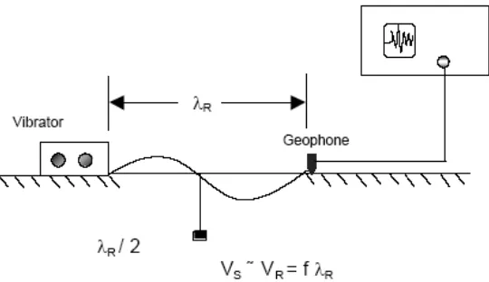
The steady state surface wave technique does not require boreholes and is another in-situ method used to measure the shear modulus (G) of all types of soils. In this test, an electromagnetic oscillator at high frequency (30 to 1000 cycles/second, cps) or a rotating mass type oscillator to produce low frequency vibrations (less than 30 cps) are used. These surface vibrators generate Rayleigh R-waves, which at low strains have nearly the same velocity as the shear waves. The ground surface can be deformed as shown in Figure 2. The shear wave velocity is computed from the Rayleigh wave-length measured with receivers placed along the ground surface, and the frequency of vibration at the source using the following equation (Gazetas, 1991):
VS ~ VR = f λR (1)
Figure 2 Steady-State Surface Wave Test
The effective depth of the R-wave has been empirically related to the soil layer at a depth equal to one half the wavelength, λR (Heukelom and Foster 1960). The variation of shear wave velocity with depth
is obtained by changing the frequency of the source and thus changing the wave-length λR. This
technique requires however, large force-generating equipment that can operate at low frequencies (i.e., rotating mass oscillators) to explore deep soil profiles.
3.2 Spectral Analysis of Surface Wave
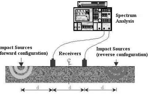
The SASW method evolved from the steady-state vibration test discussed in the previous section. The purpose of the SASW test is to determine a detailed shear wave velocity profile working entirely from the ground surface. The method involves using a series of successively longer source-receiver arrays to measure the propagation of Rayleigh waves over a wide range in wavelengths. A vertical impact is applied at the ground surface generating transient Rayleigh waves. The sources used in SASW measurements include solenoid-operated impactors, hammer and V-meters (high frequency sources) and large drop weights and bulldozers (low-frequency sources).Two or more receivers placed at the surface, at known distances a part monitor the passage of these waves (Stokoe et. al. 1994; Gazetas 1991). Several sets of test with different receivers spacing are required to sample different depths. Shot receiver spacing with high frequencies (short wavelength) are used to sample shallow layers while long receiver spacing with low frequencies (long wavelengths) are used in sampling deeper layers. Figure 3 shows a schematic of the field setup of this test. The receivers or vibration transducers produce signals that are digitized and recorded by a dynamic signal analyzer, and each recorded time signal is transformed to the frequency domain using a fast Fourier transform algorithm.
The phase difference (φ(f)) between two signals is then determined for each frequency, and the travel time (t(f)) between receivers is obtained for each frequency as follows:
t(f) = φ(f) / 2πf (2)
where, f(f) = phase difference for a given frequency in radians and f = frequency in cycles per seconds (cps). The velocity of R-waves is determined as:
VR = Δd / t(f) = λR f (3)
Figure 3 Spectral Analysis of Surface Wave
The calculations of VR and λR are performed for each applied frequency, and the results plotted in the
form of a dispersion curve. The dispersion curve is the characteristic or “signature” of a site. Using forward modeling or “inversion” analysis, the dispersion curves are used to determine the shear wave velocity profile of the site. Forward modeling is an iterative process involving assumption of a velocity profile and a theoretical dispersion curve for a given site using the two-dimensional solution for waves propagating along the surface of an elastic medium. The theoretical dispersion curve is then compared to the experimental curve measured at the site. The assumed profile is then modified and the process repeated until a match is achieved between theoretical and experimental dispersion curves. Shear moduli and shear wave velocity of the soil profile are then determined (Stokoe, et. al., 1994). It is to note that, in a deep, homogeneous subsoil profile where the subsurface can be represented by a half-space, the signals of the transducers would have the same shape. However, in a layered soil profile, the various frequency components generated by the source propagate at different speeds, thus arriving at different times at the two receiver locations, and the signals would then have different shapes (Gazetas 1991).
4 APPLICATIONS
4.1 Soil Profile
The study of the SASW method on the soil profile was pioneered by Heisey (1982) and Nazarian & Stokoe (1984) where layered soil profile and their corresponding stiffness were accurately determined. Svensson & Möller (2001) also compared the dynamic shear modulus from the SASW method and the Seismic Cone Penetration Test (SCPT) and were found to be in good agreement. Matthews et al (1996) had shown that the SASW was able to measure stiffness at small strain level of less than 0.001 % where values of the small strain stiffness are required to predict ground deformation under dynamic loading. The comparison between laboratory measurement of the resonant column and the SASW for residual soil profile was also tested by James et al (1999). The result shows that both testings were found to be in good agreement.
4.2. Pavement Profile
calculated based on the deflection. In Malaysia, Rosyidi et al. (2002) implemented the SASW measurement on the new constructed road at Putrajaya. From their study, the comparison between thickness of pavement layer from the SASW result and the road profile was found to be in good agreement.
4.3. Liquefaction potential
The use of Vs as an index of liquefaction potential is justified since both Vs and liquefaction potential are influenced by many of the same factors (e.g. void ratio, effective confining pressure, stress history and geologic age). The study of liquefaction using the SASW method was successfully demonstrated Stokoe & Nazarian (1983). Their result had shown the shear wave velocities of the liquefiable layer were less than 450 fps. Andrus et al (1998) measured the liquefaction potential in the improved and unimproved soil area at Treasure Island, California where were used the two procedures with the following equation:
(4)
(5)
where, τ is cyclic shear stress resisting liquefaction, amax is peak horizontal ground surface acceleration,
σ’v is initial effective stress, g is acceleration of gravity and Vs is shear wave velocity. From their
result had shown that two liquefaction assessment procedures based on Vs correctly predicted no
liquefaction fro the improved area and marginal liquefaction for the unimproved area. This study further could support the usefulness in situ Vs for predicting liquefaction potential and demonstrated the potential of SASW method for rapid delineation of weak layers.
4.4. Attenuation properties for earthquake evaluation
The attenuation property is an important parameter to evaluate the vibration propagation in the material affected by earthquake. The SASW method can simultaneously measure the dispersion of motion and attenuation curves from the surface of the ground. Rix et al (2001) demonstrated the technique for obtaining attenuation using SASW. From their result, the material attenuation was easily obtained from the displacement transfer function.
4.5. Control of fill materials
Ismail et al (2002) conducted the SASW testing on compacted fill at Block A, College H, UKM, Malaysia. The result showed that the SASW was able to determine the depth of the fill material at the site. Moxhay et al (2000) also demonstrated the potential use of the SASW method for the monitoring of soil stiffness. Their result shows that the range of surface wave testing is a viable and economic technique for effectively monitoring ground improvement work. Their results had shown that the method can be applied to both cohesive as well as granular soils. Kim et al (2001) carried out the SASW test to evaluate the density in compaction works. Their study has proposed the combined method of SASW and Free-Free Resonant Column test to evaluate the in situ density of compacted soil layer with following equation:
Vs = 15.9 ×γd – 139.2 (6)
where, the unit of Vs and γd were m/sec and kN/m3. The field verification study performed at
Hoengsung road construction site in Korea had shown the great potential of applying the proposed method.
4.6. Structural evaluation of concrete
dispersive characteristics of multi-layer cement mortar system with a finite thickness. Using forward modelling, the shear wave velocity of each layer in the multi-layer system can be obtained and the material properties of each layer can then derived using the shear wave velocity result. From their study the SASW method can be utilized in examining the structural elements of the general concrete the structural structures.
4.7. Obstacle detection method
Gucunski et al (2000) implemented this method in the field for detection of a cavity under a highway. The result had presented the potential of SASW technique in detection of cavities and other anomalies under roads and highways in a karts terrain. The SASW was implemented on the section of interstate expressway I-80 in the New Jersey. The result showed the significant fluctuations in the dispersion curve were clearly observed where represented as the cavities in the road material.
4.8. Offshore method
Rosenblad (2000) developed the SASW methodology for implementing in the underwater environment. Each sets of SASW tests performed in his study yielded insight into various approaches of effectively implementing the SASW method offshore. The result from testing offshore Vancouver demonstrated that small explosives can be used effectively as a source for SASW underwater. The results from the tests in 40 ft of water demonstrated that the traditional SASW methodology applied at this location yielded a consistent and interpretable dispersion curve. From the tests performed along the Galveston shoreline had shown that the application of the SASW methodology for saturated soil conditions is suited to the underwater environment.
5 CONCLUSIONS
The SASW method is a seismic technique employing Rayleigh waves to determine in situ shear waves velocity profiles. This method is a valuable tool to characterizing the materials and is very useful for many civil engineering applications.
6 REFERENCE
1. Al-Hunaidi, M.O., 1998, Evaluation-based genetic alogarithms for analysis of non-destructive surface waves test on pavements, NDT&E international, Vol.31,No.4, pp.273-280
2. Andrus, R.D., Chung, R.M., Stokoe, K.H.II & Bay, J.A. 1998. Delineation of densified sand at Treasure Island by SASW testing. Geotechnical Site Characterization. Balkerna. Rotterdam 3. Cho, Y.S. and Lin, F-B, 2001, Spectral analysis of surface wave response of multi-layer thin cement
mortar slab structure with finite element thickness, ND&T E International 34 (2001),Elsevier Science,pp.115-122
4. Ganji, V., Gucunski, and Nazarian, S. 1998. Automated Inversion Procedure For Spectral Analysis of Surface Wave. Journal of Geotechnical and Geoenvironmental Engineering, August 1998, pp.757-770.
5. Gazetas, G., 1991, Foundation Vibrations: Foundation Engineering Handbook, 2nd Edition, Hsai-Yang Fang, and Editor, 553-593.
6. Gucunski,N., 2000, Field Implementation of Surface Waves for Obstacle Detection (SWOD) Method, Roma 2000, 15th WCNDT.
7. Heukelom, W. & Foster, C.R. 1960. Dynamic testing of pavements. Journal of Soil Mechanic and Foundation Division. Proc. ASCE 86 (SM1 Part 1).
8. Haskell, N.A. 1953. The Dispersion of surface waves in multilayered media. Bull. Seismol. Soc. Am., Vol. 43, No. 1, pp 17-34.
9. Hossain, M.M., and Drnevich, V.P., 1989. Numerical and optimisation techniques applied to surface waves for back-calculation of layer moduli. In Nondestructive testing of pavements dan back-calculation of moduli. Edited by Bush, A.J., III, dan Baladi, G.Y. American Society for Testing dan Materials, Special Technical Publication 1026, pp. 649-669.
11.Heisey, J.S., 1982, Determination of In Situ Shear Wave Velocity from Spectral Analysis of Surface Wave, Master Thesis, University of Texas, Austin, pp.300.
12.Idriss, I.M., Dobry, R., & Singh, R.D. 1978. Nonlinear behavior of soft clays during cyclic loading, Journal of the Geotechnical Engineering Division, ASCE, 104(GT12), 1427-1227.
13.Ismail, M.A., Samsudin, A.R., Nayan, K.A.M. & Rafek, A.G. 2002. Use of the Spectral-Analysis-of-Surface-Wave (SASW) Method in Engineering Geology Study. Geological Society of Malaysia Annual Geological Conference 2002. May 26-27, Kota Bharu. Malaysia. pp.329-334.
14.James, A.S., Hoyos, L.Jr., Mayne, P.W., Macari, E.J. & Rix, G.J. 1999. Field and laboratory measurements of dynamic shear modulus of Piedmont residual soils. ASCE Geotechnical Special Publication, 92, pp.12-25.
15.Luna, R. and H. Jadi, 2000. Determination of Dynamic Soil Properties Using Geophysical Methods," Proceedings of the First International Conference on the Application of Geophysical and NDT Methodologies to Transportation Facilities and Infrastructure, St. Louis, MO, December 2000. 16.Joh, S.-H., 1996. Advances in data interpretation technique for Spectral Analysis-of-Surface-Waves (SASW) measurements. Ph.D. Dissertation, the University of Texas at Austin, Austin, Texas, U.S.A., 240 pp.
17.Kausel, E., and Röesset, J.M., 1981. Stiffness matrices for layered soils. Bull. Seismol. Soc. Am., 72, pp 1743-1761.
18.Kim, D.S, Shin M.K and Park H.C., 2001, Evaluation of density in layer compaction using SASW method, Soil Dynamic and Earthquake Engineering 21 (2001), Elsevier Science, pp.39-46.
19.Madshus, C., and Westerdahl, H., 1990. Surface wave measurements for construction control and maintenance planning of roads and airfields. Proc. 3rd. Int. Conf. On Bearing Capacity of Roads and Airfields, July 3-5, Trondheim, Norway.
20.Matthews, M.C., Hope, V.S. and Clayton, R.I., 1996. The geotechnical value of ground stiffness determined using seismic methods. In Proc. 30th Annual Conf. of the Eng. Group of the Geol. Soc., University of Lige, Belgium.
21.Moxhay, A.L., Tinsley, R.D. & Sutton, J.A. 2000. Monitoring of soil stiffness during ground improvement using seismic surface waves. Geotechnical Engineers, GDS Instrument Limited. 22.Nazarian, S., 1984. In-situ determination of elastic moduli of soil deposits and pavement systems by
Spectral-Analysis-Of-Surface-Wave Method. Ph.D. Dissertation, University of Texas at Austin, 452 pp.
23.Nazarian, S. and Stokoe II, K. H. 1984. In-situ shear wave velocity from spectral analysis of surface waves. Proc. 8thWorld Conf. On Earthquake Engineering, 3, pp 31-38.
24.Rix, G.J. 1988. Experimental Study of Factors Affecting the Spectral Analysis of Surface Waves Methods. PhD dissertation. The University of Texas at Austin.
25.Rix, G.J., Bay, J.A, and Stokoe II, K.H., 1990. Assessing in situ stiffness of curing Portland cement concrete with seismic tests. Paper presented to Annual Meeting, Transportation Research Board, Washington, D.C., January.
26.Rix, G.J., Lai, C.G. & Foti, S. 2001. Simultaneous measurement of surface wave dispersion and attenuation curves. Geotechnical Testing Journal. Vol.24.No.4. pp.350-358.
27.Rosenblad, B.L. 2000. Experimental and theoretical studies in support of implementing the spectral-analysis-of-surface-waves (SASW) method offshore. Disertasi PhD. The University of Texas at Austin.
28.Rosyidi, S.A., Nayan, K.A.M., Taha, M.R. & Mustafa, M.M. 2002. The measurement of the dynamic properties of flexible pavement using Spectral-Analysis-of-Surface-Wave (SASW) Method. The Symposium of Inter-University Transportation Studies Forum. University of Indonesia. Jakarta.
29.Röesset, J.M. Chang, D.-W., Stokoe, K.H. II & Aouad, M. 1990. Modulus and thickness of the pavement surface layer from SASW test. Transportation Research Record 1260,pp. 53-63.
30.Röesset, J.M. Chang, D.-W. & Stokoe II, K.H. 1991. Comparison of 2-D and 3-D models for analysis of surface wave tests. Proc. of the 5th International Conference on Soil Dynamics and Earthquake Engineering: 111-126.
31.Sanchez-Salinero, I. 1987. Analytical Investigation of Seismic Methods Use for Engineering Applications. PhD dissertation. The University of Texas at Austin.
32.Seed, H.B., Wong, R.T., Idriss, E.M., & Tokimatsu, K. 1984. Moduli and Damping Factors for Dynamic Analyses of Cohesionless Soils, Report No. UCB/EERC-84/11, Earthquake Engineering Research Center, University of California, Berkeley.
34.Sheu, J.C. 1987. Application and Limitations of the Spectral Analysis of Surface Waves Method. PhD dissertation. The University of Texas at Austin.
35.Stokoe, K.H. II & Nazarian, S. 1985. Use of Rayleigh Waves in Liquefaction Studies. Measurement and use of shear wave velocity for evaluating dynamic soil properties. Proc. Of a Geotechnical Eng. Div. Session at ASCE Convention, Dever, Colorado, May 1, pp. 1-17.
36.Stokoe, K.H. II, Wright, S.G., Bay, J.A, and Roesset, J.M., 1994. Characterization of geotechnical sites by SASW method. Geotechnical characterization of sites, R.D. Wood, ed., Oxford and IBH Publishing Co., New Delhi, India, pp. 15-26.
37.Sun, J.I., Golesorkhi, R., and Seed, H.B., 1988, Dynamic Moduli and Damping Ratio for Cohesive Soils, Report No. UCB/EERC-88/15, Earthquake Engineering Research Center, University of California, Berkeley.
38.Svensson, M. & Möller, B. 2001. Geophysics in soil mechanics-in situ shear moduli determined by SASW-technique and more traditional geotechnical methods. Swedish geotechnical Institute. Linköping. 40 pp.
39.Tawfiq, K., Subanjo, J. & Armaghani J. 2000. Curvilinear behavior of base layer moduli from deflection and seismic methods. Transportation Research Record 1716 : 55-63.
40.Thomson, W.T. 1950. Transmission of elastic waves through a stratified solid medium. Jour. of Appl. Phys., Vol. 21, Feb. 1950, pp 89-93.
41.Vucetic, M. & Dobry, R. 1991. Effect of Soil Plasticity on Cyclic Response, Journal of Geotechnical Engineering, 117(1), 89-107.
42.William,O. 1981, Rayleigh wave velocity measurement using broad band frequency sources, Miscellaneous Paper EL-81-3, US Army Engineer Waterways Experiement Station, Vicksburg. 43.Yoder, E.J. and Witczak, M.W, 1975, Principle of pavement design, John Willey & Sons, New
York.
44.Zagyapan, M. and Fairfield, C.A., 2002, Continuous surface wave and impact methods of measuring the stiffness and density of railway ballast, NDT&E International 35 (2002), Elsevier Science,pp.75-81
6. ABOUT AUTHORS
Khairul Anuar Mohd. Nayan is a lecturer at Dept. of Civil & Structural Eng. Universiti Kebangsaan Malaysia. He received the B.Sc. from Bristol University, UK and the Master of Science in Geotechnic from UKM. His research interest correlates with geotechnic, site investigation and non destructive testing.
Sri Atmaja Rosyidi is a lecturer at Dept. of Civil Eng., Muhammadiyah University of Yogyakarta (MUY), Indonesia. He holds the Sarjana Teknik degree from UMY and Certificate of Engineer (C.Eng) from the Ministry of Public Works, Indonesia. He received the Master of Science and PhD degree from UKM.
Mohd.Raihan Taha is an Professor in Geotechnic and Geoenvironment at Dept. of Civil & Structural Eng. Universiti Kebangsaan Malaysia. He received the Ph.D degree from the Louisiana State University, US.