Abstract— Digital image processing is a rapidly growing technology with many applications in the fields of science and technology. One of common application is the system control of a navigation mobile robot either to detect the object barrier, to control the motion of a mobile robot or to control the movement of the motion that has been made with the help of computers. In the process, the final project of digital image system was implemented to capture object pixels from the camera to the captured object, and then compared with the distance of the point to the computer program using Visual C # object 2010. The Parameter used in the detection process is the object color. Whereas the object's position and height were used as an input camera for linear and angular velocities to set how large the pixels have been captured. By using OpenCVand image processing with webcam feature, the program can be started by writing the commands. The process of image processing is used to detect objects, so that the data obtained from this process will be about the midpoint of the object and the extents of the detected object. The data obtained was used as an approach to track the trajectory of the object. The success of this Open Source Computer Vision (Open CV) was determined by the accuracy of performing image and the given knowledge base learning. The test results showed that the camera catches the navigated robot and see the things that are in the arena.
Keywords— E-learning Image processing, Open CV, Robot motion, State-Chart
I. INTRODUCTION
TILIZATION of the internet is not only for distance learning education, but also for development of conventional education system. E-learning is a learning model that is created in digital format through electronic devices and aims for expanding the access learning systems to public education. The essence of e-learning is actually a virtual learning via internet access and electronic media, namely computer [1, 2]. Distance learning that utilizes
Rossi Passarella is head of Lab. Industrial Automation, and lecturer from.Department of Computer Engineering Faculty of Computer Science. University of Sriwijaya. Indonesia (e-mail:[email protected]).
Astri Agustinaand Junkani is a student from Department of Computer
Engineering Faculty of Computer Science. University of Sriwijaya. Indonesia
Sutarno is with Lab. Industrial Automation, and lecturer from Department
of Computer Engineering Faculty of Computer Science. University of Sriwijaya. Indonesia (e-mail: [email protected]).
Kemahyanto Exaudi was a staff from faculty of computer science,
computer technology enables learners to learn through computers in their respective places without having to physically appear to follow the lessons / lectures in a class. In this system, e-learning will be discussed among the children by setting up the desired line and assisted with robots.
There are three main aspects in the development of robotic study such as the mechanism of motion, electrical circuits’ i.e; sensors and actuators, and the program that controls the working robot. In special cases, working robot is an activity with a specific algorithm to be mapped in a program. One of such cases is the activity that involves the completion of robot motion equipped with webcam features as e-learning media.
This robot act as a device with motion base on the input colors which captured by the webcam. Many researches have been conducted to determine the motion of the robot with a various methods [3-9], one of them is the state-chart method. This method shows a various state of momentary which are traversed by the object, as well as events caused by transition of one state to another, and the activity as a result from change of state [10].
In this study, the authors used image processing technology to determine the pixel size of the arena and state-chart method. This method uses webcam as the image capture so that it is more efficient in determining the object point.
II.METHOD
The methods are divided into two categories, namely:
A. Thinking
In this category, when the robot is outside the lines which indicate by the reading of both left and right variables at 0, so that the robot moves to correct direction, the robot must receive the input from the camera. The robot movement has to be aware of its own existence or position whether it is on the correct track or not. When the robot realizes its position, the control can be done easily. An example of the correct logic robot is when the robot is in the middle of the line, it will move straight forward, while when the robot is on the left side of the line, then it will move to the right side. But, when the robot is on the left side of the line and the line suddenly disappears, the robot will turn sharply to the right and so on.
Design Concept of State-Chart Method
Application through Robot Motion Equipped
With Webcam Features as E-Learning
Media for Children
Rossi Passarella, Astri Agustina, Sutarno, Kemahyanto Exaudi, and Junkani
B. Drawing (and Thinking)
The possible positions of the robot (state) can be drawn in the form of a box with slightly rounded ends (or may be drawn as spheres). Transition from one state to another is described as an arrow and the causes of the transition condition are written above the arrow, while controlling the robot activities itself missal, can be written in the state (circles).
Fig 1. Shows the complete representation of the control logic in the form of State-chart robot which used in this study. It may previously unknown State-chart, but the diagram in Fig 1 seems to be very intuitive and easy to understand, so it will be easy to understand what is desired by those images.
Fig. 1 State-chart diagram
III. RESULTS AND DISCUSSION
A. Physical robot model
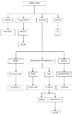
Designing a physical model of mobile robots is part of engineering art [11-13] since to make the prototype, engineer need the creation of interactive, kinetic and behavior-based art of the robot, to help the engineer in designing process, the tree diagram of material selection is applied to determine the need of mobile robot (fig 2). This tree diagram is to break down the system into the small part so it will help in decision to choice the material, sensor, actuator, energy source, program software and method.
Making robot mechanics from its base components is a difficult job. One of the greatest difficulties is designing the propulsion system, for indoor robots nearly always consist of electric motors. Designing an electric drive system requires knowledge in choosing a correct motor for the size and weight of the robot, the motor can contain a built in gearbox.
The robot made in two-storey, where the form below with a width of 150 mm as it used to place motor driver, batteries, and DC motor with gearbox. At levels above, it's used for placing microcontroller and radio transmitter. The arrangement of the mobile robot model is shown in fig 3.
Fig. 2 Tree diagram of material selection
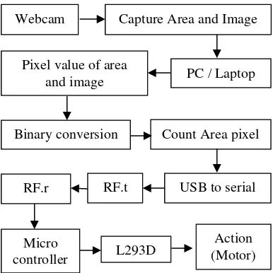
Fig. 4 Block diagram of the workflow engine
Description of Figure 4:
1. Webcam capture of existing conditions around the arena, and send to the PC
2. The pixel values of the image are determined arena 3. Binary converted values are calculated
4. Pixel arena is determined
5. The PC sends serial data via USB to serial 6. Serial RF transmitter
7. After received by the RF transmitter 8. Robot captured RF receiver
9. Data is sent to the micro 10. The robot moves
B. Design System
At this stage, the authors designed the study where the camera will be used. Fig 5 shows a block diagram inside the webcam
Fig. 5 Block Diagram Webcam
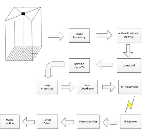
Fig 6 shows, early look of OpenCV program when illustrates two frames. The first frame at the beginning is the drawing frame, which is the place to draw the formed line, while the second frame is the actual frame position where the movement of robot starts to take action by following the direction line, drawn by drawing position. The beginning process to draw from the starting point to the end can be seen from Fig 7. The images clearly show that the drawing frame formed lines to produce a desired image, and will be
established and followed by the movement of the robot in accordance with what have been described.
Fig. 6 First Layout of the OpenCV
Fig. 7 A. Step 1 The robot began to detect in OpenCv B. Step 2 User started drawing in OpenCv C. Step 3 User began to move the cursor to form a line D. Step 4 left frame, the robot starts to move following the line in the
right frame
E. Step 5 when the robot has moved into position
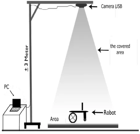
With the camera sensor, the environment capture process around the arena will be easier in determining the conducted pixel point. Fig 8 shows the area that covered the camera sensor in reading the size of the determined area. Furthermore, after capturing process or data, the image processing will be
A B
C D
E Webcam Capture Area and Image
Binary conversion Pixel value of area
and image PC / Laptop
Count Area pixel
USB to serial RF.t
Micro controller
RF.r
L293D
Action (Motor)
Image Sensor
Filter RGB
carried out. The process is carried out from the early stages of the threshold by converting the gray image into a binary image (the black or white pixels). Then it will be measured the obtained pixel from the captured camera process.
After the threshold process and pixel measurement, the PC will be sent to RF in robot to move according to previous step. The robot will receive input from the PC as command to process the image on track.
From the describing figure of robot motion , the directional movement of robot to form a drawing line will be shown on OpenCV. This process is vice versa from image processing of the camera, where the middle point will show the validated data during the pixel measurement. Fig 9 shows the flowchart of image processing in camera sensor in general.
Fig. 8 Robot Area
At the design stage of the research process undertaken previously described in Fig. 4, while the Fig. 9 describes the general block diagram of the capture arena who begins to move tool. Furthermore, the completion of a detailed block diagram is described in the block diagram below is more specific (Fig. 10).
Fig. 9 Basic Block Diagram
Fig. 10 Specific Block Diagram
C. Data Validation
Validation of previous designed system as a strengthen evidence tested experimentally, a program is made based on the design system. The program will be made in compiler of Open Source Computer Vision (OpenCV) [14]. The validation will be carried out by showing the correct algorithm, where the successful of calculation is indicated when the manual calculation is similar to program calculation and base on reference.
D. Computer Vision
Computer vision is trying to imitate the human vision. The human vision is very complex, where a human sees an object with its sight (eye) which then transfers to brain to be interpreted. This interpretation can be used to make a decision [15, 16].
Computer vision is an automated process that integrates a large number of processes for visual perception, such as image acquisition, image processing, classification, recognition (recognition), and makes a decision. Computer vision consists of techniques to estimate the characteristics of objects in the image, measure characteristics associated with the geometry of the object, and interpret the information geometry. It can be concluded in the following equation:
Vision = G + M+ I (1)
Where: G = Geometry M = Measurement I = Interpretation
A process in computer vision is divided into 3 (three) activities:
1. Obtaining or acquiring digital image.
3. Analyze and interpret the image using the processed results for a specific purpose, such as guiding the robot, controlling equipment, monitor the manufacture and others.
Image processing is actually the preliminary process in computer vision (preprocessing), whereas the pattern introduction is a process to be interpreted the image. Techniques in pattern introduction in computer vision have an important role to recognize the object.
Fig. 11 Simulation Image
IV. CONCLUSION
In conclusion, the state-chart method can be used to understand how making an avoider robot motion system for children learning media, at the same time simplify the computational system. The environment condition has been designed for this robot’s implementation (Fig.11). Microcontroller ATmega 16 will be used as the robot’s brain. To control the robot’s motion, two left-right DC motor will be used, equipped with 2 freely wheels for front and rear. Furthermore, the WI-Fi technology is utilized to show the result monitored by webcam to the PC. The targets to achieve from this study are:
1. To implement the robot system using state-chart method 2. To help the application of e-learning using robot
navigation.
3. To obtain an efficient algorithm in the robot navigation system.
4. To implement the image processing in determining the measurement of conversion points.
In general, the analysis system from the whole process is shown in Fig 12, where after the webcam capture the image, the result will be proceeded by changing the image color to a grayscale image, which then converted into black and white image or Thresholding. Afterwards, the process of downsizing the matrix quantization, measurement of robot distance to
edge of pixel line will be carried out in a PC using OpenCV program. Finally, the drawing track process will be completed.
Fig. 12 Flowchart of image pre-processing
ACKNOWLEDGMENT
This work was supported by Department of Computer Engineering and Faculty of Computer Science. University of Sriwijaya.
REFERENCES
[1] Engelbrecht, E. “A look at e-learning models: investigating their value
for developing an e-learning strategy”. Progressio 2003 ,25, 2, 38-47.
[2] Garrison, R. and Anderson, T. “E-learning in the 21stCentury: A
Framework for Research and Practice”, London: Routledge Falmer. 2003
[3] Barraquand, J., & Latombe, J. C. “Robot motion planning: A distributed
representation approach”. The International Journal of Robotics
Research, 1991. 10(6), 628-649.
[4] Choset, H. M. (Ed.).. Principles of robot motion: theory, algorithms, and
implementations. MIT press. (2005)
[5] Belta, C., Bicchi, A., Egerstedt, M., Frazzoli, E., Klavins, E., & Pappas, G. J. “Symbolic planning and control of robot motion” [grand challenges
of robotics]. Robotics & Automation Magazine, IEEE 2007, 14(1),
61-70.
[6] Lumelsky, V. J. “Algorithmic and complexity issues of robot motion in
an uncertain environment”. Journal of Complexity, 3(2), 146-182.
[7] Hemes, B., Fehr, D., & Papanikolopoulos, N. “Motion primitives for a
tumbling robot”. In Intelligent Robots and Systems, 2008. IROS 2008.
IEEE/RSJ International Conference on (pp. 1471-1476). IEEE.
[8] Dalley, S. A., Varol, H. A., & Goldfarb, M. “A method for the control of
multigrasp myoelectric prosthetic hands”. Neural Systems and
Rehabilitation Engineering,IEEE Transactions on, 20(1), 58-67.
[9] T. Merz, P. Rudol, and M. Wzorek, “Control system framework for
autonomous robots based on extended state machines”, in International
Conference on Autonomic and Autonomous Systems, ICAS ’06, p. 14
[10] Dressler, F., & Fuchs, G. “Energy-aware operation and task allocation of
autonomous robots”. In Robot Motion and Control, 2005. RoMoCo'05.
Proceedings of the Fifth International Workshop on (pp. 163-168). IEEE.
START
Diminution Quantization Matrix Changing the grayscale image into a
black and white image thresholding Change the image color to Grayscale image
Capture
Drawing track
[11] Eduardo Kac,. “The origin and development of robotic art”. The Journal of research into New Media Technologies Vol 7 No 1.pp76-86. 2001a
[12] Eduardo Kac,. “Towards a chronology of robotic art”. The Journal of
research into New Media Technologies Vol 7 No 1.pp 87-111.2001b
[13] Casey Wayne Smith.. “Material design for a robotic arts studio”. Master
of science-Thesis- Massachusetts Institute of Technology. 2002
[14] Bradski, Gary, and Adrian Kaehler. Learning OpenCV: Computer vision
with the OpenCV library. O'reilly, 2008.
[15] Schalkoff, Robert J. Digital image processing and computer vision. Vol.
286. New York: Wiley, 1989.
[16] Umbaugh, Scott E. Computer Vision and Image Processing: A Practical