CITYGML MODELLING FOR SINGAPORE 3D NATIONAL MAPPING
K. H. Soon* and V. H. S. Khoo
Land Survey Division, Singapore Land Authority, 55 Newton Road, #12-01, 307987 Singapore - (soon_kean_huat, victor_khoo)@sla.gov.sg
Commission VI, WG VI/4
KEY WORDS: CityGML, 3D Mapping, Nation-wide
ABSTRACT:
Since 2014, the Land Survey Division of Singapore Land Authority (SLA) has spearheaded a Whole-of-Government (WOG) 3D mapping project to create and maintain a 3D national map for Singapore. The implementation of the project is divided into two phases. The first phase of the project, which was based on airborne data collection, has produced 3D models for Relief, Building, Vegetation and Waterbody. This part of the work was completed in 2016. To complement the first phase, the second phase used mobile imaging and scanning technique. This phase is targeted to be completed by the mid of 2017 and is creating 3D models for Transportation, CityFurniture, Bridge and Tunnel. The project has extensively adopted the Open Geospatial Consortium (OGC)’s CityGML standard. Out of 10 currently supported thematic modules in CityGML 2.0, the project has implemented 8. The paper describes the adoption of CityGML in the project, and discusses challenges, data validations and management of the models.
* Corresponding author
1. WOG 3D NATIONAL MAPPING PROJECT
In 2014, SLA has started a Whole-of-Government (WOG) project called the 3D National Mapping to capture laser scanning data and imagery for the entire Singapore to create and maintain a national 3D map (Soon, et. al, 2015). The project, which is divided into two phases, is targeted to be completed by mid of this year (2017). Phase 1 collected data using airborne lidar scanning technology with imagery, while Phase 2 concentrated on mobile lidar scanning (with images) on the streets.
The project has extensively adopted OGC’s CityGML standard (OGC, 2012). Out of the 10 thematic modules currently supported in CityGML 2.0, the project has implemented 8. CityGML is chosen as information model due to its capability to support interoperability and to capture richer semantic information. With CityGML models, it will promote research and application developments to support a smart nation.
In what follows, Section 2 gives a brief introduction about CityGML 2.0. The section also includes the rationale of adopting CityGML and how the standard has been used in Singapore’s context. Section 3 demonstrates how the models have been produced and how they are looked like with some sample models being produced from the project. This section also discusses challenges and drawbacks in term of data collection and modelling. Section 4 and 5 explain the validations and data management of how these models are handled. Section 6 concludes the paper with potential applications and future outlook.
2. SINGAPORE CITYGML
2.1 CityGML 2.0
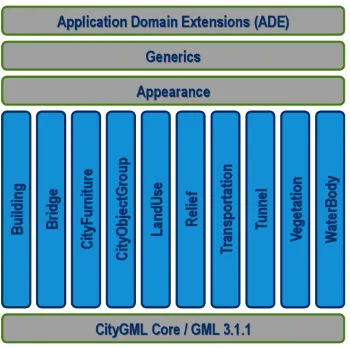
Open Geospatial Consortium (OGC) has defined CityGML (City Geography Markup Language) for modeling 3D city models. The current version of CityGML is 2.0 and contains modules like Relief, Building, CityFurniture, WaterBody, Bridge, Tunnel, Vegetation, Land Use and Transportation. CityGML defines classes, attributes and relations for topographic features with aspects of geometrical, topological, semantic and appearance (OGC, 2012). Different level of details can be captured from LOD (Level of Details) 0 to LOD 4. LOD 0 is represented as flat 3D surfaces like terrain or building footprints, while LOD 1 contains simple 3D blocks (with no texturing or appearance). LOD 2 represents topographic features with texturing and refined top structure. For instance for buildings, LOD 2 represents the actual shape of rooftop, LOD 3 models more detailed features and includes other external installations like windows and doors. LOD 4 Building includes internal installation modeling (van den Brink, et. al., 2013).
The models created in the project follow CityGML 2.0, which is the most current version when the project is conducted. It is understood that version 3.0 is still being developed at the OGC during the project implementation.
2.2 Thematic Modules
Figure 1. CityGML 2.0 with 10 supported Thematic Modules
In the project, except for CityObjectGroup and LandUse, all thematic modules have been implemented. That is to say, the CityGML models produced from the project include Building, Bridge, CityFurniture, Relief, Transportation, Tunnel, Vegetation and WaterBody.
The modular approach based on thematic modules is crucial to enable modelling and managing 3D topographic features more efficiently. With modelling according to different thematic modules, one can combine any modules as deemed necessary for a specific application. This is important especially when performance is a concern.
As XML-based, CityGML models also allow for automated validations. This is definitely a major cost-saving factor especially when the scale of the modelling covers the entire nation and involves many thematic modules, like what have been experienced in the project.
2.3 Localised Codelists
As a result of the semantics that have been defined in CityGML, a CityGML model is not only a 3D model but also an information model that enables computer systems to extract information from regardless of operating systems being used. For the models to be more meaningful locally, additional localised codelists have been defined during the project and appended to the existing standard codelists. These codelists have been published at the SLA’s website (http://www.sla.gov.sg/Press-Room/Circulars/Land-Survey). For example as shown in Figure 2, localised attributes of _AbstractBuilding_class have been appended with a prefix “sla” to the gml:id and the gml:name begins with 3000.
Figure 2. The localised codelist for _AbstractBuilding_class
2.4 Address and externalReference
Address information is also added to the LOD 2 Building models wherever the information is available from the existing 2D building footprints (more on this in Section 3 below). Figure 3 demonstrates the address details defined in the models.
Figure 3. Address details in LOD 2 Building
All models in the project have a unique identifier (i.e. UUID). Through these gml:ids, a referencing has been created between LOD 1 and LOD 2 models for Building and Transportation. For example, in Figure 4(a), a corresponding LOD 2 Transportation gml:id has been defined in the <externalReference> of LOD 1 Transportation model. Conversely, in Figure 4(b), the gml:id of LOD 1 Transportation has been defined in LOD 2 Transportation model. With this referencing, it helps to link up LOD 1 and LOD 2 models.
(a) In LOD 1 Transportation, corresponding LOD 2 Transportation’s gml:id
(b) In a LOD 2 Transportation model, the corresponding LOD 2 Transportation’s gml:id has been defined.
Figure 4. Cross-referencing has been created between LOD 1 and LOD 2 models
3. CITYGML MODELS
In order to manage the models more efficiently, the models have been indexed into a 1km X 1km tile to cover the entire nation and each tile has a unique identification.
3.1 3D Relief
relief. Figure 5 shows a 1-km2 tile Relief as LOD 0 triangulated surfaces.
Figure 5. Relief as LOD 0 triangulate surfaces
3.2 3D Building
LOD 2 Building models were created from aerial images and point cloud. The attributes of the building models such as Class, Usage and Function were populated from the existing 2D building footprints currently available in Singapore National Spatial Data Infrastructure (NSDI) called SG-Space. The 2D footprints have also been used to create LOD 1 building models with the building heights obtained from the airborne point cloud data.
There are over two hundred thousands building models for the entire nation. Each building is represented as one CityGML file, the reason being to flexibly manage the files. As opposed to grouping, for instance all CitiGML files for the same zone, which will overload the performance of the visualisation software, modelling individual building as one single CityGML file will allow data users to select flexibly the models they need for specific applications. As the planning zone has been defined in the Address element (see Figure 3), grouping can also be done if need be. Figure 6 depicts a sample of textured LOD 2 building model.
Using the airborne data collection technique to produce the building models has limited the level of detail of the buildings up to LOD 2. While the airborne data collection is efficient to map the nation at macro scale, at micro level building features like windows, doors, are not captured completely. These features are necessary to create LOD 3.
Although mobile data collection technique is used in Phase 2, the detailed building features can only be captured for buildings that are located near to the streets. To ensure a consistent level of details across the entire nation, only LOD 0 – LOD 2 building models have been created.
Figure 6. LOD 2 Building model
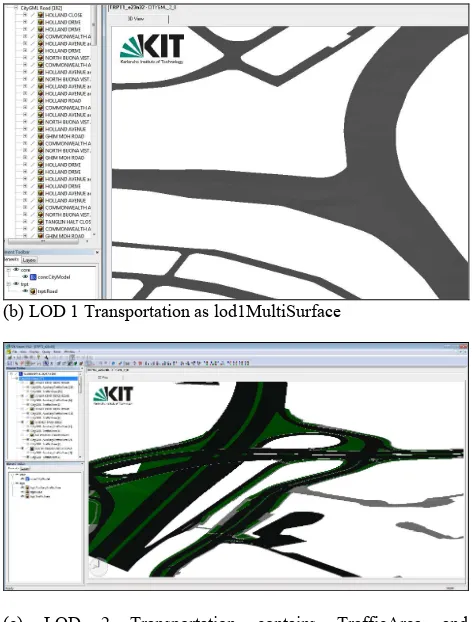
3.3 3D Transportation
The mobile point clouds data from Phase 2 have been used to model LOD 0, LOD 1, and LOD 2 Transportation. LOD 0 Transportation represents 3D linear network (to be specific lod0Network), which includes traffic flows. LOD 1 Transportation includes TransportationComplex like road, road kerbs, but excludes green areas and car parking lots. LOD 2 Transportation further classifies TransportationComplex into TrafficArea (e.g. footpath, road) and AuxiliaryTrafficArea (e.g. green areas, road kerb). LOD 2 includes LOD 1 plus other transportation features like car parking lots, green areas, etc. LOD 2 has richer in semantics and geometries than LOD 1. But it is also more resource-intensive when come to performance compared to LOD 1.
Similar to 3D Building, the attributes for the transportation models are populated from the existing 2D road network currently available on SG-Space.
The transportation models, which cover the distance over 5,500 kilometres across the entire nation, have also been partitioned in 1-km2 tile. Figure 7 demonstrates the samples for LOD 0 (Figure 7 (a)), LOD 1 (Figure 7 (b)) and LOD 2 (Figure 7 (c)) respectively.
(b) LOD 1 Transportation as lod1MultiSurface
(c) LOD 2 Transportation contains TrafficArea and AuxiliaryTrafficArea
Figure 7. LOD 0 Transportation, LOD 1 Transportation and LOD 2 Transportation.
Due to the connectivity nature of transportation network, it is challenging to model and manage the transportation models. Questions like where are the start and end of a road, which road should the intersection belong to are always raised. To resolve the issue, the transportation models have been produced in square tiles. The drawback of this approach is that when a network analysis is required, the models have to be connected to form a complete network.
3.4 3D CityFurniture
The modelling for CityFurniture is based on Explicit Geometry as opposed to Implicit Geometry. Explicit Geometry refers the model that is based on absolute coordinates (i.e. in Singapore’s SVY21 coordinate system), while Implicit Geometry means the models are based on a local coordinate system, which can be in 0,0,0 origin and formed based on certain transformation parameters (e.g. orientation) (OGC, 2012).
In this project the rationale (or rather the advantages) of considering ExplicitGeometry is twofold. One is that most of the current CityGML software only supports Explicit Geometry and not Implicit Geometry. When the models are shared in different platforms, this issue may limit the usage of the models. The other reason is to avoid the issue of broken reference link that may occur when disseminating the CityFurniture models. When the models are created, the link to the CityFurniture object will have to be fixed in the CityGML files. The issue of broken reference link can occur when migrating the models into different platforms for instance due to change of IT policy.
Explicit Geometry requires the actual object to be modelled as opposed to Implicit Geometry where the object can be made reference to an object library. This creates disadvantage to Explicit Geometry, which may cause overload to the performance. However with indexing the models into 1-km2 tiles, the performance for the visualisation of CityFurniture should be acceptable. A sample of City Furniture models is illustrated in Figure 8.
Figure 8. A sample of LOD 2 City Furniture models
3.5 3D Bridge
In LOD 2 Bridge, a bridge model combines a main bridge and a few BridgeConstructionElements. Bridge represents the main structure of the bridge, while BridgeConstructionElement consists of other parts of the bridge like the pillars supporting the bridge’s main structure. Similar to LOD 1 Building, LOD 1 Bridge represents a 3D bounding box extruded from the bridge footprint.
Bridge models in the project are divided into Road Bridges and Pedestrian Bridges. Figure 9 shows a sample of LOD 2 Road Bridge.
Figure 9. A sample of LOD 2 Road Bridge
3.6 3D Tunnel
Figure 10. A LOD 2 Tunnel model
3.7 3D WaterBody
As no bathymetry data have been collected for natural water bodies, 3D WaterBody has been produced up to LOD 1 with common water depth of 5m across all water bodies. As the number of water bodies is small, roughly around 300 for the entire nation, all LOD 1 WaterBody is represented in one single CityGML file. Figure 11 illustrates a sample of LOD 1 WaterBody.
Figure 11. LOD 1 WaterBody
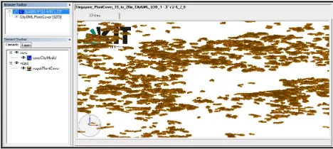
3.8 3D Vegetation
3D Vegetation is represented as PlantCover instead of SolidaryVegetationObject. A nation-wide tree modelling is a gigantic exercise by itself. By taking into consideration of time and cost, the project decided to model vegetation for the entire nation up to LOD 1 using the generalised PlantCover. Figure 12 depicts LOD 1 Vegetation as PlantCover for vegetations that are between 15 – 20 m tall.
Figure 12. LOD 1 Vegetation represented as PlantCover
4. VALIDATIONS
Analysis and simulation results are not reliable if the quality of the models is not ensured. Few open-source software tools have been used to validate the CityGML models for the following aspects:
• schema (e.g. for compliance and external reference) • themes (e.g. Building, Bridge)
• geometries (polygon and solid)
• semantics (e.g. wall surface, roof surface) • database import (e.g. data types)
These tools include FZK Viewer ( http://iai-typo3.iai.fzk.de/www-extern/index.php?id=1931), Val3dity (Biljecki, et. al, 2016), 3D CityDB Importer/Exporter (http://www.3dcitydb.org/), CityDoctor (Wagner, et. al, 2013) and FME. Due to the complexity of the models, errors were unavoidable when performing the validation checks (Biljecki, et. al 2016). To enhance the models, a number of iterations have been conducted.
3DCityDB Importer/Exporter has mainly been used to validate whether the models are indeed compliant with CityGML 2.0 schema and can be later imported into the database. As the tool is capable to validate many files at once, it serves as a useful first filter to ensure the checking for other aspects of the models can be performed later.
After the models are successfully validated through 3D CityDB Importer/Exporter, FZK Viewer is then used to check if the models are produced to the correct theme. Sometimes it is difficult to classify if a building is indeed a building and not a ship. Human judgement is often needed and the visualization with texture using FZK Viewer helps to make the decision.
To validate the geometries and semantics of the models, CityDoctor and Val3dity have been used. The tools ensure the topology between the geometries is correct. However, due to the data collection and modelling techniques, few unavoidable errors still exist, such as the planarity of surface. For instance, the building models are digitized manually from orthophotos. It is difficult to produce exactly flat surfaces.
5. DATA MANAGEMENT
Recognising the importance of maintaining these massive models, the division has been looking into managing the models in DBMS (Database Management System). Instead of exporting and importing the models for every change, a framework should be established to update the models directly to the spatial database using GIS software such as Bentley Map Enterprise (Figure 13).
Figure 13. Connection to 3D CityDB Schema with Bentley Map Enterprise
geometry column (Figure 14), this poses a technical challenge for GIS software to directly update the models.
Figure 14. Spatial table that contains multiple geometry columns
As a standard GIS only supports one geometry column for one spatial table, additional customisations are needed to update the multiple-geometry-column tables. Work has been carried out with GIS vendor like Bentley Systems to address this issue. The work is still in progress; thus far no outcome has been produced.
6. FUTURE OUTLOOK
After the project is completed, the models will be shared eventually to the Virtual Singapore platform to facilitate research and application developments for and by the government, academia and industry. As many applications can be benefited from 3D models (Biljecki, et. al, 2015), the team in SLA also works closely with research institutions for applications such as solar potential study, flood modelling, tree modelling, etc.
Solar potential study for instance has been conducted by some research centres in Singapore based on the building models produced from the Project. These research institutions have also used the building models for wind flow simulation.
The Relief model has also been useful for flood modelling. The Public Utility Board for instance has used the model for flood management. We believe through the sharing at the Virtual Singapore platform, more applications and research can be benefited from these datasets.
Having said that, we do foresee challenges ahead for using the datasets. CityGML is not a familiar format like ESRI’s Shapefiles, or Bentley’s DGN where everyone has been familiar with. There will be a learning curve for data users who need these datasets for their operations.
To update and maintain the models over times, few alternatives have been looked into such as the ground-based laser scanning / topographic survey, satellite images and Building Information Models (BIM). The recapturing using the techniques that had been used in the project may be a possibility as well.
Finally regarding the performance, thus far no test has been done. However, with the latest release of ArcGIS Pro from ESRI, the performance seems to be promising after loading substantially huge datasets from the Project into the software.
ACKNOWLEDGEMENTS
The authors would like to thank SLA’s 3D Mapping team and AAM for the great efforts they have put in to make the project successful. The first author particularly appreciates Carly Lambert from AAM for many fruitful discussions on CityGML modelling during the project. We would also like to thank the 3D Geoinfo community for developing great open source tools and for researching issues related to 3D geoinformation. Our 3D journey would not be smooth without all these helps.
REFERENCES
Biljecki, F., Stoter, J., Ledoux, H., Zlatanova, S. and Coltekin, A., 2015. Applications of 3D City Models: State of the Art Review. ISPRS International Journal of Geo-Information, 4, 2842-2889.
Biljecki, F., Ledoux, H., Du, X., Stoter, J., Soon, K. H. and Khoo, V. H. S., 2016. The Most Common Geometric and Semantic Errors in CityGML Datasets. ISPRS Ann.
Photogramm. Remote Sens. Spatial Inf. Sci., IV-2/W1, 13-22.
OGC, 2012. OGC City Geography Markup Language
(CityGML) Encoding Standard. Open Geospatial Consortium.
Document 12-019, version 2.0.0.
Soon, K. H., Low, E., Ng, Z. H. and Khoo, V., 2015. CityGML
Experience: From Validation to Database Management. 13th
South East Asian Survey Congress. 28–31 July 2015, Singapore.
Van den Brink, L., Stoter, J, and Zlatanova, S., 2013. Establishing A National Standard for 3D Topographic Data Compliant to CityGML. International Journal of Geographical
Information Science. 27(1): 92-113. Taylor & Francis.
Wagner, D., Wewetzer, M., Bogdahn, J., Alam, N., Pries, M. and Coors, V., 2013. Geometric-Semantical Consistency Validation of CityGML Models. In J. Pouliot et. al. (eds),
Progress and New Trends in 3D Geoinformation Sciences,