• Table of
Contents
Designing Enterprise Solutions with Sun™ Cluster 3.0 By Richard Elling, Tim Read
Publisher: Prentice Hall PTR Pub Date: December 01, 2001
ISBN: 0-13-008458-1 Pages: 302
Slots: 1
Designing Enterprise Solutions with Sun Cluster 3.0 is an introduction to architecting high available systems with Sun servers, storage, and the Sun Cluster 3.0 software.
Three recurring themes are used throughout the book: failures,
synchronization, and arbitration. These themes occur throughout all levels of system design. The first chapter deals with understanding these
relationships and recognizing failure modes associated with synchronization and arbitration. The second and third chapters review the building blocks and describe the Sun Cluster 3.0 software environment in detail. The remaining chapters discuss management servers and provide hypothetical case studies in which enterprise solutions are designed using Sun
• Table of
Contents
Designing Enterprise Solutions with Sun™ Cluster 3.0 By Richard Elling, Tim Read
Publisher: Prentice Hall PTR Pub Date: December 01, 2001
ISBN: 0-13-008458-1 Pages: 302 Slots: 1 Copyright Figures Tables Preface
Sun BluePrints Program
Who Should Use This Book
Before You Read This Book
How This Book Is Organized
Ordering Sun Documents
Accessing Sun Documentation Online
Related Books
Typographic Style
Shell Prompts in Command Examples
Acknowledgements
Richard Elling
Tim Read
Chapter 1. Cluster and Complex System Design Issues
Business Reasons for Clustered Systems
Failures in Complex Systems
Data Synchronization
Arbitration Schemes
Data Caches
Timeouts
Failures in Clustered Systems
Summary
Chapter 2. Enterprise Cluster Computing Building Blocks
Data Repositories and Infrastructure Services
Business Logic and Application Service
User Access Services: Web Farms
Compute Clusters
Technologies for Building Distributed Applications
Chapter 3. Sun Cluster 3.0 Architecture
System Architecture
Kernel Infrastructure
System Features
Cluster Failures
Design Goals
Services
Console Services
Sun Ray Server
Sun StorEdge SAN Surfer
Sun Explorer Data Collector
Sun Remote Services
Software Stack
Hardware Components
Network Configuration
Systems Management
Backup, Restore, and Recovery
Summary
Chapter 5. Case Study 1—File Server Cluster
Firm Description
Design Goals
Cluster Software
Recommended Hardware Configuration
Summary
Chapter 6. Case Study 2—Database Cluster
Company Description
Information Technology Organization
Design Goals
Business Case
Requirements
Design Priorities
Cluster Software
Recommended Hardware Configuration
Summary
Appendix A. Sun Cluster 3.0 Design Checklists
Business Case Considerations
Personnel Considerations
Top-Level Design Documentation
Environmental Design
Server Design
Shared Storage Design
Network Design
Software Environment Design
Security Considerations
Systems Management Requirements
Testing Requirements
Appendix B. Sun Cluster Technology History And Perspective
SPARCcluster PDB 1. x and SPARCcluster HA 1. x History
Sun Cluster 2. x
Sun Cluster 2.2 and 3.0 Feature Comparison
Appendix C. Data Center Guidelines
Hardware Platform Stability
System Component Identification
AC / DC Power
System Cooling
Network Infrastructure
Security
System Installation and Configuration Documentation
Change Control Practices
Maintenance and Patch Strategy
Component Spares
New Release Upgrade Process
Support Agreement and Associated Response Time
Backup-and-Restore Testing
Cluster Recovery Procedures
Summary
Appendix D. Tools
Fault Tree Analysis
Reliability Block Diagram Analysis
Failure Modes and Effects Analysis
Event Tree Analysis
Acronyms, Abbreviations, and Glossary
Copyright
© 2002 Sun Microsystems, Inc., 901 San Antonio Road, Palo Alto, CA 94303-4900 U.S.A. All rights reserved.
This product or document is distributed under licenses restricting its use, copying, distribution, and decompilation. No part of this product or document may be reproduced in any form by any means without prior written authorization of Sun and its licensors, if any. Third-party software, including font technology, is copyrighted and licensed from Sun suppliers.
Parts of the product may be derived from Berkeley BSD systems, licensed from the University of California. UNIX is a registered trademark in the U.S. and other countries, exclusively licensed through X/Open Company, Ltd.
Sun, Sun Microsystems, Sun BluePrints, SunUP, the Sun logo, AnswerBook, AnswerBook2, DLT, docs.sun.com, IPC, Solaris, Solstice Backup, Trusted Solaris, SunDocs, Sun Quad FastEthernet, SunFastEthernet, Sun StorEdge, SunPlex, OpenBoot, Sun Enterprise, Sun Enterprise Network Array, Sun Enterprise SyMON , Sun Fire, Sun HighGround, Starfire, iPlanet, Netra, SunTone, JumpStart, Solstice, Solstice DiskSuite, Solstice Backup, Solstice SyMON, Ultra Enterprise, Java, Jiro, JavaServer Pages, JSP, J2EE, JDBC, Sun Ray, Sun RSM Array, SunSwift, Enterprise JavaBeans, EJB, Sun HPC ClusterTools, SPARCcenter, SPARCcluster, SPARCserver, SPARCstorage, Sun Professional Services, SunSolve,
SPARCcluster, PDB, Prism, RSM, and Write Once, Run Anywhere are trademarks, registered trademarks, or service marks of Sun Microsystems, Inc. in the United States and other
countries. All SPARC trademarks are used under license and are trademarks or registered trademarks of SPARC International, Inc. in the U.S. and other countries. Products bearing SPARC trademarks are based upon an architecture developed by Sun Microsystems, Inc. CMS is a trademark or registered trademark of Eastman Kodak Company in the United States and other countries.
ORACLE is a registered trademark of Oracle Corporation. Netscape is a trademark or
registered trademark of Netscape Communications Corporation in the United States and other countries. Legato NetWorker is a registered trademark of Legato Systems, Inc. Adobe is a registered trademark of Adobe Systems, Incorporated.
The OPEN LOOK and Sun Graphical User Interface was developed by Sun Microsystems, Inc. for its users and licensees. Sun acknowledges the pioneering efforts of Xerox in
researching and developing the concept of visual or graphical user interfaces for the computer industry. Sun holds a non-exclusive license from Xerox to the Xerox Graphical User Interface, which license also covers Sun's licensees who implement OPEN LOOK GUIs and otherwise comply with Sun's written license agreements.
DOCUMENTATION IS PROVIDED "AS IS" AND ALL EXPRESS OR IMPLIED CONDITIONS, REPRESENTATIONS AND WARRANTIES, INCLUDING ANY IMPLIED WARRANTY OF MERCHANTABILITY, FITNESS FOR A PARTICULAR PURPOSE OR NON-INFRINGEMENT, ARE DISCLAIMED, EXCEPT TO THE EXTENT THAT SUCH DISCLAIMERS ARE HELD TO BE LEGALLY INVALID.
Editorial/production supervisor: Nicholas Radhuber Cover design director: Jerry Votta
Cover designer: Kavish & Kavish Digital Publishing Design Manufacturing manager: Alexis R. Heydt
Marketing manager: Debby vanDijk Acquisitions manager: Gregory G. Doench Sun Microsystems Press
Marketing manager: Michael Llwyd Alread Publisher: Rachel Borden
Figures
FIGURE 1-1 HA System Failure Response
FIGURE 1-2 Cache Latency Versus Cost
FIGURE 1-3 Nested Timing Diagram—Example
FIGURE 1-4 Nested Timing Diagram With Timeout
FIGURE 1-5 Stable System With Timeout
FIGURE 1-6 Unstable System With Timeout
FIGURE 2-1 SAP R/3 Application Architecture
FIGURE 2-2 Multitiered Model
FIGURE 2-3 iPlanet Application Server Overview
FIGURE 2-4 iPlanet Application Server Processes
FIGURE 2-5 Web Hosting Service Ladder Approach—Load Balanced and Load Balancing
FIGURE 2-6 Sun Parallel File System, High-Level View
FIGURE 3-1 I/O Overhead of Campus Clustering Versus Replication
FIGURE 3-2 Sun Cluster 3.0 System Hardware Diagram
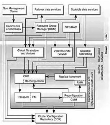
FIGURE 3-3 Relationship Between Sun Cluster Components
FIGURE 3-4 Mini-Transaction Replicated Object Sequence
FIGURE 3-5 Clustered Pair Topology
FIGURE 3-6 N+1 Topology
FIGURE 3-7 Pair+M Topology
FIGURE 3-8 Local and Dual-Hosted Devices
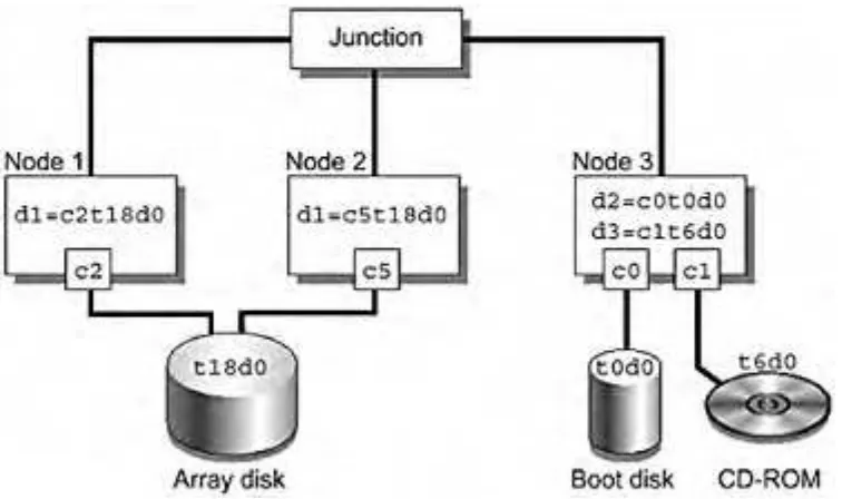
FIGURE 3-9 DID Numbering for a Three-Node Cluster
FIGURE 3-10 Global File Service Architecture
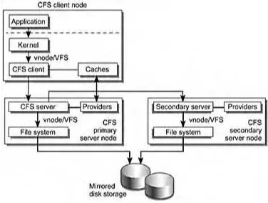
FIGURE 3-11 CFS Read Mechanism
FIGURE 3-13 Four-Node Cluster With Two Subnets and Two Global IP Addresses
FIGURE 3-14 Switch-Connected and Back-to-Back Private Interconnects
FIGURE 3-15 Failover Resource Group Configuration—Example
FIGURE 4-1 SRS High-Level Architectural Block Diagram
FIGURE 4-2 Environment Logical Connectivity
FIGURE 4-3 Management Server Network Configuration
FIGURE 5-1 NFS Cluster Logical Configuration
FIGURE 5-2 NFS Cluster Network Configuration Options
FIGURE 5-3 NFS Cluster Rack Configuration
FIGURE 5-4 Expected Backup Times
FIGURE 6-1 Top-Level Architecture for Oracle 9i RAC Database System
FIGURE 6-2 Active Users
FIGURE 6-3 Oracle 9i RAC Architecture
FIGURE 6-4 Oracle 9i RAC Logical Cache
FIGURE 6-5 Two-Node Cache Fusion
FIGURE 6-6 Sun Cluster Configuration
FIGURE 6-7 Sun StorEdge D240 Media Tray—Front View
FIGURE 6-8 Sun StorEdge D240 Media Tray—SCSI Bus Configurations
FIGURE 6-9 Production Server Boot Disk Environment
FIGURE 6-10 Multiple Failure Scenario
FIGURE 6-11 Alternate Design for Production Server Boot Disk Environment
FIGURE 6-12 The Company's Network Design
FIGURE 6-13 Sun Fire Cabinet Power Distribution
FIGURE B-1 Sun Cluster 2.2 Logical Host
FIGURE C-1 Data Center Floor Plan Grid Diagram—System xyz Is Located at Grid Coordinate b4
FIGURE D-3 Functional Block Structure Analysis
FIGURE D-4 Fault Tree Analysis of Boot, Root, and Swap Disk Subsystem
FIGURE D-5 Mirrored Disk Subsystem Reliability Block Diagram
FIGURE D-6 Mirrored Sun StorEdge D240 Media Tray—Event Tree Analysis
Tables
TABLE 1-1 Common 10BASE-T Ethernet Failure Modes
TABLE 1-2 Reported and Correctable Errors
TABLE 3-1 Global File Service Benefits for Application Executables
TABLE 3-2 CFS and NFS Differences
TABLE 3-3 Resource Type Properties
TABLE 5-1 Major Feature Priorities
TABLE 5-2 High-Level Features of NFS Versions 2 and 3
TABLE 5-3 Management Server and Support Components Parts List
TABLE 5-4 NFS Cluster Node Parts List
TABLE 5-5 NFS Cluster Node Network Port Assignments
TABLE 6-1 Planned Service Schedule
TABLE 6-2 Major Feature Priorities
TABLE 6-3 Oracle 9i RAC Cluster Software Stack
TABLE 6-4 Sun Fire 4800 Server Node Parts List
TABLE 6-5 Sun Fire 4800 Node I/O Configuration
TABLE 6-6 Oracle 9i RAC Shared Storage Parts List
TABLE 6-7 Sun StorEdge T3 Array With Sun Cluster Configurations
TABLE B-1 Sun Cluster 2.2 and 3.0 Terminology Differences
TABLE D-1 FMEA Table Example
TABLE D-2 Key for FMEA Severity, Likelihood, and Detection
Preface
Designing Enterprise Solutions with Sun Cluster 3.0 is published under the auspices of the Sun BluePrints™ program. This book is written for systems architects and engineers who design clustered systems. It describes the fundamental systems engineering concepts behind clustered computer systems and discusses solutions and trade-offs in some detail.
Systems engineering is concerned with the creation of the entire answer to some real-life problem, with the answer based on science and technology [Ramo 65]. Systems engineers deal with the people/process/technology balance and multivariate problems. They integrate huge numbers of components, unwanted modes, partial requirements, indefinite answers,
probabilities of external conditions, the testing of complicated systems, and all of the natural sciences behind the technology. This book contains little detail on specific engineering solutions; instead, it focuses on the fundamental concepts that are used repeatedly in the design of clustered computer systems.
This book provides detailed examples of the effective use of clustered system technology, along with information about the features and capabilities of the Sun™ Cluster 3.0 system (hereafter referred to as Sun Cluster 3.0).
Three concepts are addressed throughout the book—failures, synchronization, and arbitration. These three concepts are examined repeatedly at all levels of the systems design.
First, complex systems tend to fail in complex ways. Implementing clustered systems can prevent some of these failures. Businesses implement clusters when the cost of implementing and maintaining a cluster is less than the cost of a service outage. While anticipating the many ways in which services hosted on clusters can fail, you must be diligent when designing clustered systems to meet business needs.
Second, clustered systems use redundancy to ensure that no single point of failure renders the data inaccessible. However, adding redundancy to a system inherently creates a
synchronization problem—the multiple copies of the data must remain synchronized, or chaos ensues.
Third, redundancy and failures create arbitration problems. Given two copies of data that are potentially out of sync, which is the correct copy? Similarly, any data service operating on the data must do so with the expectation that no other data service is operating on the same data without its knowledge. These arbitration problems are solved with services supplied by the cluster infrastructure.
Sun BluePrints Program
The mission of the Sun BluePrints™ program is to empower Sun's customers with the technical knowledge required to implement reliable, extensible, and secure information systems within the data center using Sun products. This program provides a framework to identify, develop, and distribute best practices information that applies across the Sun product lines. Experts in technical subjects in various areas contribute to the program and focus on the scope and advantages of the information.
The Sun BluePrints program includes books, guides, and online articles. Through these vehicles, Sun can provide guidance, installation and implementation experiences, real-life scenarios, and late-breaking technical information.
The monthly electronic magazine, Sun BluePrints OnLine, is located on the web at
http://www.sun.com/blueprints. To be notified about updates to the Sun BluePrints Program, please register on this site.
Who Should Use This Book
This book is primarily intended for readers with varying degrees of experience with or knowledge of clustered system technology. Detailed examples of using this technology effectively are provided in combination with the features and capabilities of the Sun Cluster 3.0 software.
Before You Read This Book
You should be familiar with the basic system architecture and design principles, as well as the administration and maintenance functions of the Solaris™ operating environment. You should also have an understanding of standard network protocols and topologies.
How This Book Is Organized
This book has six chapters and four appendixes: Cluster and Complex System Design Issues Enterprise Cluster Computing Building Blocks Sun Cluster 3.0 Architecture
Management Server
Case Study 1—File Server Cluster Case Study 2—Database Cluster Sun Cluster 3.0 Design Checklists
Sun Cluster Technology History and Perspective Data Center Guidelines
Tools
Chapter 1 introduces the problems that clustered systems try to solve. Emphasis is placed on failures, synchronization, and arbitration. Complex systems tend to fail in complex ways, so thinking about the impact of failures on systems should be foremost in the mind of the systems engineer. Synchronization is key to making two or more things look like one thing, which is very important for redundant systems. Arbitration is the decision-making process—what the system does when an event occurs or does not occur.
Chapter 2 reviews infrastructure business component building blocks—file, database, and name services, application services, and web services—and examines how clustering technology can make them highly available and scalable.
Chapter 3 describes the Sun Cluster 3.0 product architecture. This is the cornerstone of
building continuously available services using Sun products. Sun Cluster 3.0 software includes many advanced features that enable the systems architect to design from the services
perspective, rather than the software perspective.
Chapter 4 covers a Sun Cluster 3.0 management server example. This chapter describes the basic infrastructure services and a management server that provides these services first. This management server is used in the clustered systems solutions described in subsequent chapters.
Chapters 5 and 6 contain two hypothetical case studies—a low-cost file service and online database services. Each case study describes the business case and defines the requirements of the customer. These solutions are used to derive the design priorities that provide direction to the systems architect when design trade-offs must be made. Next, these chapters describe the system design, discussing the systems design methodology, and exploring in detail some of the design trade-offs that face the systems architect.
Appendix A contains a series of design checklists for the new Sun Cluster 3.0 product.
Appendix B provides an insight into the genesis of the new Sun Cluster 3.0 product and contrasts the features of Sun Cluster 2.2 with those of Sun Cluster 3.0.
Appendix C contains guidelines for data center design that supports highly available services.
Appendix D is a brief survey of tools that systems architects and engineers find useful when designing or analyzing highly available systems.
Ordering Sun Documents
The SunDocsSM program provides more than 250 manuals from Sun Microsystems, Inc. If you live in the United States, Canada, Europe, or Japan, you can purchase documentation sets or individual manuals through this program.
Accessing Sun Documentation Online
The docs.sun.com web site enables you to access Sun technical documentation online. You can browse the docs.sun.com archive or search for a specific book title or subject. The URL is
http://docs.sun.com/.
Related Books
The following table lists books that provide additional useful information.
Title Author and Publisher
ISBN Number/Part Number/URL Sun Cluster Environment Sun
Cluster 2.2
Enrique Vargas, Joseph Bianco, and David Deeths Sun Microsystems Press/Prentice Hall, Inc. (2001)
0-13-041870-6
Backup and Restore Practices for Sun Enterprise Servers
Stan Stringfellow, Miroslav Klivansky, and Michael Barto Sun Microsystems Press/Prentice Hall, Inc. (2000)
0-13-089401-X
System Interface Guide Sun Microsystems 806-4750-10 Multithreaded Programming Guide Sun Microsystems 806-5257-10
Sun Cluster 3.0 7/01 Collection Sun Microsystems http://www.sun.docs and
AnswerBook2™ Building a JumpStart Infrastructure Alex Noordergraaf
Sun Microsystems
http://www.sun.com/blueprints
Cluster Platform 220/1000
Architecture—A Product from the SunTone Platforms Portfolio
Enrique Vargas Sun Microsystems
Sun BluePrints OnLine article
http://www.sun.com/blueprints
Typographic Style
Typeface Meaning Examples
AaBbCc123 Names of commands, files,
and directories, and URLs
Edit your .login file. Use ls -a to list all files. machine_name % You have mail.
http://www.sun.com
AaBbCc123 Text entered into the
system (bold)
machine_name % su Password: AaBbCc123 Text displayed on the
monitor
Text varies with output
AaBbCc123 Book titles, new words or terms, words to be
emphasized
Read Chapter 6 in the User's Guide. These are called class options. You must be superuser to do this.
Command-line variable; replace with a real name or value
To delete a file, type rm filename.
Shell Prompts in Command Examples
The following table identifies the default system prompt and superuser prompt for the C shell, Bourne shell, and Korn shell.
Shell Prompt
C shell machine_name%
C shell superuser machine_name#
Bourne shell and Korn shell $
Bourne shell and Korn shell superuser #
Acknowledgements
The authors would especially like to thank Chuck Alexander whose vision and drive behind the Sun BluePrints program has made it so successful; Shuroma Herekar and Barbara Jugo for supporting the writers, editors, and illustrators who made it all possible; and of course Gary Rush, for managing the Blueprints projects.
This book was conceived, written, reviewed, edited, produced, and printed in less than six months. Publication would not have been possible without the collaboration and cooperation of the subject matter experts, writer, reviewers, editors, and artist, who gave its development top priority, while continuing to perform their usual duties.
We would like to acknowledge and thank the cluster experts and reviewers who helped shape the technical content of this book, all of them—Mike Arwood, Joseph Bianco, Michael Byrne, Ralph Campbell, Al Clepper, David Deeths, Tom Cox, Steven Docy, Andrew Hisgen, Mark Kampe, Yousef Khalidi, Peter Lees, James MacFarlane, James McPherson, Kim Merriman, Hossein Moiin, Declan Murphy, Sohrab Modi, David Nelson-Gal, Dan Orbach, Shankar Pasupathy, Ted Persky, Ira Pramanick, Marty Rattner, Nicolas Solter, Ronnie Townsend, Nancy Tu, and Enrique Vargas—for their input and support. And, to the entire Sun Cluster engineering team, well done!
A special thanks to Dany Galgani, who is one of the most responsive and talented illustrators at Sun Microsystems, for creating and revising more than 50 illustrations in less than 15 days; and Rashmi Shah, who helped input the editorial comments in the deadline crunch.
Thanks to George Wood, our mostly patient, tenacious, and tireless technical writer and editor for blending the diverse writing styles of the subject matter experts, authors, and reviewers from several different countries into the finished product.
We would also like to acknowledge and thank Regina Elling, Rex Casey, Billie Markim, Linda Wiesner, and Mary Lou Nohr, for editing the book and providing invaluable
developmental, organizational, trademark, and glossary contributions; and Cathy Miller for creating a superb index.
Richard Elling
I'd like to specially thank Regina, who always makes sure my writing is clear and puts up with my long hours at the keyboard. Thanks to Boca, who contributed much to the early
conversations about this book. And, of course, Rusty, who is always along for the ride. I'd also like to thank Enrique Vargas and Ted Persky for their contributions to the book.
Tim Read
I would like to start by thanking Hazel for the love, support, and cups of tea provided as the deadlines approached. I would also like to thank my manager, Keith Glancey, for allowing me time to write this book. I am eternally grateful to my parents (all of them!), without whose support I would never have made it this far. And finally, I would like to return the compliment to Brian, Cindy and Shaun.
Chapter 1. Cluster and Complex System Design Issues
This chapter addresses the following topics:
The need for a business to have a highly available, clustered system System failures that influence business decisions
Factors to consider when designing a clustered system
Failure modes specific to clusters, synchronization, and arbitration
To understand why you are designing a clustered system, you must first understand the business need for such a system. Your understanding of the complex system failures that can occur in such systems will influence the decision to use a clustered system and will also help you design a system to handle such failures. You must also consider issues such as data synchronization, arbitration, caching, timing, and clustered system failures—split brain, multiple instances, and amnesia—as you design your clustered system.
Once you are familiar with all the building blocks, issues and features that enable you to design an entire clustered system, you can analyze the solutions that the Sun Cluster 3.0 software offers to see how it meets your enterprise business needs and backup, restore, and recovery requirements.
The sections in this chapter are:
Business Reasons for Clustered Systems Failures in Complex Systems
Data Synchronization Arbitration Schemes Data Caches
Timeouts
Failures in Clustered Systems Summary
Business Reasons for Clustered Systems
Businesses build clusters of computers to improve performance or availability. Some products and technologies can improve both. However, much clustering activity driving the computer industry today is focused on improving service availability.
Downtime is a critical problem for an increasing number of computer users. Computers have not become less reliable, but users now insist on greater degrees of availability. As more businesses depend on computing as the backbone of their operation, around-the-clock availability of services becomes more critical.
Downtime can translate into lost money for businesses, potentially large amounts of money. Large enterprise customers are not the only ones to feel this pinch. The demands for mission-critical computing have reached the workgroup, and even the desktop. No one today can afford downtime. Even the downtime required to perform maintenance on systems is under pressure. Computer users want the systems to remain operational while the system
administrators perform system maintenance tasks.
Businesses implement clusters for availability when the potential cost of downtime is greater than the incremental cost of the cluster. The potential cost of downtime can be difficult to predict accurately. To help predict this cost, you can use risk assessment.
Risk Assessment
Risk assessment is the process of determining what results when an event occurs. For many businesses, the business processes themselves are as complex as the computer systems they rely on. This significantly complicates the systems architect's risk assessment. It may be easier to make some sort of generic risk assessment in which the business risk can be indicted as cost. Nevertheless, justifying the costs of a clustered system is often difficult unless one can show that the costs of implementing and supporting a cluster can reduce the costs of
downtime. Since the former can be measured in real dollars and the latter is based on a multivariate situation with many probability functions, many people find it easier to relate to some percentage of "uptime."
Clusters attempt to decrease the probability that a fault will cause a service outage, but they cannot prevent it. They do, however, limit the maximum service outage time by providing a host on which to recover from the fault.
Computations justifying the costs of a cluster must not assume zero possibility of a system outage. Prospect theory is useful to communicate this to end users in such a situation. To say the system has "a 99 percent chance of no loss" is preferable to "a 1 percent chance of loss." However, for design purposes, the systems architect must consider carefully the case where there is 1 percent chance of loss. You must always consider the 1 percent chance of loss in your design analysis. After you access the risks of downtime, you can do a more realistic cost estimate.
systems have both funding and time constraints.
Nonrecurring expenses include hardware and software acquisition costs, operator training, software development, and so forth. Normally, these costs are not expected to recur. The nonrecurring hardware costs of purchasing a cluster are obviously greater than an equivalent, single system. Software costs vary somewhat. There is the cost of the cluster software and any agents required. An additional cost may be incurred as a result of the software licensing agreement for any other software. In some cases, a software vendor may require the purchase of a software license for each node in the cluster. Other software vendors may have more flexible licensing, such as per-user licenses.
Recurring costs include ongoing maintenance contracts, consumable goods, power, network connection fees, environmental conditioning, support personnel, and floor space costs. Almost all system designs must be justified in economic terms. Simply put, is the profit generated by the system greater than its cost? For systems that do not consider downtime, economic justification tends to be a fairly straightforward calculation.
where:
Plifetime is the profit over the lifetime of the system.
Rlifetime is the revenue generated by the system over its lifetime. Cdowntime is the cost of any downtime.
Cnonrecurring is the cost of nonrecurring expenses. Crecurring is the cost of any recurring expenses.
During system design these costs tend to be difficult to predict accurately. However, they tend to be readily measurable on well-designed systems.
The cost of downtime is often described in terms of the profit of uptime.
where:
tdown is the duration of the outage. Puptime is the profit made during tup. tup is the time the system had been up.
For most purposes, this equation suffices. What is not accounted for in this equation is the opportunity cost. If a web site has competitors and is down, a customer is likely to go to one of the competing web sites. This defection represents an opportunity loss that is difficult to quantify.
The pitfall in using such an equation is that the Puptime is likely to be a function of time. For example, a factory that operates using one shift makes a profit only during the shift hours. During the hours that the factory is not operating, the Puptime is zero, and consequently the Cdowntime is zero.
where:
Puptime(t) =Pnominal, when t is during the work hours = 0, all other times
Another way to show the real cost of system downtime is to weight the cost according to the impact on the business. For example, a system that supports a call center might choose impacted user minutes (IUM), instead of a dollar value, to represent the cost of downtime. If 1,000 users are affected by an outage for 5 minutes, the IUM value is 1,000 users times 5 minutes, or 5,000 IUMs. This approach has the advantage of being an easily measured metric. The number of logged-in users and the duration of any outage are readily measurable
quantities. A service level agreement (SLA) that specifies the service level as IUMs can be negotiated. IUMs can then be translated into a dollar value by the accountants.
Another advantage of using IUMs is that the service provided to the users is measured, rather than the availability of the system components. SLAs can also be negotiated on the basis of service availability, but it becomes difficult to account for the transfer of the service to a secondary site. IUMs can be readily transferred to secondary sites because the measurement is not based in any way on the system components.
Failures in Complex Systems
This section discusses failure modes and effects in complex systems. From this discussion you can gain an appreciation of how complex systems can fail in complex ways. Before you can design a system to recover from failures, you must understand how systems fail.
Failures are the primary focus of the systems architect designing highly available (HA) systems. Understanding the probability, causes, effects, detection, and recovery of failures is critical to building successful HA systems. The professional HA expert has many years of study and experience with a large variety of esoteric systems and tools that are used to design HA systems. The average systems architect is not likely to have such tools or experience but will be required to design such systems. Fortunately, much of the detailed engineering work is already done by vendors, such as Sun Microsystems, who offer integrated HA systems. A typical systems design project is initially concerned with defining "what the system is supposed to do." The systems architect designing highly available clusters must also be able to concentrate on "what the system is not supposed to do." This is known as testing for unwanted modes, which can occur as a result of integrating components that individually perform
properly but may not perform together as expected. The latter can be much more difficult and time consuming than the former, especially during functional testing. Typical functional tests attempt to show that a system does what it is supposed to do. However, it is just as important, and more difficult, to attempt to show that a system does not do what it is not supposed to do. A defect is anything that, when exercised, prevents something from functioning in the manner in which it was intended. The defect can, for example, be due to design, manufacture, or misuse and can take the form of a badly designed, incorrectly manufactured, or damaged hardware or software component. An error usually results from the defect being exercised, and if not corrected, may result in a failure.
Examples of defects include:
Hardware factory defect—A pin in a connector is not soldered to a wire correctly, resulting in data loss when exercised.
Hardware field defect—A damaged pin no longer provides a connection, resulting in data loss when exercised.
Software field defect—An inadvertently corrupted executable file can cause an application to crash.
An error occurs when a component exhibits unintended behavior and can be a consequence of: A defect being exercised
A component being used outside of its intended operational parameters
A fault is usually a defect, but possibly an imprecise error, and should be qualified. "Fault" may be synonymous with bug in the context of software faults [Lyu95], but need not be, as in the case of a page fault.
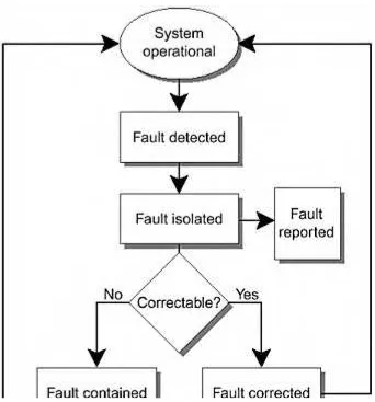
Highly available computer systems are not systems that never fail. They experience, more or less, the same failure rates on a per component basis as any other systems. The difference between these types of systems is how they respond to failures. You can divide the basic process of responding to failures into five phases.
FIGURE 1-1 shows the five phases of failure response: 1. Fault detection
2. Fault isolation to determine the source of the fault and the component or field-replaceable unit (FRU) that must be repaired
3. Fault correction, if possible, in the case of automatically recoverable components, such as error checking and correction (ECC) memory
4. Failure containment so that the fault does not propagate to other components 5. System reconfiguration so you can repair the faulty component
Fault Detection
Fault detection is an important part of highly available systems. Although it may seem simple and straightforward, it is perhaps the most complex part of a cluster. The problem of fault detection in a cluster is an open problem—one for which not all solutions are known. The Sun Cluster strategy for solving this problem is to rely on industry-standard interfaces between cluster components. These interfaces have built-in fault detection and error reporting. However, it is unlikely that all failure modes of all components and their interactions are known.
While this may sound serious, it is not so bad when understood in the context of the cluster. For example, consider unshielded twisted pair (UTP), 10BASE-T Ethernet interfaces. Two classes of failures can affect the interface—physical and logical.
These errors can be further classified or assigned according to the four layers of the TCP/IP stack, but for the purpose of this discussion, the classification of physical and logical is sufficient. Physical failures are a bounded set. They are often detected by the network interface card (NIC). However, not all physical failures can be detected by a single NIC, nor can all physical failures be simulated by simply removing a cable.
Knowing how the system software detects and handles error conditions as they occur is important to a systems architect. If the network fails in some way, the software should be able to isolate the failure to a specific component.
For example, TABLE 1-1 lists some common 10BASE-T Ethernet failure modes. As you can see from this example, there are many potential failure modes. Some of these failure modes are not easily detected.
Table 1-1. Common 10BASE-T Ethernet Failure Modes Description Type Detected by Detectability
Cable unplugged Physical NIC Yes, unless Software Query Enable (SQE) is enabled
Cable shorted Physical NIC Yes
Cable wired in reverse polarity
Physical NIC Yes
Cable too long Physical NIC (in some cases only)
Cable receive pair wiring failure
Physical NIC Yes, unless SQE is enabled Cable transmit pair
wiring failure
Physical Remote device
Yes, unless SQE is enabled Electromagnetic
interference (EMI)
Physical NIC (in some cases only)
Difficult, because the errors may be intermittent with the only detection being changes in the BER Duplicate medium access control address (MAC) Logical Solaris operating environment Yes Duplicate IP address Logical Solaris operating environment Yes Incorrect IP network address
Logical Not automatically detectable for the general case
No response from remote host
Logical Sun Cluster software
Sun Cluster software uses a series of
progressive tests to try to establish connection to the remote host
Note
You may be tempted to simulate physical or even logical network errors by disconnecting cables, but this does not simulate all possible failure modes of the physical network interface. Full physical fault simulation for networks can be a complicated endeavor.\
Probes
Probes are tools or software that you can use to detect most system faults and to detect latent faults. You can also use probes to gather information and improve the fault detection.
Hardware designs use probes for measuring environmental conditions such as temperature and power. Software probes query service response or act like end users completing transactions. You must put probes at the end points to effectively measure end-to-end service level. For example, if a user community at a remote site requires access to a service, a probe system must installed at the remote site to measure the service and its connection to the end users. It is not uncommon for a large number of probes to exist in an enterprise that provides mission-critical services to a geographically distributed user base. Collecting the probe status at the operations control center that supports the system is desirable. However, if the communications link between the probe and operations control center is down, the probe must be able to collect and store status information for later retrieval. For more information on probes, see "Failure Detection".
To detect latent faults in hardware, you can use special test software such as the Sun
Management Center Hardware Diagnostic Suite (HWDS) software. The HWDS allows you to perform tests that exercise the hardware components of a system at scheduled intervals. Because these tests consume some system resources, they are done infrequently. Detected errors are treated as normal errors and reported to the system by the normal error reporting mechanisms.
The most obvious types of latent faults are those that exist but are not detected during the testing process. These include software bugs that are not simulated by software testing, and hardware tests that do not provide adequate coverage of possible faults.
Fault Isolation
Fault isolation is the process of determining, from the available data, which component caused a failure. Once the faulty component is identified or isolated, it can be reset or replaced with a functioning component.
The term fault isolation is sometimes used as a synonym for fault containment, which is the process of preventing the spread of a failure from one component to others.
For analysis of potential modes of failure, it is common to divide a system into a set of disjointed fault isolation zones. Each error or failure must be attributed to one of these zones. For example, a FRU or an application process can represent a fault isolation zone.
When recovering from a failure, the system can reset or replace numerous components with a single action. For example, a Sun Quad FastEthernet™ card has four network interfaces located on one physical card. Because recovery work is performed on all components in a fault recovery zone, replacing the Sun Quad FastEthernet card affects all four network interfaces on the card.
Fault Reporting
Fault reporting notifies components and humans that a fault has occurred. Good fault reporting with clear, unambiguous, and concise information goes a long way toward improving system serviceability.
Berkeley Standard Distribution (BSD) introduced the syslogd daemon as a general- purpose
message logging service. This daemon is very flexible and network aware, making it a popular interface for logging messages. Typically, the default syslogd configuration is not sufficient
for complex systems or reporting structures. However, correctly configured, syslogd can
efficiently distribute messages from a number of systems to centralized monitoring systems. The logger command provides a user level interface for generating syslogd messages and is
Not all fault reports should be presented to system operators with the same priority. To do so would make appropriate prioritized responses difficult, particularly if the operator was
inexperienced. For example, media defects in magnetic tape are common and expected. A tape drive reports all media defects it encounters, but may only send a message to the operator when a tape has exceeded a threshold of errors that says that the tape must be replaced. The tape drive continues to accumulate the faults to compare with the threshold, but not every fault generates a message for the operator.
Faults can be classified in terms of correctability and detectability. Correctable faults are faults that can be corrected internally by a component and that are transparent to other components (faults inside the black box). Recoverable faults, a superset of correctable faults, include faults that can be recovered through some other method such as retrying transactions, rerouting through an alternate path, or using an alternate primary. Regardless of the recovery method, correctable faults are faults that do not result in unavailability or loss of data. Uncorrectable errors do result in unavailability or data loss. Unavailability is usually measured over a discrete time period and can vary widely depending on the SLAs with the end users. Reported correctable (RC) errors are of little consequence to the operator. Ideally, all RC errors should have soft-error rate discrimination algorithms applied to determine whether the rate is excessive. An excessive rate may require the system to be serviced.
Error correction is the action taken by a component to correct an error condition without exposing other components to the error. Error correction is often done at the hardware level by ECC memory or data path correction, tape write operation retries, magnetic disk defect
management, and so forth. The difference between a correctable error and a fault that requires reconfiguration is that other components in the system are shielded from the error and are not involved in its correction.
Reported uncorrectable (RU) errors notify the operators that something is wrong and give the service organization some idea of what to fix.
Silent correctable (SC) errors cannot have rate-discrimination algorithms applied because the system receives no report of the event. If the rate of an SC error is excessive because
something has broken, no one ever finds out.
Silent uncorrectable (SU) errors are neither reported nor recoverable. Such errors are typically detected some time after they occur. For example, a bank customer discovers a mistake while verifying a checking account balance at the end of the month. The error occurred some time before its eventual discovery. Fortunately, most banks have extensive auditing capabilities and processes ultimately to account for such errors.
TABLE 1-2 shows some examples of reported and correctable errors. Table 1-2. Reported and Correctable Errors
Correctable Uncorrectable
Reported RC DRAM ECC error, dropped TCP/IP packet
RU Kernel panic, serial port parity error
Fault Containment
Fault containment is the ability to contain the effects and prevent the propagation of an error or failure, usually due to some boundary. For clusters, computing nodes are often the fault containment boundary. The assumption is that the node halts, as a direct consequence of the failure or by a failfast or failstop, before it has a chance to do significant I/O and propagate the fault.
Fault containment can also be undertaken proactively, for example, through failure fencing. The concept of failure fencing is closely related to failstop. One way to ensure that a faulty component cannot propagate errors is to prevent it from accessing other components or data. "Disk Fencing" describes the details of how the Sun Cluster software products use this failure fencing technique.
Fault propagation occurs when a fault in one component causes a fault in another component. This propagation can occur when two components share a common component; it is a
common mode fault. For example, a SCSI-2 bus is often used for low-cost, shared storage in clusters. The SCSI-2 bus represents a shared component that can propagate faults. If a disk or host failure hangs the SCSI-2 bus (interferes with the bus arbitration), the fault is propagated to all targets and hosts on the bus. Similarly, before the development of unshielded twisted pair (UTP) Ethernet (10BASE-T, 100BASE-T), many implementations of Ethernet networks used coaxial cable (10BASE-2). The network is subject to node faults, which interfere with the arbitration or transmission of data on the network, and can propagate to all nodes on the network through the shared coaxial cable.
Another form of fault propagation occurs when incorrect data is stored and replicated. For example, mirrored disks are synchronized closely. Bad data written to one disk is likely to be propagated to the mirror. Sources of bad data may include operator error, undetected read faults in a read-modify-write operation, and undetected synchronization faults.
Operator error can be difficult to predict and prevent. You can prevent operator errors from propagating throughout the system by implementing a time delay between the application of changes on the primary and remote site. If this time delay is large enough to ensure detection of operator error, changes on the remote site can be prevented so that the fault is contained at the primary site. This containment prevents the fault from propagating to the remote site. For details, see "High Availability Versus Disaster Recovery".
Reconfiguration Around Faults
Reconfiguring the system around faults is a technique commonly employed in clusters. A faulty cluster node causes reconfiguration of the cluster to remove the faulty node from the cluster. Any cluster-aware services that were resident on the faulty node are started on one or more surviving nodes in the cluster. Reconfiguration around faults can be a complicated process. The paragraphs that follow examine this process in more detail.
Dynamic reconfiguration (DR)
Internet protocol multipathing (IPMP)
I/O multipathing (Sun StorEdge™ Traffic Manager) Alternate pathing (AP)
DR attaches and detaches system components to an active Solaris operating environment system without causing an outage. Thus, DR is often used for servicing components. Note that DR does not include the fault detection, isolation, containment, or reconfiguration capabilities available in Sun Cluster software.
IPMP automatically reconfigures around failed network connections.
I/O multipathing balances loads across host bus adapters (HBAs). This feature, which is also known as MPxIO, was implemented in the Solaris 8 operating environment with kernel patch 108528-07 for SPARC ®-based systems and 108529-07 for Intel-based systems.
AP reconfigures around failed network and storage paths. AP is somewhat limited in
capability, and its use is discouraged in favor of IPMP and the Sun StorEdge Traffic Manager. Future plans include tighter alignment and integration between these Solaris operating
environment features and Sun Cluster software. Fault Prediction
Fault prediction is the process of observing a component over time to predict when a fault is likely. Fault prediction works best when the component includes a consumable subcomponent or a subcomponent that has known decay properties. For example, an automobile computer knows the amount of fuel in the fuel tank and the instantaneous consumption rate. The computer can predict when the fuel tank will be empty—a state that would cause a fault condition. This information is displayed to the driver, who can take corrective action. Practical fault prediction in computer systems today focuses primarily on storage media. Magnetic media, in particular, has behavior that can be used to predict when the ability to store and retrieve data will fall out of tolerance and result in a read failure in the future. For disks, this information is reported to the Solaris operating environment as soft errors. These errors, along with predictive failure information, can be examined using the iostat (1M) or kstat (1M) command.
Unfortunately, a large number of unpredictable faults can occur in computer systems. Software bugs make software prone to unpredictable faults.
Data Synchronization
More than one copy of data is a data synchronization problem. This section describes data synchronization issues.
Throughout this book, the concept of ownership of data is important. Ownership is a way to describe the authoritative owner of the single view of the data. Using a single, authoritative owner of data is useful for understanding the intricacies of modern clustered systems. In the event of failures, the ownership can migrate to another entity. "Synchronization" describes how the Sun Cluster 3.0 architecture handles the complex synchronization problems and issues that the following sections describe.
Data Uniqueness
Data uniqueness poses a problem for computer system architectures or clusters that use duplication of data to enhance availability. The representation of the data to people requires uniqueness. Yet there are multiple copies of the data that are identical and represent a single view of the data, which must remain synchronized.
Complexity and Reliability
Since the first vacuum tube computers were built, the reliability of computing machinery has improved significantly. The increase in reliability resulted from technology improvements in the design and manufacturing of the devices themselves. But increases in individual
component reliability also increase complexity. In general, the more complex the system is, the less reliable it is. Increasing complexity to satisfy the desire for new features causes a dilemma because it works against the desire for reliability (perfection of existing systems). As you increase the number of components in the system, the reliability of the system tends to decrease. Another way to look at the problem of clusters is to realize that a fully redundant cluster has more than twice as many components as a single system. Thus, the cost of a clustered system is almost twice the cost of a single system. However, the reliability of a cluster system is less than half the reliability of a single system. Though this may seem
discouraging, it is important to understand that the reliability of a system is not the same as the availability of the service provided by the system. The difference between reliability and availability is that the former only deals with one event, a failure, whereas the latter also takes recovery into account. The key is to build a system in which components fail at normal rates, but which recovers from these failures quickly.
reliably implemented as processes. For example, the storage and management of backup tapes is well understood in modern data centers.
A special case of the use of duplicate data occurs in disk mirrors. Most disk mirroring software or hardware implements a policy in which writes are committed to both sides of the mirror before returning an acknowledgement of the write operation. Read operations only occur from one side of the mirror. This increases the efficiency of the system because twice as many read operations can occur for a given data set size. This duplication also introduces a
synchronization failure mode, in which one side of the mirror might not actually contain the same data as the other side. This is not a problem for write operations because the data will be overwritten, but it is a serious problem for read operations.
Depending on the read policy, the side of the mirror that satisfies a given read operation may not be predictable. Two solutions are possible—periodically check the synchronization and always check the synchronization. Using the former solution maintains the performance improvements of read operations while periodic synchronization occurs in the background, preferably during times of low utilization. The latter solution does not offer any performance benefit but ensures that all read operations are satisfied by synchronized data. This solution is more common in fault tolerant systems.
RAID 5 protection of data also represents a special case of duplication in which the copy is virtual. There is no direct, bit-for-bit copy of the original data. However, there is enough information to re-create the original data. This information is spread across the other data disks and a parity disk. The original data can be re-created by a mathematical manipulation of the other data and parity.
Synchronization Techniques
Modern computer systems use synchronization extensively. Fortunately, only a few synchronization techniques are used commonly. Thus, the topic is researched and written about extensively, and once you understand the techniques, you begin to understand how they function when components fail.
Microprocessor Cache Coherency
Microprocessors designed for multiprocessor computers must maintain a consistent view of the memory among themselves. Because these microprocessors often have caches, the synchronization is done through a cache-coherency protocol. The term coherence describes the values returned by a read operation to the same memory location. Consistency describes the congruity of a read operation returning a written value. Coherency and consistency are complementary— coherence defines the behavior of reads and writes to the same memory location and consistency defines the behavior of reads and writes with respect to accesses to other memory locations. In terms of failures, loss of either coherency or consistency is a major problem that can corrupt data and increase recovery time.
UltraSPARC™ processors use two primary types of cache-coherency protocols— snooping and distributed directory-based coherency.
Snooping protocol is used by all multiprocessor SPARC implementations. No
The status of each cache line is kept in a directory that has a known location. This technique releases the restriction of the snooping protocol that requires all caches to see all address bus transactions. The distributed directory protocol scales to larger numbers of processors than the snooping protocol and allows large, multiprocessor UltraSPARC III systems to be built. The Oracle 9i Real Application Cluster (Oracle 9i RAC)
database implements a distributed directory protocol for its cache synchronization.
"Synchronization" describes this protocol in more detail.
As demonstrated in the Sun Fire™ server, both protocols can be used concurrently. The Sun Fire server uses snooping protocol when there are four processors on board and uses directory-based coherency protocol between boards. Regardless of the cache coherency protocol,
UltraSPARC processors have an atomic test-and-set operation, ldstub, which is used by the
kernel. Atomic operations must be guaranteed to complete successfully or not at all. The test-and-set operation implements simple locks, including spin locks.
Kernel-Level Synchronization
The Solaris operating environment kernel is re-entrant [Vahalia96], which means that many threads can execute kernel code at the same time. The kernel uses a number of lock primitives that are built on the test-and-set operation [JMRM00]:
Mutual exclusion (mutex) locks provide exclusive access semantics. Mutex locks are one of the simplest locking primitives.
Reader/writer locks are used when multiple threads can read a memory location concurrently, but only one thread can write.
Kernel semaphores are based on Dijkstra's [Dijkstra65] implementation in which the semaphore is a positive integer that can be incremented or decremented by an atomic operation. If the value is zero after a decrement, the thread blocks until another thread increments the semaphore. Semaphores are used sparingly in the kernel.
Dispatcher locks allow synchronization that is protected from interrupts and is primarily used by the kernel dispatcher.
Higher level synchronization facilities, such as condition variables (also called queuing locks ), that are used to implement the traditional UNIX ® sleep/wake-up facility are built on these primitives.
Application-Level Synchronization
The Solaris operating environment offers several application program interfaces (APIs) that you can use to build synchronization into multithreaded and multiprocessing programs.
The System Interface Guide [SunSIG99] introduces the API concept and describes the process control, scheduling control, file input and output, interprocess communication (IPC™),
memory management, and real-time interfaces. POSIX and System V IPC APIs are described; these include message queues, semaphores, and shared memory. The System V IPC API is popular, being widely implemented on many operating systems. However, the System V IPC semaphore facility used for synchronization has more overhead than the techniques available in multithreaded programs.
The Multithreaded Programming Guide [SunMPG99] describes POSIX and Solaris threads APIs, programming with synchronization objects, compiling multithreaded programs, and finding analysis tools for multithreaded programs. The threads-level synchronization primitives are very similar to those used by the kernel. This guide also discusses the use of shared memory for synchronizing multiple multithreaded processes.
Synchronization Consistency Failures
Condition variables offer an economical method of protecting data structures being shared by multiple threads. The data structure has an added condition variable, which is used as a lock. However, broken software may indiscriminately alter the data structure without checking the condition variables, thereby ignoring the consistency protection. This represents a software fault that may be latent and difficult to detect at runtime.
Two-Phase Commit
The two-phase commit protocol ensures an atomic write of a single datum to two or more different memories. This solves a problem similar to the consistency problem described previously, but applied slightly differently. Instead of multiple processors or threads
synchronizing access to a single memory location, the two-phase commit protocol replicates a single memory location to another memory. These memories have different, independent processors operating on them. However, the copies must remain synchronized.
In phase one, the memories confirm their ability to perform the write operation. Once all of the memories have confirmed, phase two begins and the writes are committed. If a failure occurs, phase one does not complete and some type of error handling may be required. For example, the write may be discarded and an error message returned to the requestor.
The two-phase commit is one of the simplest synchronization protocols and is used widely. However, it has scalability problems. The time to complete the confirmation is based on the latency between the memories. For many systems, this is not a problem, but in a wide area network (WAN), the latency between memories may be significant. Also, as the number of memories increases, the time required to complete the confirmation tends to increase.
Attempts to relax these restrictions are available in some software products, but this relaxation introduces the risk of loss of synchronization, and thus the potential for data corruption. Recovery from such a problem may be difficult and time consuming, so you must carefully consider the long-term risks and impact of relaxing these restrictions. For details on how Sun Cluster 3.0 uses the two-phase commit protocol, see "Mini-Transactions".
failures occur. For node failures, the system must store the information about the locks and their current state in shared, persistent memory or communicate it through the interconnect to a shadow agent on another node.
Storing the state information in persistent memory can lead to performance and scalability issues because the latency to perform the store can affect performance negatively. These locks work best when the state of the lock does not change often. For example, locking a file tends to cause much less lock activity than locking records in the file. Similarly, locking a database table creates less lock activity than locking rows in the table. In either case, the underlying support and management of the locks does not change, but the utilization of the locks can change. High lock utilization is an indication that the service or application will have difficulty scaling.
An alternative to storing the state information in persistent memory is to use shadow agents— processes that receive updates on lock information from the owner of the locks. This state information is kept in volatile, main memory, which has much lower latency than shared, persistent storage. If the lock owner fails, the shadow agent already knows the state of the locks and can begin to take over the lock ownership very quickly.
Lock Performance
Most locking software and synchronization software provide a method for monitoring their utilization. For example, databases provide performance tables for monitoring lock utilization and contention. The mpstat (1m), vmstat (1m), and iostat (1m) processes give some
indications of lock or synchronization activity, though this is not their specialty. The lockstat
(1m) process provides detailed information on kernel lock activity, monitors lock contention events, gathers frequency and timing data on the events, and presents the data.
Arbitration Schemes
Arbitration is the act of deciding. Many forms of arbitration occur in computer systems. I/O devices arbitrate for access to an I/O bus. CPUs arbitrate for access to a multiprocessor interconnect. Network nodes arbitrate for the right to transmit on the network. In clusters, arbitration determines which nodes are part of the cluster. Once they are part of the cluster, arbitration determines how the nodes host the services. To accurately predict the behavior of the cluster and services in the event of a failure, you must understand the arbitration schemes used in the cluster.
Asymmetric Arbitration
Asymmetric arbitration is a technique commonly used when the priority of competing candidates can be established clearly and does not change. An example of this is the SCSI-2 protocol. In SCSI-2, the target address specifies the priority. If multiple targets attempt to gain control of the bus at the same time, the SCSI-2 protocol uses the target address to arbitrate the winner.
By default, the Solaris operating environment sets the host SCSI target address to 7, the highest priority. This helps ensure the stability of the bus because the host has priority over all of the I/O slave devices. Additional stability in the system is ensured by placing slow devices at a higher priority than fast devices. This is why the default CD-ROM target address is 6 and the default disk drive target addresses begin with 0.
SCSI priority arbitration creates an interesting problem for clusters using the SCSI bus for shared storage. Each address on the bus can be owned by only one target on the bus. Duplicate SCSI target addresses cause a fault condition that is difficult to detect and yields unpredictable behavior. For simple SCSI disks, each node of the cluster must have direct access to the bus. Therefore, one node must have a higher priority than the other node. In practice, this
requirement rarely results in a problem, because the disks themselves are the unit of ownership and both nodes have higher priority than the disks.
Asymmetric arbitration is also used for Fibre Channel Arbitrated Loop (FC-AL). FC-AL is often used instead of the SCSI bus as a storage interconnect because of its electrical isolation (electrical faults are not propagated by fiber), its long distance characteristics (components can be separated by many kilometers), and its ability to be managed as a network. The priority of FC-AL nodes or ports is based on the physical loop address. Each candidate that wants to send data must first send an arbitration request around the loop to all other candidates. Once the port that is receiving the arbitration request approves and detects it, the candidate can send data. An obvious consequence is that greater numbers of candidates increase the arbitration time. Also, the candidates can be separated by several kilometers, resulting in additional latency, and the time required to arbitrate may significantly impact the amount of actual throughput of the channel.
networks. Arbitration is required so that all candidates can be assured that only one candidate has ownership of the shared component.
10BASE-T and 100BASE-T Ethernet networks use a carrier sense, multiple access, with collision detection (CSMA/CD) arbitration scheme. This scheme allows two or more nodes to share a common bus transmission medium [Madron89]. The node listens for the network to become idle, then begins transmitting. The node continues to listen while transmitting to detect collisions, which happen when two or more nodes are transmitting simultaneously. If a
collision is detected, the node will stop transmitting, wait a random period of time, listen for idle, and retransmit. Stability on the network is assured by changing the random wait time to increase according to an algorithm called truncated binary exponential backoff. With this method it is difficult to predict when a clean transmission will be possible, which makes 10BASE-T or 100BASE-T Ethernet unsuitable for isochronous workloads on networks with many nodes. Also, many busy nodes can result in low bandwidth utilization.
The faster versions of Ethernet, 1000BASE-SX and 1000BASE-T (also known as Gigabit Ethernet), are only available as full duplex, switched technologies, thereby eliminating the CSMA/CD arbitration issues on the common medium. For larger networks, the arbitration role is moved into the network switch. Direct, node-to-node connections are full duplex, requiring no arbitration.
Voting and Quorum
Voting is perhaps the most universally accepted method of arbitration. It has been time tested for many centuries in many forms—popularity contests, selecting members of government, and so forth. This is the method used by Sun Cluster software for arbitration of cluster membership (see "Majority Voting and Quorum Principles").
One problem with voting is plurality—the leading candidate gains more votes than the other candidates, but not more than half of the total votes cast. Many different techniques can be used during these special cases—run-off elections, special vote by a normally nonvoting member, and so forth. Another problem with voting is that ties can occur.
A further problem with voting is that it can be time consuming. The act of voting as well as the process of counting votes is time consuming. This may not scale well for large
populations.
Occasionally, voting is confused with a quorum. They are similar but distinct. A vote is usually a formal expression of opinion or will in response to a proposed decision. A quorum is defined as the number, usually a majority of officers or members of a body, that, when duly assembled, is legally competent to transact business [Webster87]. Both concepts are
important; the only vote that should ratify a decision is the vote of a quorum of members. For clusters, the quorum defines a viable cluster. If a node or group of nodes cannot achieve a quorum, they should not start services because they risk conflicting with an established quorum.
Data Caches
Data caching is a special form of data duplication. Caches make copies of data to improve performance. This is in contrast to mirroring disks, in which the copies of data are made primarily to improve availability. Although the two have different goals, the architecture of the implementations is surprisingly similar.
Caches are a popular method of improving performance in computer systems. The Solaris operating environment essentially uses all available main memory, RAM, as a cache to the file system. Relational database management systems (RDBMS) manage their own cache of data. Modern microprocessors have many caches, in addition to the typical one to three levels of data cache. Hardware RAID arrays have caches that increase the performance of complex redundant arrays of independent disks (RAID) algorithms. Hard drives have caches to store the data read from the medium. The use of these forms of caching can be explained by examination of the cost and latency of the technology.
Cost and Latency Trade-Off
All memories are based on just a few physical phenomena and organizational principles [Hayes98]. The features that enable you to differentiate between memory technologies are cost and latency. Unfortunately, the desire for low cost and low latency are mutually exclusive. For example, a dynamic RAM (DRAM) storage cell has a single transistor and a capacitor. A static RAM (SRAM) storage cell has four to six transistors (a speed/power trade-off is possible here). The physical size of the design has a first-order impact on the cost of building integrated circuits. Therefore, the