Distributed Systems
Edited by
Serge Haddad
Fabrice Kordon
permitted under the Copyright, Designs and Patents Act 1988, this publication may only be reproduced, stored or transmitted, in any form or by any means, with the prior permission in writing of the publishers, or in the case of reprographic reproduction in accordance with the terms and licenses issued by the CLA. Enquiries concerning reproduction outside these terms should be sent to the publishers at the undermentioned address:
ISTE Ltd John Wiley & Sons, Inc.
27-37 St George’s Road 111 River Street
London SW19 4EU Hoboken, NJ 07030
UK USA
www.iste.co.uk www.wiley.com
© ISTE Ltd 2011
The rights of Serge Haddad, Fabrice Kordon, Laurent Pautet and Laure Petrucci to be identified as the authors of this work have been asserted by them in accordance with the Copyright, Designs and Patents Act 1988.
___________________________________________________________________________ Library of Congress Cataloging-in-Publication Data
Models and analysis in distributed systems / edited by Serge Haddad ... [et al.]. p. cm.
Includes bibliographical references and index. ISBN 978-1-84821-314-2
1. Distributed parameter systems--Simulation methods. 2. System analysis. I. Haddad, Serge. T57.62.M63 2011
003.78--dc23
2011012244 British Library Cataloguing-in-Publication Data
A CIP record for this book is available from the British Library ISBN 978-1-84821-314-2
Foreword . . . .
Chapter 1. Introduction . . . 17
Serge HADDAD, Fabrice KORDON, Laurent PAUTETand Laure PETRUCCI FIRST PART. FORMALMODELS FORDISTRIBUTEDSYSTEMS . . . 21
Chapter 2. Introduction to Formal Models . . . 23
Laure PETRUCCI 2.1. Motivation . . . 23
2.2. Semi-formal models . . . 24
2.3. Formal models . . . 27
2.4. After specification, verification . . . 35
2.5. Outline of Part I . . . 37
2.6. Bibliography . . . 37
Chapter 3. Specification and Design Approaches . . . 41
Christine CHOPPYand Laure PETRUCCI 3.1. Introduction . . . 41
3.2. Criteria for developing specifications . . . 42
3.3. Specification development methodologies . . . 50
3.4. Conclusion . . . 60
3.5. Bibliography . . . 60
Chapter 4. Modeling Time . . . 63
Béatrice BÉRARD 4.1. Introduction . . . 63
4.3. Classical timed models . . . 68
4.4. Specification of timing requirements . . . 85
4.5. Conclusion . . . 90
4.6. Bibliography . . . 90
Chapter 5. Architecture Description Languages . . . 97
Pascal POIZATand Thomas VERGNAUD 5.1. Introduction . . . 97
5.2. Concepts . . . 100
5.3. Formal ADLs . . . 109
5.4. ADLs for actual implementation . . . 117
5.5. Conclusion . . . 130
5.6. Bibliography . . . 130
SECOND PART. VERIFICATION TECHNIQUES FOR DISTRIBUTED SYS -TEMS . . . 135
Chapter 6. Introduction to Verification . . . 137
Serge HADDAD 6.1. Introduction . . . 137
6.2. Formal models for verification . . . 138
6.3. Expression of properties . . . 141
6.4. Verification methods . . . 144
6.5. Outline of Part 2 . . . 151
6.6. Bibliography . . . 151
Chapter 7. Verification of Finite-State Systems . . . 155
Jean-François PRADAT-PEYREand Yann THIERRY-MIEG 7.1. Introduction . . . 155
7.2. Petri net definition . . . 156
7.3. Structural approaches . . . 158
7.4. Formal verification by model-checking . . . 183
7.5. Classification of model-checking approaches . . . 191
7.6. Decision diagram-based approaches . . . 194
7.7. Partial order reductions . . . 203
7.8. Reductions exploiting symmetry . . . 212
7.9. Conclusion . . . 214
7.10. Bibliography . . . 215
Chapter 8. Verification of Infinite-State Systems . . . 221
8.2. Counter systems . . . 225
8.3. Recursive Petri nets . . . 233
8.4. Presburger arithmetic as symbolic representation . . . 250
8.5. Concluding remarks . . . 263
8.6. Bibliography . . . 263
Chapter 9. Verification of Timed Systems . . . 271
Pierre-Alain REYNIER 9.1. Introduction . . . 271
9.2. Construction of the region graph . . . 273
9.3. Handling infinite abstractions . . . 284
9.4. Robustness issues in timed systems . . . 293
9.5. Conclusion . . . 303
9.6. Bibliography . . . 303
Chapter 10. Distributed Control . . . 307
Claude DUTHEILLET, Isabelle MOUNIERand Nathalie SZNAJDER 10.1. Introduction . . . 307
10.2. Decentralized Control . . . 311
10.3. Controller synthesis for distributed systems . . . 323
10.4. Multi-player games . . . 339
10.5. Conclusion . . . 346
10.6. Bibliography . . . 346
Index . . . 35
. . . 353 List of Authors
Verification and hence modeling are a mandatory but intricate problem for engi-neers developing embedded distributed real-time systems that are entrusted with criti-cal safety applications like medicriti-cal care, transportation, energy production, industrial processes, military operations. Therefore, while emerging 40 years ago, first for cir-cuit design, avionics and finally for all domains, verification environments are now widely exploited by industry and fully integrated into the development processes.
Volume 1 presented design and algorithms for developing these large-scale dis-tributed systems, real-time embedded ones, security concepts for peer-to-peer and ubiquitous computing. However the crucial problem of their correctness is made hard by their complexity, the difficulty of managing fault tolerance, the real-time con-straints that they must satisfy, asynchronism of worldly spread units as well as the heterogeneity of devices, networks and applications.
This second volume presents different approaches for mastering these verification problems, beginning with the main concepts and formal methods used for modeling and well structuring distributed systems and for expressing their logical and timed properties. Then it explores the theoretical approaches, mainly logic and automata theory, for behavioral verification of these models. It goes thoroughly into the decid-ability issues and algorithmic complexity that are the inherent obstacles to overcome particularly for dealing with infinite state spaces and timed models. Collecting the ex-perience of researchers from several laboratories, this volume covers advanced topics of distributed system modeling and verification. It aims at giving a deep knowledge of theory, methods and algorithms to Masters and PhD students as well as to engineers who are already good experts in verification.
properties. Such specifications provide a good understanding of the system and al-low early detection of some errors. Furthermore, formal models, such as algebraic specification, automata, Petri nets (PN), process algebras, bring abstraction, precision and rigor by precisely describing all the possible behaviors of a system. They allow for performing exhaustive simulation and therefore checking some safety and liveness properties. Moreover temporal logics like Linear Time Logic (LTL) and Computation Tree Logic (CTL) are introduced to express properties of sequences of states gener-ated by these formal models. However the size of the genergener-ated sets of states may be so huge that it raises the problems of complexity of the space and time needed to build and explore them. These sets may even be infinite and their manipulation requires sophisticated methods.
Whatever the chosen formalism, system modeling has to keep verification in mind. The abstraction level needs to identify the system elements that must be taken into account, while neglecting those which are out of the verification purposes. Once iden-tified, the system relevant elements are progressively taken into account, and refined. Incremental construction allows us to validate successive refinements. Model oriented engineering approaches may be based on problem frames, architectural or component architectures. Property oriented approaches may use languages like the Common Al-gebraic Specification Language (CASL) extended with a Labelled Transition Logic to express conditions satisfied by states, requirements on the transitions and incompatible elementary actions.
As modern distributed systems and consequently their models become very large and complex it is important to express their structure. Architecture and Analysis De-scription Languages (AADL) help to manage and improve it by component compo-sition via interfaces and packages, providing a convenient analysis support in case of future reconfigurations or evolutions.
proofs. Fortunately some powerful extensions have been defined without theoretical loss. Colored PN still allow positive linear flows and easily understandable invariants, symmetries and parameterization. Recursivity is smartly introduced for PN keeping their most useful properties. Colored semantics of PN by unfolding although rather cumbersome, allows for efficient verification and reductions. PN box calculus allows CCS-like process algebra but nevertheless decidability of verification.
Expression of properties is the most sensitive choice. Generic ones like bounded-ness, livebounded-ness, even home states are useful but not sufficient for verifying the complex behavior of distributed systems. Therefore temporal logics expressing the intricate succession of events are so essential that for the past 40 years much research has fo-cussed on them, thus leading to effective automatic verification of complex systems. For this reason, the pioneer fundamental work of E. Clarke, A. Emerson and J. Sifakis has been recognized by the 2007 ACM Turing Award.
The state graph is the key object for verification. Even when finite, it may be exponentially huge w.r.t. the model size so that its reduction is a major goal. Some model simplifications, like agglomerations of actions, allow us to suppress many in-termediate states and meaningless interleaving effects, provided suitable conditions preserve behavioral properties. For Petri nets, intricate behavioral conditions on fir-ing sequences provide powerful agglomerations but the help of structural properties simplifies their checking. Avoiding the state graph, structural verifications of PN use flows, invariants, systems of integer linear inequalities and distinguished place sub-sets. For better behavioral verification, a system is abstracted as an automaton accept-ing transition sequences of infinite length. To be checked, a Linear-time Temporal Logic formulaΦis automatically translated into a second automaton, called a Büchi automaton, whose language is the sets of words that contradictΦ. Their “synchro-nized product” is built to check if they have no common word (emptiness test) andΦ holds, otherwise a counter example is found.
Nets (CPN) so their behavioral symmetries allow us to use quotient state graphs and compact symbolic representations. All these improvements now help model checking of large distributed systems, mainly hardware and embedded ones.
Verification of infinite state systems is a challenging problem because all systems use integer and real variables, dynamic data structures, recursive calls, list processing, process creation, parameterization that lead to infinity or unknown bounds. Infin-ity raises specific difficulties for verification because it requires finite representations with special decision techniques. Only subproblems with strong restrictions become decidable.
Counter systems are finite-state automata with counters, that are non-negative in-teger variables. Their transition relation is expressed by Presburger formulae which control guards and counter modifications. The Presburger arithmetic allows addition but not multiplication of variables with relational and Boolean connectors and quanti-fiers. It is one of the most expressive fragments of arithmetic that is decidable. Vector Addition Systems are restricted, hence called “succinct” counter automata without zero test, shown equivalent to Petri nets, and allowing us to decide boundedness and reachability of a target marking. Conversely satisfiability for Presburger arithmetic may be solved by the non-emptiness test for finite state automata. Many tools have been implemented for Presburger decision procedures and for verification of infinite state systems with counters.
Petri nets may be extended by recursion while still allowing for decidability and model checking. Recursive PN (RPN) introduce abstract transitions for creating and resuming processes. The simpler model of Sequential RPN (SRPN) allows us to run only the child process by stacking its father. Each abstract transition is provided with the initial marking of the child process and a Presburger condition for its termination. An “extended marking” is the stack of saved occurrences of abstract transitions having created a child process (modeling the saved interrupt points) with their correspond-ing markcorrespond-ing at the creation (modelcorrespond-ing the saved contexts). A termination pops up the stack and fires the abstract transition with the saved marking. SRPN are a fundamental model of great practical and theoretical interest because they are a strict extension of PN able to naturally describe key system features like interruptions, exceptions, man-agement and even fault tolerance while reachability and verification of LTL formulae remain decidable and extended structural linear invariants may be computed.
equipped with a finite set of real synchronous clocks. These clocks are synchronously increased by special delay transitions, they may be compared with constants for guards and also be reset by firings. Although they can generate an infinite state space, most decision problems remain decidable. Among Time Transition Systems (TTS) variants, Time PN (TPN) associate time with transitions and model urgency or time out, but they cannot disable transitions that become obsolete. Conversely, Timed PN (TdPN) more subtly associate age to tokens. Their input arcs specify an age interval during which tokens may be consumed, and their output arcs give initial ages to created tokens. Their lazy semantics do not model urgency but allow for disabling transitions when time elapses. The state descriptions and firings become far more complex for all TTS with elapsing of time, durations of transitions, minimum and maximum delays for firing. The often assumed instantaneity of some actions or guard evaluations may be not always compatible with real hardware speed. Temporal logic CTL must be ex-tended for timing, giving in particular CTLT. Strong or weak equivalences between time automata may also be defined. Despite the difficulties, these new logics with their rather efficient and scalable model checking algorithms, provide time modeling and verification for industrial systems.
Real-time systems involve time represented by clocks that are continuous variables forcing us to deal with infinity by means of new “finite-state abstractions”. For the classical timed automata, “configurations” are defined as the product of a state and the set of clock values. These clocks are increased by the delay transitions. Subspaces of configurations are delimited by guards which combine comparisons of clocks with constants (that may be all chosen as integers). An equivalence between configurations allows us to divide this space into regions delimited by the constraints and also by the steps of integer values crossed by the clocks, up to the maximum constant to which the clocks are compared. Some infinite region gathers all the values above this maximum. This partition distinguishes regions from all their boundaries of decreasing dimension, down to elementary points. Thus, the continuous transition system is reduced to a region automaton with a finite number of regions for which reachability and language emptiness are decidable. Finite-state abstraction has been extended to more expressive time automata and to Time Petri nets (TPN). The Büchi automata approach and the emptiness test may be applied to these nets for temporal logic verification of LTL and TCTL formulae.
founded, tools have been developed for them. However they raise several axiomatic issues about clock precision, time progress and Zenoness. Therefore a new semantics “Almost As Soon As Possible” (AASAP) has been introduced as an emerging research domain.
Controlling a system G consists in designing an interacting controller C so that the controlled system (C/G) satisfies its requirements whatever the actions of the environ-ment of S. However some system actions may be uncontrollable. Also the controller may only have a partial observation of the state of G. The formal control problems are very representative of the ones appearing in real peer-to-peer systems and take into account the complete underlying architecture. Verifying that the controller effectively keeps the systems within the requirements is simpler than its synthesis which aims at automatically producing a correctly controlled system.
The completed tasks are represented by the action sequences whose end states are in the set of terminal states of G, called markers. The controller is modeled by an au-tomaton S over the same actions and a control functionΨthat indicates whether each action s of G is enabled by C. By convention it must enable all uncontrolled actions. L(C/G) is the language of sequences generated by G whose actions are enabled by C. A subset K of L(G) specifies all the “legal” sequences. K is controllable if any prefix followed by an uncontrollable action remains legal. If K is not controllable, a fixed-point algorithm builds a supremal sublanguage of K that is controllable. Local and modular specifications and solutions have been proposed for decentralized control. Each controllerCimakes local observations of the system and can disable only a sub-set of controllable actions. It takes local decisions. An arbiter mechanism is required for a final decision when there is no consensus between the controllers. Moreover deadlocks must be avoided. Intricate conditions define tolerance and co-observability of controllers and distinguish disjunctive or conjunctive arbiters. A general controller may be obtained by a shuffle of local controllers of the two types. Cooperative con-trol allows local concon-trollers to exchange information when their local views are not sufficient.
The control problem may be viewed as a game where the controller plays against the environment. A distributed controller is a team of players able to play actions simultaneously but each one does not know the other’s choices. At each state, each player can concurrently choose one move among available ones. Each state is eval-uated w.r.t. a set of desired properties. A player strategy is a function determining his moves after a state sequence. The logic ATL (Alternating-time Temporal Logic) is suited to open systems with multiple agents. It can express that some agent can enforce a property. It appears as an extension of CTL offering besides the connectors X, G and U, a selective quantification over paths. For any subset P of players, pos-sibly empty, called a coalition, this new quantifier “P” selects the paths enforced by the strategies of the P players: “P”Φmeans that P can enforceΦand the dual [[P]] Φmeans that P cannot avoidΦ. The implemented model checking algorithm extends those of CTL. Like CTL with CTL∗, ATL may be extended to ATL∗, allowing both state and path formulae. However it cannot express that an infinite number of requests implies an infinite number of grants. Extensions of ATL have been proposed for more expressiveness as well as for games where the players have incomplete information.
This volume provides strong bases for new research extending verification meth-ods in open fields such as composition and refinement, aspect orientation, new algo-rithms and heuristics, distributed verification, synergies with theorem provers, schedul-ing, performance evaluation, and more.
Introduction
Problematics
The complexity of dynamic systems grows much faster than our ability to manage them [LEV 97]. In particular, the parallel execution of the threads of a distributed system requires the elaboration of sophisticated models and methods.
The oldest technique, simulation, is a straightforward way to increase confidence about the correctness of an implementation. Such a simulation is based on a model of the system with operational semantics in order to perform the elementary steps of the system. Unfortunately due to the non-determinism of distributed systems, replaying a simulation is a difficult task.
More precisely this problem is a consequence of two factors: the variable transit time of any message and the relative speed of the machine processors. Thus with the help of (vectorial) logical clocks associated with every station, additional information can be managed during the simulation so that it can be replayed [BON 96]. Such mechanisms can easily be integrated within a framework for distributed execution (called middleware).
Even if simulation techniques point out some bugs, they can never fully reassure to the designer of the system. Thus tests must be combined with other techniques in order to obtain a more complete validation of the system.
Among these alternative approaches, the more efficient ones are associated with the early stage of the design. The most appropriate method consists of equipping the design step with a formal model such as UML1[CHA 05]. Unfortunately UML is not intended to have an operational semantic and this feature is required for the analysis of distributed systems. In particular, a formal semantic for the component behavior and for their composition is essential in view of checking the properties of the system.
Once a model with a formal semantics is obtained, the properties can be expressed either in a specific way (absence of deadlocks, mutual exclusion, etc.) or in a generic way via some logic (such as temporal logics) that can express fairness, liveness, etc. Furthermore, in order to combine performance evaluation, and verification, quantita-tive logics have also been introduced.
There are also difficulties with verification methods [LUQ 97]: the competency of the designer, the adaption to industrial case studies, the ability to tackle large-scale applications. Thus pragmatism is a key factor in the success of formal meth-ods: without tools and methodology formal methods would never be adopted by engi-neers [KOR 03].
Objective of this book
The objective of this book is to describe the state of the art in formal methods for distributed and cooperative systems. These systems are characterized by:
– several components with one or more threads, possibly running on different pro-cessors;
– asynchronous communications with possible additional assumptions (reliability, order preserving, etc.);
– or local view for every component and no shared data between components.
These are the most common features in modern distributed systems. Numerous issues remain open and are the topic of European research projects. One current re-search trend consists of intricately mixing the design, modeling, verification, and im-plementation stages. This prototyping-based approach [KOR 03] is centered around the concept of refinement of models.
This book is more specifically intended for readers who wish to get an overview of the application of formal methods in the design of distributed systems. Master’s and PhD students, and engineers will obtain a thorough understanding of the techniques as well as references for the most up-to-date work in this area.
Organization of the book
This book follows the two stages of a formal method: modeling, and verification.
Part 1 is concerned with the initial step of system design: modeling.
– Chapter 3 discusses a modeling approach to design a consistent specification. After identifying the key elements of the system to be modeled, they are step by step taken into account, and refined until the model is obtained.
– Chapter 4 is devoted to efficient handling of time. Timed models address mecha-nisms to manipulate time within distributed systems. They make use of discrete clocks and variables, while hybrid systems consider continuous evolution of time.
– Chapter 5 is concerned with the description of software architectures using ded-icated languages that are ADLs (architecture description languages).
Part 2 is concerned with the next step of system design: verification.
– Chapter 7 covers the finite-state verification. Historically it is the oldest line of research that has been developed. The main objective of finite-state verification is the reduction of complexity due to the combinatory explosion of the system. Possible approaches are structural methods, which try to avoid developing the behavior of the system, and data representation which reduces the explosion by sharing substructures or exploiting the properties satisfied by the formalism.
– Chapter 8 addresses the problem of verifying infinite-state systems. Most of the research is devoted to the design of formalisms, which are slightly less expressive than Turing machines (or equivalent computational models), and to study which properties are decidable. In this chapter, the main focus is put on extensions of Petri nets and on different variants of counter machines. It emphasizes the fact that small variations lead to drastically different theories.
– Chapter 9 studies timed systems. Time is a particular source of infinity. How-ever, its specificity leads to efficient verification procedures such as those developed for timed automata. Moreover, time can be combined with other sources of infinity such as in time(d) Petri nets. In addition, this chapter tackles the problem of imple-menting timed systems when the abstractions achieved at the theoretical level (such as the perfect synchronization of the clocks) are no longer satisfied.
TheMeFoSyLoMacommunity
MeFoSyLoMa(Méthodes Formelles pour les Systèmes Logiciels et Matériels2) is an association gathering several world-renowned research teams from various labo-ratories in the Paris area [MEF 11]. It is composed of people from LIP63(P. & M. Curie University), LIPN4(University of Paris 13), LSV5(École Normale Supérieure de Cachan), LTCI6(Telecom ParisTech), CÉDRIC7, (CNAM), IBISC8(University of Évry-Val-d’Esssone), and LACL9(University of Paris 12). Its members, approxi-mately 80 researchers and PhD students, all have common interest in the construction of distributed systems and promote a software development cycle based on modeling, analysis (formal), and model-based implementation. This community was founded in 2005 and is federated by regular seminars from well-known researchers (inside and outside the community) as well as by common research activities and the organization of events in their domains such as conferences, workshops, or book writing.
The editors of this book, as well as most authors, are from this community.
Bibliographie
[BON 96] BONNAIREX., BAGGIOA., PRUND., “Intrusion Free Monitoring: An Observation Engine for Message Server Based Applications”,9th International Conference on Parallel And Distributed Computing Systems (ISCA), p. 88-93, 1996.
[CHA 05] CHARROUXB., OSMANIA., THIERRY-MIEGY., Eds.,UML2, Pearson Education, 2005.
[KOR 03] KORDONF., HENKELJ., “An overview of Rapid System Prototyping today”, De-sign Automation for Embedded Systems, vol. 8, num. 4, p. 275–282, Kluwer, december 2003.
[LEV 97] LEVESONN., “Software Engineering: Stretching the Limits of Complexity”, Com-munications of the ACM, vol. 40(2), p. 129–131, 1997.
[LUQ 97] LUQI, GOGUENJ., “Formal Methods: Promises and Problems”, IEEE Software, vol. 14(1), p. 73–85, January / February 1997.
[MEF 11] MEFOSYLOMA, “MeFoSyLoMa, home-page”, www.mefosyloma.fr 2011.
2. This acronym stands for Formal Methods for Software and Hardware Systems (in French). 3. Laboratoire d’Informatique de Paris 6.
4. Laboratoire d’Informatique de Paris Nord. 5. Laboratoire de Spécification et de Vérification.
Introduction to Formal Models
2.1. Motivation
Systems that are developed nowadays are of increasing complexity, and their func-tioning may have dramatic consequences on their environment, even irreversible ones, be it economical or human, e.g. avionics mission systems [PET 03], healthcare man-agement [JØR 04], etc. [Dep 09].
It is thus of the utmost importance to design secure and safe systems, and their behavior must be checked before they become operational.
Verification of such critical systems is usually carried out using methods and tech-niques that largely depend on the problem at hand. For example, for hardware systems, such as avionics mission systems, physical test-beds are used. In such a case, a plane model, reproducing the exact system, is used on the ground. Simulation traces are logged and analyzed. Such an approach obviously necessitates a hardware infrastruc-ture, as well as qualified staff, to conduct tests. Setting up this kind of test-bed is also usually very time-consuming. Moreover, the simulation traces obtained present the functioning in so much detail that their interpretation is a difficult task. It is thus clear that for verification to be efficient, an adequateabstraction levelcorresponding to the problem at hand is necessary.
To achieve these safety goals, one should abstract away from the physical system, using amodel. Such an approach has many advantages:
– as no hardware is involved, its cost is relatively small;
– it can be analyzed using computer tools, and modified without a significant ad-ditional cost;
– the designer of the system model has a better and more rigorous understanding of the characteristics that need to be put into operation;
– once the verification of the expected properties of the model is satisfactory, an experimental prototype can be developed, with sufficient confidence, as many of the design errors have already been eliminated;
– moreover, such a formal specification helps with future maintenance, especially by a person not involved in the initial project.
Several types of specification models and languages can be considered, with com-plementary goals. They are detailed in the following sections.
2.2. Semi-formal models
System specification can be more or less formal, according to the techniques employed. The use of semi-formal models, such as UML(unified modeling lan-guage, [PIL 05]) may achieve part of the intended goals:
– while writing the specification, the designer improves his understanding of the expected behavior of the system, as well as the interactions between its various com-ponents. Writing the model enables reconsideration of some conceptual choices, and provides a more accurate understanding of the system itself;
– a model written in a simple notation facilitates communication with clients; – during a maintenance phase, the model constitutes precise documentation of the system.
AUMLspecification is composed via various development steps, each of them represented by diagrams, which have the advantage of being relatively easy to under-stand. Here, we present some of the main aspects ofUML.
Firstly, ause case diagramdepicts the context: it describes the relationship be-tween use cases and the actors within the system under study. Use casessummarize action sequences carried out by the system. Theactorsare the external parts (either people or other systems) that interact with the system that is being modeled. Use cases may correspond to several execution scenarios.
Declare an accident
Refund
client insurance
agent
Figure 2.1.Use case diagram
These diagrams clarify the system that will be modeled and enables a better under-standing of what should or should not happen without getting lost in technical details. They also help to provide, at a later stage,test setsfor the validation of the system’s behavior.
The model of a system can be structured into classes, represented by aclass dia-gram. The different classes contain their ownattributesandoperations, and are linked to one another viarelationsof different kinds.
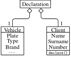
EXAMPLE.– Let us consider the class diagram of our accident declaration example, shown in Figure 2.2. A vehicle has several associated attributes, such as its license plate number, its type, and its brand. Similarly, a client has a name, a surname, and an insurance number. The client can execute adeclare()operation, in order to declare an accident. A declaration concerns exactly one vehicle and one client.
Declaration
Vehicle Plate Type Brand
. . .
Client Name Surname
Number declare()
1 1
Figure 2.2.Class diagram
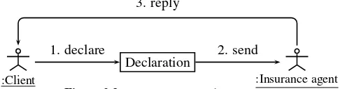
EXAMPLE.– The communication diagram in Figure 2.3 shows that the client should declare an accident by sending a messagedeclare. He can thensendthe declaration to the insurance agent who makes a decision in order toreplyto the client.
:Client
Declaration
:Insurance agent
1. declare 2. send
3. reply
Figure 2.3.Communication diagram
This information can also be represented bysequence diagrams, which, in addi-tion, show how objects are created.
EXAMPLE.– The sequence diagram in Figure 2.4 indicates message exchanges be-tween the different objects. Note that the operation initiated by the client to declare an accident also generates a declaration object.
client
:Declaration
insurance agent
declare
send
reply
Figure 2.4.Sequence diagram
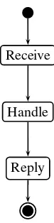
The flow of information in the system is represented by anactivity diagram, which gives additional information complementary to those of the communication and se-quence diagrams. It depicts the system evolution as seen by one of its actors.
EXAMPLE.– From the insurance agent point of view, the activities take place as pic-tured in Figure 2.5: he receives a declaration, handles it, and then sends his reply to the client.
Receive
Handle
Reply
Figure 2.5.Activity diagram – the insurance agent viewpoint
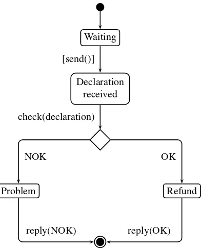
EXAMPLE.– The state diagram for our accident declaration example is shown in Fig-ure 2.6. The insurance agent initially waits. When he receives a declaration, he moves to a new state in which he is ready to handle it. After checking the declaration, two cases may occur: either there is no problem (OK) and the reimbursement can take place (a positive response is sent to the client), or there is a problem (NOK) and the insurance agent sends a negative response to the client.
Software tools enable a complex specification to be built. They check the consis-tency among the different diagrams. Moreover, they propose automatic generation of code and test scenarios.
Some diagrams, other than those mentioned in this section, exist, but their presen-tation is outside the scope of this book. For further information, see e.g. [PIL 05].
To conclude, semi-formal techniques such asUMLenable the characteristics of the system to be studied in depth during modeling, with a high level of abstraction, and the implementation detail can be addressed. The diagrams thus obtained provide a good view of the different aspects of the system. However, even though these diagrams are easy to understand for a non-specialist, grasping the full picture can be a challenge. Moreover, system validation cannot be exhaustive. Therefore, formal models aim to tackle these problems.
2.3. Formal models
Waiting
Declaration received
Problem Refund
[send()]
check(declaration)
NOK OK
reply(NOK) reply(OK)
Figure 2.6.State diagram for the insurance agent
In addition to the advantages of the previous techniques, formal models offer anal-ysis tools for the system under study:
– simulation provides evidence of the correct behavior or eventually errors to be discovered, especially severe ones. Correction at this stage is relatively cheap, com-pared to the correction of an already existing system, either implemented as software or hardware;
– exhaustive verification of system behavior can be performed. First, simulation is applied, leading to a coarse-grained debugging, and then the model is refined by verification of its expected properties.
2.3.1. Algebraic specifications
Algebraic specifications historically originate from data abstraction (“abstract data types”), and are the origin of object-oriented programming languages (see the class concept). They were further developed and enhanced to become formal specifications of the functional requirements for software modular design. Following the design of numerous algebraic specification languages, CASL(common algebraic specification language) was developed in the context of the CoFI international project (Common Framework Initiative for algebraic specification and development). This language is based on a careful selection of already explored constructs, such as sub-sorts, partial functions, first-order logics, structured and architectural specifications [AST 02]. The CoFI project website [COF11] contains the documents produced within the project, the language is described in a user manual [BID 04], and the reference manual [CoF 04] provides the complete formal semantics.
A CASL specification may include declaration for types, operations, and predi-cates (together with their arity), as well as axioms, which are first-order formulae. Some operations are considered as generators (or constructors) and are part of the type declaration (“datatype declaration”). A simple specification is described as follows:
spec NOMSPEC=
type type_name ::=gen_name(args)|. . . op op_name :op_args→op_res . . .
pred pred_name:pred_arg . . .
axioms %%first-order formulae end
The language includes constructs for modular design of specifications: unionandand thenextensions can be used for specification structuring.
spec NOMSPEC= SP1 and. . .andSPj then type type_name ::=gen_name(args)|. . .
EXAMPLE.– Let us consider the example from section 2.2. An accident declaration specification imports the modules specifying vehicles and clients.
spec DECLARATION = VEHICLEandCLIENTthen type Declaration::=. . .
end
spec NOMSPEC=
type type_name ::=gen_name(args)|. . .
op op_name :op_args→?op_res %%partial operation . . .
axioms
def op_name(args)⇔. . .
Thefreeconstruct forces the use of the initial semantics, avoiding explicit negation. Indeed, in thefreespecification models, term values are distinct unless their equality follows from the specification axioms [BID 04].
spec NOMSPEC= SP1 and. . .andSPj then
free { type type_name::=gen_name(args)|. . . op op_name :op_args→?op_res. . .
axioms . . .}
EXAMPLE.– A counter modulo3, using increments by1and by2as operations (see example in section 2.3.2) can be specified as follows:
spec COUNTER =
free { type Counter ::=0 |suc(Counter);
%% suc adds one
axioms suc(suc(suc(0))) =0;
op add2 :Counter→Counter
axioms add2(0) =suc(suc(0)); add2(suc(0)) =0;
add2(suc(suc(0))) =suc(0);} end
Generic specifications are most useful for reuse purposes. Specifying their parame-ters is simple, and an instance of the generic specification is obtained by providing a specification argument for each parameter. The specification below is an extension of the generic specification SET[ELEM] instance by INT (these specifications are part of the basic library [ROG 04]):
specNOMSPEC= SET [INT] . . .then. . .
Note that algebraic specifications include the properties as axioms. Hence, theo-rems having some impact on these properties can be proven.
2.3.2. Automata
Automataexplicitly describe the possible states of the system. Different kinds of automata exist (communicating automata, timed automata, with variables, etc.), each with specific characteristics.
An automaton can be illustrated using a graph where states of the system are nodes. The evolution from one state to another is performed byfiring a transition, represented on the graph by an arc linking the two states. The choice of which transition to fire is non-deterministic as several transitions may be fired from a single state. This enables different evolutions of the system to be represented.
(0,0)
(1,0) (0,1)
(2,0) (1,1) (0,2)
(2,1) (1,2)
(2,2)
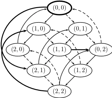
Figure 2.7.Automaton representing a system with2counters
EXAMPLE.– Let us consider a system with two counters modulo3, i.e. taking the following values successively: 0,1,2,0, etc. The two counters can either evolve in-dependently, by incrementing their value, or together when they have the same value. In this latter case (and this example), the first counter is incremented by2while the second is only incremented by1. This example is modeled by the automaton in Fig-ure 2.7.
In this description, the name of states contains the value of both counters, i.e.(0,2)
2.3.3. Petri Nets
Petri nets[GIR 03, DIA 09] are another formalism giving a view of both states and transitions of the system. The corresponding graph contains two types of nodes: places (represented by circles or ellipses) and transitions(rectangles). Places rep-resent part of the system state. They containtokens, which indicate the number of occurrences of this particular sub-state. As for automata, transitions represent events that can occur. The arcs entering a transition indicate thepre-conditionsrequired to enable transition firing, i.e. the conditions that must be satisfied for the action to occur. Similarly, the output arcs of the transition indicate itspost-condition, i.e. the result of the firing. Thefiring semantics for a transitiont thus consists of deleting the input tokens oft, as specified by the pre-conditions, and adding the tokens in the output places of transitiont, as specified by the post-conditions.
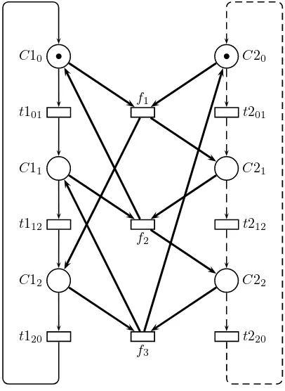
EXAMPLE.– The Petri net in Figure 2.8 models our counters system example.
C10
C11
C12
C20
C21
C22 t101
t112
t120
t201
t212
t220 f1
f2
f3
Figure 2.8.Petri net representing a system with2counters
andC12) indicate the different values the first counter can take, while those on the right hand-side (C20,C21, andC22) correspond to the values of the second counter. Similarly, transitions on the left-hand side (t101,t112, and t120) correspond to the increment of the first counter, and transitions on the right-hand side (t201,t212, and t220) correspond to the increment of the second counter. Transitions in the center of the figure (f1,f2, andf3) represent actions that increment the first counter by2and the second by1. Note that these transitions can only be fired when all their preconditions are satisfied, i.e. when both counters have the same value. The initial state of the system is represented by the distribution of tokens among places: both counters have value0.
The behavior of Petri nets is often analyzed through itsreachability graphorstate space. This graph shows an exhaustive representation of all states the system can reach. Starting from the initial state, all possible transition firings are examined, the resulting markings are added as nodes of the reachability graph, and transitions label the arcs between states, thus explicitly showing how one state is obtained from another. The state space of the Petri net in Figure 2.8 is similar to the automaton in Figure 2.7 (up to the arc labels not present in the automaton), where a marking(C1x, C2y)is represented by the pair(x, y).
As systems are becoming larger and larger, Petri net models have evolved towards high-level nets[JEN 91], in which the flow is captured by a Petri net structure, and data are explicitly represented using a data specification language. This language can either be dedicated to the kind of model [AMI11], a programming language [CPN11], or an abstract data type specification [REI 91]. High-level nets are easily understood by those with a good programming experience.
In high-level nets, tokens carry data that may be tested or changed while firing a transition. To express data manipulation, the net arcs are labeled with terms specifying the required preconditions and values associated with the created tokens.
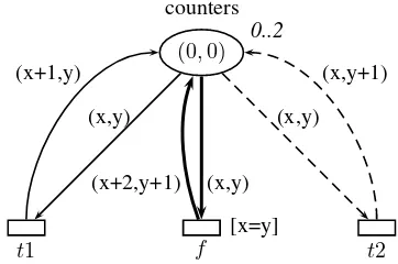
EXAMPLE.– Figure 2.9 presents a high-level net model of the counters system. The net has a single place that always contains a unique token. The token value is
(0,0)
counters 0..2
t1 f
[x=y]
t2
(x,y)
(x,y) (x,y) (x+1,y)
(x+2,y+1)
(x,y+1)
Figure 2.9.High-level net representing a system with two counters
2.3.4. Process algebras
Process algebrasare a family of mathematical formalisms with the aim of describ-ing concurrent systems. Numerous algebras have been defined, the two main families being those derived from CSP(communicating sequential processes [HOA 78]) and CCS(calculus of communicating systems[MIL 80]).
The most expressive process algebras often includeparameterized definitions, pro-cess expressions, andactions prefixes. The data manipulated can be simple values (CCS), structured events (CSP), or evennames(as in e.g.π-calculus [MIL 92]).
A process expression is generally built using the following operators1: –0is theinactive process;
–α.P is thesequential compositionof action prefixαfollowed by the expression of processP;
–PQrepresents theparallel compositionof processesPandQexpressions. The semantics considered is often aninterleaving semanticspossibly with a synchroniza-tion of processesPandQ. ProcessesP andQcoexist;
–P +Qis anon-deterministic choicebetween processesP andQ. Only one of them is executed;
– finally,A(v1, . . . , vn)represents a call to aparameterized definition. The elementaryactionsof processes are often limited to the following:
–τrepresents aninternal actionthat cannot be observed outside the process itself;
–c!v represents theemissionof a value v on namec, used as a communication channel. The c!prefix corresponds to an emission without value passing (as for a signal);
–c?(x) represents thereception of a name on a channelc. Variable xis then instantiated with the value received, for the sequel of the process. Reception without valuec?corresponds to an emission without valuec!;
–[a=b]tests theequalityof values or namesaandb; –[a=b]tests theinequalityof values or namesaandb;
–(νx)corresponds to theconstruction of private name x. This name is visible only for the process that created it. This construct is also calledrestriction.
EXAMPLE.– Let us consider a simplified machine delivering drinks. The commu-nication channels explicitly describe the interface between the machine and its user: channelcoinis used for inserting coins, and channelscoffee,tea, andwaterfor se-lecting a drink. A possible specification is the following:
⎡
⎣
Machine =coin?(p).([p= 1e]CoffeeTea+ [p= 50cts]Water) CoffeeTea =tea?.Machine+coffee?.Machine
Water =water?.Machine
The machine operates as follows. If the inserted coin is a1euro coin, the machine offers a choice (external choice, performed by the environment) between coffee and tea. If it is a50cent coin, only fresh water is proposed.
It is also possible to compose this machine with e.g. a client, so as to obtain a complete systemSys:
Client =coin!(1e).tea!.coin!(50cts).water!.0 Sys=ClientMachine
Here, a parallel composition of the client and the machine is used. The behavior of the client consists of first paying and then choosing tea, followed by paying and choosing water.
Process algebras admit many variants: timed, probabilistic, distributed, asynchronous algebras, etc.
2.4. After specification, verification
–automatic simulationis entirely performed using a computer tool. When a choice between transitions occurs, it is done in a non-deterministic fashion;
–guided or manual simulationsprovide the user with a choice either at each step or when several firings can occur. This allows the tool to be guided towards possible errors.
In any case, execution traces will be studied for coarse-grained checking of the behavior of the system for these particular executions. This also enables correction of major errors.
One of the main criteria to consider for simulation is the stop condition. It can be expressed according to:
– thenumber of firing stepsto execute during each simulation. The fixed limit should be large enough for the simulation result to be significant;
– aproperty that should not be satisfied. The goal is then to find an execution trace that violates a desired property. As soon as a state violating the property is found, the simulation terminates, and an inspection of its trace enables the source of the error to be determined.
This latter technique is close to verification issues. Verification techniques are applied as a second step, after simulation, in order to perform a more detailed anal-ysis of the system. Then, intended properties must be expressed using a formalism compatible with both the model and the chosen tool.
In order to check specific system properties, they must be written according to an appropriate formalism. Petri nets propose a set of “standard” properties, generic for any Petri net (boundedness, liveness, deadlocks, etc.). However, the properties of interest are often more complex and depend on the system under study (e.g. mutual exclusion between two processes). Such properties are then formalized using an ap-propriate language, such astemporal logics[BÉR 01a, CLA 00]. Temporal logics aim at expressing the sequentialisation of events. It is basically divided into two kinds of logics:
–LTL(linear time logic) expresses properties on execution paths;
–CTL(computation tree logic) expresses properties on the states encountered dur-ing the system evolution.
Verification of properties can be performed in different ways, as will be explained in part II:
–structural analysisis concerned with validation of intrinsic properties of the sys-tem, valid whatever the initial state;
Each of these techniques has its pros and cons. Making the appropriate choices from the start of the modeling phase is thus a key issue.
2.5. Outline of Part I
Formal models are key to the design and validation of secure and safe systems. For such an approach to be efficient, the system under study must first bespecified. This first step is of utmost importance since it has consequences on later stages of the process. The designer should consider many aspects of his system and answer questions that are not always obvious initially, so as to choose the most appropriate model or specification language. The expected properties that will be checked at a later stage must already be considered as well. Hence, the chosen abstraction level will allow these properties to be expressed without the burden of useless details. Once all these aspects have been considered, writing a specification using knowledge of the system is key to a successfulmodeling approach. This is detailed in Chapter 3.
For some systems, temporal or dynamic constraints should explicitly be consid-ered. Then, the use oftemporalorhybrid models will be privileged. They make it possible to verify not only the usual properties of untimed systems, but also real-time constraints. Thus, the duration of some events, the occurrence of a particular event before a time delay elapses, etc., can be checked. Time can be modeled using a global clock, i.e. shared by all components of the system, a local clock for each component, chronometers, etc. Adapted verification techniques are applied to these kinds of mod-els. These models and their associated verification techniques constitute the subject of Chapter 4.
When dealing with real systems, models are usually too large to be dealt with and to guarantee complete understanding, follow-up, and analysis. Moreover, parts of such systems can be reused within other similar systems, or during maintenance, e.g. when replacing one subsystem with another. Some models, such as hierarchical high-level nets [JEN 92, JEN 09] or modular nets [CHR 00, KIN 09], include a mod-ular structure from the start. But, these concepts are extended further so as to harness heterogenity issues, hence allowing for the development by components, which may be heterogenous. Then, not only should the component be modeled – and its indi-vidual behavior checked, but its interface with other system components must also be detailed (input/output, connectors, etc.). ADLs follow such an approach. Chapter 5 presents formal ADLs, which aim to verify properties, and implementation ADLs, which enable real tools to be obtained from their specification.
2.6. Bibliography
[AST 01] ASTESIANOE., REGGIO G., “Labelled transition logic: an outline”, Acta Inf., vol. 37, 2001.
[AST 02] ASTESIANO E., BIDOIT M., KIRCHNER H., KRIEG-BRÜCKNERB., MOSSES P. D., SANNELLA D., TARLECKIA., “CASL: the common algebraic specification lan-guage”,Theoretical Comput. Sci., vol. 286, p. 153–196, 2002.
[BÉR 01a] BÉRARDB., BIDOITM., FINKELA., LAROUSSINIEF., PETITA., PETRUCCIL., SCHNOEBELENPH.,Systems and Software Verification. Model-checking Techniques and Tools, Springer, 2001.
[BER 01b] BERGSTRAJ. A., PONSEA., SMOLKA S. A., Handbook of Process Algebra, Elsevier Science, 2001.
[BID 04] BIDOITM., MOSSESP. D., CASLUser manual, LNCS 2900 (IFIP Series), Springer, 2004, with chapters by T. Mossakowski, D. Sannella, and A. Tarlecki.
[CHR 00] CHRISTENSENS., PETRUCCIL., “Modular analysis of Petri nets”, The Computer Journal, vol. 43, p. 224–242, 2000.
[CLA 00] CLARKEE. M., GRUMBERGO., PELEDD. A.,Model Checking, MIT Press, 2000. [CoF 04] COFI (THE COMMON FRAMEWORK INITIATIVE), CASL reference manual,
LNCS 2960 (IFIP Series), Springer, 2004.
[COF11] CoFI, http://www.cofi.info, February 2011.
[CPN11] CPN TOOLSHOMEPAGE, http://cpntools.org/, February 2011.
[D 09] DEPARTMENT OFCOMPUTERSCIENCE, DAIMI, Examples of industrial use of CP-nets, http://www.daimi.au.dk/CPnets/intro/example_indu.html, May 2009.
[DIA 09] DIAZM., Ed.,Petri Nets: Fundamental Models, Verification and Applications,
ISTE-[GIR 03] GIRAULTC., VALKR.,Petri Nets for Systems Engineering: a Guide to Modeling, Verification and Applications, Springer, 2003.
[HOA 78] HOAREC. A. R., “Communicating sequential processes”, Communications of the ACM, vol. 21, p. 666–677, 1978.
[JEN 91] JENSENK., ROZENBERGG.,High-level Petri Nets, Springer, 1991.
[JEN 92] JENSENK.,Coloured Petri Nets: Basic Concepts, Analysis Methods and Practical Use. Volume 1: Basic Concepts, Monographs in Theoretical Computer Science, Springer, 1992.
[JEN 09] JENSENK., KRISTENSENL.,Coloured Petri nets: modelling and validation of con-current systems, Monographs in Theoretical Computer Science, Springer, 2009.
[JØR 04] JØRGENSENJ., BOSSENC., “Executable use cases: requirements for a pervasive health care system”,IEEE Software, vol. 21, p. 34–41, 2004.
[KIN 09] KINDLERE., PETRUCCIL., “Towards a standard for modular Petri nets: a formal-isation”, Proc. 30th Int. Conf. Application and Theory of Petri Nets and Other Models of Concurrency (PetriNets’2009), vol. 5606 ofLNCS, Springer, p. 43–62, 2009.
[MED 00] MEDVIDOVICN., TAYLORR. N., “A classification and comparison framework for software architecture languages”, IEEE Transactions on Software Engineering, vol. 147, p. 225–236, 2000.
[MIL 80] MILNERR., “A calculus of communicating systems”, vol. 92 ofLNCS, Springer, 1980.
[MIL 92] MILNERR., PARROWJ., WALKERD., “A calculus for mobile processes”, Infor-mation and Computation, vol. 100, p. 1–40, 1992.
[PET 03] PETRUCCIL., KRISTENSENL. M., BILLINGTONJ., QURESHIZ. H., “Developing a formal specification for the mission system of a maritime surveillance aircraft”, Proc. 3rd Int. Conf. on Application of Concurrency to System Design (ACSD’03), Guimarães, Portugal, June 2003, IEEE Comp. Soc. Press, p. 92–101, 2003.
[PIL 05] PILONED., PITMANN.,UML 2.0 in a Nutshell, O’Reilly, 2005.
[REG 03] REGGIOG., ASTESIANOE., CHOPPYC., CASL-LTL: A CASLextension for dy-namic reactive systems, version 1.0 – Summary, Report num. DISI-TR-03-36, University of Genova, 2003.
[REI 91] REISIGW., “Petri nets and algebraic specifications”,Theoretical Computer Science, vol. 80, p. 1–34, 1991.
Specification and Design Approaches
3.1. Introduction
The aim of this chapter is to describe how to write a consistent system specifica-tion. The question under study here is the following: “how do you write and develop a specification?” It is obvious that before starting to write the specification of a com-plex problem, the problem should be studied, structured, and split into parts, using processes that will be detailed at a later stage. Moreover, appropriate choices should be made at an early stage so that the specification reflects the important characteristics of the system for which some properties must be guaranteed. The choice of an ap-propriate modeling language and associated verification techniques, within the large existing zoo, is thus a major issue.
Therefore, section 3.2 presents criteria that should be taken into account for the specification to fulfill its intended objectives. Thus, before even starting to write the specification, the important characteristics of the specification should be carefully considered, i.e. which modeling language should be chosen, which abstraction level should be selected, the expected properties that should ultimately be verified.
Then, section 3.3 introduces a modeling methodology. Such an approach helps the designer to choose the constituent features of the system to model, as well as the relevant actions. It helps him in formalizing the essence of the relations between these and constructing a formal model step by step, starting from an informal description.
3.2. Criteria for developing specifications
It is necessary, before starting the development of a specification, to consider the important characteristics of the system under study. Such an approach enables an appropriate formalism to be chosen with respect to the system, and also enables the model to be structured, so that it will be easier, at a later stage, to enrich the model by incorporating additional details. Finally, the formalism used must provide analysis techniques for the intended properties.
In this section, we describe the different aspects to be considered before starting to write the system specification. Then, a rather simple case study illustrates this approach.
3.2.1. Relevant concepts
The first step identifies therelevant conceptsin the system under study. The key elements constituting the system are exhibited, thus guiding the choice for a formal-ism.
System data types More or less complexdatacan appear in the system under study. Hence, it is important to determine whether details for these data are necessary or not. Indeed, in general, the higher the description level, the less efficient the associated verification techniques are.
EXAMPLE.– Let us consider a communication protocol, with a special focus on the adequate functioning of retransmissions with this protocol. The detail of the message content is not necessary, whereas the kind of messages exchanged may very well be. Then messages can be modeled using solely their type (request, indication, response, confirm) and their sequence number.
When handling complex data that should explicitly be modeled, the choice of for-malism is preferably high-level models, such as abstract data types or colored Petri nets. Conversely, if the actual data are not that important, but only their availability is required for the system to operate, lower-level formalisms, such as automata or Petri nets will be preferred. In an intermediate case, where few simple types are used and can be mapped to integers or enumerations, counter automata or symmetric Petri nets1
are more appropriate.
Time Among critical systems are real-time systems, which includetemporal con-straints of different types such as:
– awaiting time, such as a timeout;
– an actionexecution time, such as the movement of a robot.
Several extensions of automata and Petri nets include time. They will be detailed in Chapter 4. Two main paradigms are used when considering time. Some formalisms assume aglobal clockexists, which is used by all operations with timing constraints. Others consider there is no such global clock and operations can occur within a time interval from the moment all their preconditions are satisfied; or each of the different system components have their ownlocal clock.
Time can be modeled along two main trends:
–discrete timecorresponds to the observation of the system at regular clock ticks, or to a sampling;
–continuous time reflects the evolution of the system without considering time slices. This is particularly relevant when studyinghybrid systemswhere variables val-ues may evolve according to time (for example, acceleration, change in temperature, etc.).
It is not always necessary to take time into account in the specification. Indeed, this is the case when the focus of interest isqualitative properties, in which time is not considered.
Determining whether time should be considered in the specification is hence an issue. Moreover, if it is the case, the nature of time, i.e. discrete or continuous, and which clocks (local, global, time intervals) are chosen is in accordance with the prob-lem studied.
The choice between thesynchronousorasynchronousmodel paradigm [LYN 96] will also have to be carefully considered. Subsystems of a synchronous model evolve at the same rate, whereas in an asynchronous model, one subsystem may progress while another waits for a particular event to happen.
Communication Complex systems are generally composed of communicating sub-systems. Communications may take different forms:
–rendez-vousenforces asynchronizationbetween the different participating en-tities. A subsystem sends a message that is received simultaneously by one or more other subsystems. If one of these is not yet ready to synchronize, the other subsystems have to wait. This kind of communication is explicitly modeled in communicating automata and in Petri nets.
eventuallylose messagesor bereliable. Queuing automataand high-level Petri nets provide such modeling mechanisms.
3.2.2. Abstraction level
Writing a specification is definitely not a one-shot process. A major notion in this process is theabstraction level. The modeling starts at a very abstract level, before applyingincremental constructionthrough severalrefinementsteps. At each step, the model should be analyzed and proven correct before the next refinement. Refining consists of considering more elaborate data structures so as to consider additional details, but also to augment the automaton or Petri net structure, in order to elicit a complex action by breaking it down into several more elementary actions.
Thus, such a specification approach starts with a rather abstract model, where only the key aspects of the system are modeled, and sequentially adds more and more details.
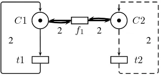
EXAMPLE.– Let us consider again the example of the modulo-3counters introduced in section 2.3.2. Even though this example is extremely simple, it could be seen as a system with two counters and two kinds of operations: incrementing a single counter by one unit and incrementing both counters, the first one by2and the second by1. This leads to the model in Figure 3.1. This model can then be refined into the one in Figure 2.8.
C1 C2
t1 t2
f1
2 2
2 2
Figure 3.1.Abstract Petri net for a system with2counters
Choosing an adequate abstraction level is all the more important as taking into account unnecessary details complicates the analysis of the system.
3.2.3. Specification structuring
Since writing a complex system specification is a multistep process, structuring mechanisms are necessary. Such a system is usually composed of several interacting subsystems. An interesting approach is to specify each of these subsystems in isola-tion, and then specify their interactions. Such an approach has several advantages:
– the design of each subsystem focuses on its own behavior. Hence, the designer is not bothered with other subsystem specifics;
– a subsystem may allow for different variants. The whole system can then be analyzed with these different possibilities, only replacing one model of the subsystem by another within the complete model;
– similarly, a component (or subsystem) designed for a particular problem may be reused within another complex system. Therefore, it is not necessary to model this component again;
– severalinstancesof a same component may be integrated in the model, using parameterized modeling features, so as to clearly identify each individual instance during the analysis phase. Hence the subsystem model is not duplicated;
– This approach enables generic components or subsystems to be used, which are available in libraries of frequently used components, with as little adaptation as possi-ble.
EXAMPLE.– Consider the specification of a communication protocol. Such a system usually involvessenderandreceiverprocesses, as well as acommunication medium. These three components can be specified independently of each other. It may be of particular interest to e.g. model two kinds of senders, and verify the characteristics of the protocol with each of these.
Some specification formalisms include structuring concepts, either intrinsic or in-tegrated. This is the case for hierarchical colored Petri nets [JEN 92, JEN 09], in which the model architecture follows a tree-like structure. The highest level (tree root) cor-responds to the most abstract description of the system, while the lowest levels (tree leaves) describe the different elements in great detail.
3.2.4. Properties
3.2.5. Future evolution of model and properties
Both the system and properties specifications are deemed to evolve during the design and verification phases. This aspect must also be taken into account, in order to guarantee that the intended abstraction level is reached.
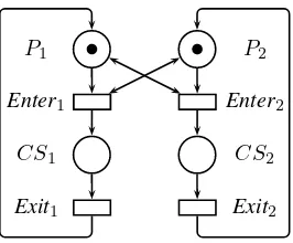
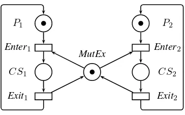
EXAMPLE.– The Petri nets in Figures 3.2, 3.3, 3.4 and 3.5 all model the problem of mutual exclusion between two processes, competing for access to a critical section.
These models comprise a loop to represent a process behavior: it is initially not in the critical section (placeP), it can ask to enter the critical section (transitionEnter),
after which it is in the critical section (placeCS), which it can leave (transitionEnd)
to return to its initial state. At any time, only a single process can be in the critical section. As a consequence, the right for a process to enter the critical section is pre-conditioned by the status of the other process, which should not be in the critical section itself. This is modeled by the double arcs (i.e. arcs with two arrow heads) in Figure 3.2. A standard way of handling the access to the critical section is to grant some “access right”, modeled by a token in placeMutExin all other Petri nets presented for this problem. In Figure 3.3, the loop is explicitly shown for each process, whereas in Figure 3.4, both cycles are superposed and the two processes specified by two tokens in placeP. Figure 3.5 is similar, using a colored Petri net that enables the
two processes to be distinguished by naming themp1andp2.
P1
CS1
P2
CS2 Enter1
Exit1
Enter2
Exit2
Figure 3.2.Mutual exclusion between two processes (version 1)
P1
CS1
MutEx
P2
CS2 Enter1
Exit1
Enter2
Exit2
Figure 3.3.Mutual exclusion between two processes (version 2)
P
CS
MutEx Enter
Exit
Figure 3.4.Mutual exclusion between two processes (version 3)
Now, assume that the internal behavior of the critical section for each process has to be detailed. Only the Petri net in Figure 3.5 enables the different processes involved to be distinguished while maintaining a relatively compact model (the net in Figure 3.3 also distinguishes the process identities).
Similarly, if verifying that a process can enter the critical section, whatever its identity, nets in Figures 3.3 and 3.5 are more appropriate. Hence, this shows that even for a very simple example, the design choices must definitely take into account future evolutions of the model as well as checking the properties.
3.2.6. Using specification and verification tools
P p1+p2 {p1,p2}
CS {p1,p2} MutEx
e {e} Enter
p
e p
Exit
p e
p
Figure 3.5.Mutual exclusion between two processes (version 4)
to describe these models in order to exchange them between different software tools, and thus take advantage of the particular analysis techniques they implement. A com-panion framework to the standard [HIL 10] is provided to ease the implementation of writing and reading such standardized Petri nets files.
3.2.7. Case study: modeling a railway system
In this section, we consider the more complex design example of a model railway. This example is taken from a students’ project [BER 01] with the aim of formally designing and analyzing an electrical model railway before implementing it on the actual hardware. It is thus mandatory to ensure that no collision will occur before the final solution is tested on the real devices.
The physical layout of the railway track is presented in Figure 3.6. It is composed of approximately15m of track divided into16sections (blocks B1 to B16), plus two garage side tracks (ST1 and ST2). These are connected with four switches and one crossing. The hardware allows for several trains to circulate simultaneously. It is connected to a computer, which sends information on the tracks and transmits orders to trains (stop, advance, go backwards) and also to switches. Each track section is equipped at both ends with a sensor to detect that a train is entering or leaving the section.
switch 1 switch 4
Figure 3.6.Setup of the model railway track
section color section = union t:train + none;
t13