BIM-BASED INDOOR PATH PLANNING CONSIDERING OBSTACLES
Man Xu a, b,c,d , Shuangfeng Weia, b,c,d,*, Sisi Zlatanova e, Ruiju Zhanga, b,c,d
a School of Geomatics and Urban Spatial Information, Beijing University of Civil Engineering and Architecture, Beijing, China -
b Beijing Key Laboratory For Architectural Heritage Fine Reconstruction & Health Monitoring,Beijing,China - [email protected] c Key Laboratory for Urban Geomatics of National Administration of Surveying, Mapping and Geoinformation, Beijing, China
d Engineering Research Center of Representative Building and Architectural Heritage Database, the Ministry of Education,Beijing,China -
e 3D Geoinformation, Department of Urbanism, Faculty of Architecture and The Built Environment, Delft University of Technology,
Delft, The Netherlands - [email protected]
Commission IV, WG IV/5
KEYWORDS: BIM, IFC, Obstacles, Indoor Navigation, Space Subdivision, Path Planning
ABSTRACT:
At present, 87% of people’s activities are in indoor environment; indoor navigation has become a research issue. As the building structures for people’s daily life are more and more complex, many obstacles influence humans’ moving. Therefore it is essential to provide an accurate and efficient indoor path planning. Nowadays there are many challenges and problems in indoor navigation. Most existing path planning approaches are based on 2D plans, pay more attention to the geometric configuration of indoor space, often ignore rich semantic information of building components, and mostly consider simple indoor layout without taking into account the furniture. Addressing the above shortcomings, this paper uses BIM (IFC) as the input data and concentrates on indoor navigation considering obstacles in the multi-floor buildings. After geometric and semantic information are extracted, 2D and 3D space subdivision methods are adopted to build the indoor navigation network and to realize a path planning that avoids obstacles. The 3D space subdivision is based on triangular prism. The two approaches are verified by the experiments.
*Corresponding author
1. INTRODUCTION
Indoor navigation refers to finding a path from current location to the destination when moving in a building. It is inevitable to encounter some obstacles when moving, therefore it is critical to avoid these obstacles effectively. Most of the reported research focuses on building the path from 2D plan, as commonly obstacles are ignored (Thill et al., 2011). Generally, obstacles affect the path planning and make it more complicated. There are fixed furniture or equipment facilities in indoor environment, but also some movable obstacles such as chairs and tables. All these are non-navigable spaces and they are classified as NonNavigableSpace in the OGC standard-IndoorGML, but their characteristics are not considered in detail (Wei, 2016). IndoorGML is OGC standard for representation and exchange of indoor navigation models (geometry and network). It provides a framework to represent indoor spaces and their topology (connectivity), which are needed for the components of navigation networks. It is seen as a complementary standard to CityGML and IFC. In some cases information about the types of obstacles are required duality (Lee et al 2014).
As frequently discussed in the literature, 2D path planning cannot meet entirely the requirements for different forms of locomotion modes such as walk, drive and fly. There is an increased interest in pathfinding in 3D space. As a result, refined indoor models e.g. BIM and CityGML LoD4 are investigated for path planning. Extraction of building geometric information have been completed in most studies, but some
properties of entities and the semantic information between them have been lost, which are critical in the navigation (Teo and Cho, 2016; Hamieh, 2017; Brown, 2013). Research have already shown that semantic, topology and other information helps improve the accuracy of navigation. Industry Foundation Classes (IFC) contains a large number of geometric and semantic information as BIM's data conversion standard (Lin et al., 2013), which is especially suitable for 3D indoor path planning. CityGML LoD4 also contains a lot of indoor geometry and semantic information, but the indoor information is limited compared to IFC (Wei, 2016). The navigation path can be made more rational and user-adaptable based on IFC (Teo and Cho, 2016; Hamieh, 2017). Therefore, we concentrate on 3D indoor path planning based on IFC which takes into account obstacles.
This paper focuses on multi-floor building and obstacles, using IFC as data source. 2D and 3D space subdivision are used to build the indoor navigation network. After dealing with the single floor, multi-floor are connected through staircase or elevator. Finally, the Dijkstra algorithm is used for path planning avoiding the obstacle.
2. RELATED WORK
IFC is widely used as the source data for indoor space model (Taneja et al., 2011; Isikdag et al.,2013; Boysen et al., 2014). Teo and Cho(2016) also consider IFC, from which useful information is integrated into their models to allow indoor and outdoor path planning applying Entrnce2Street strategy. Hamieh (2017) proposes to use the BIM model for indoor path planning, in which the paths within the spaces are possibly refined, depending on their contents, such as moving objects or real-time spatial state.
BIM has been used as a basic model for emergency situations, which requires a real-time indoor high-quality model expression for automated generation of variable density navigable networks environment (Boguslawski, 2016). Li et al.(2014) introduce a novel positioning algorithm for an emergency scene of building fire. The algorithm based on BIM model obtains the geometric position of indoor sensor, so as to quickly and accurately determine the position of the rescuer and the injured. Boguslawski et al.(2016) propose a construction of variable density navigation networks based on a 3D topology model, which mainly used in emergency escape. Li et al.(2015) propose an effective method for extracting the detailed semantic semantics, functional information and interrelated information of BIM model (Li et al., 2015). Brown et al.(2013) suggest topological space information still should be integrated in the indoor navigation, although collection and processing of sensor information, and positioning algorithms have developed rapidly. It describes these requirements and build 3D topological space model based on them. Boguslawski et al.(2015) describe complex indoor situations combining BIM and GIS to automatically generate navigation models rather than simply describing 3D indoor scenes. The dual graph is constructed representing relationship between rooms after 3D model is reconstructed.
Most of these approaches, however, consider the spaces free of obstacles. Generally, the granularity of the semantic models is kept relatively coarse. Zlatanova et al.(2014) discuss space division in 2D and 3D space from two aspects: partial division or complete division, generation of network or grid. Detailed partition of a room is rarely considered. Goetz and Zipf(2011) consider fixed obstacles, and manually add a visual point combinatorial map as a data structure. To avoid complexity of 3D representations, Lin et al.(2013) propose to map the entities of 3D space onto 2D plane. It takes obstacles into account and discretization and meshing 2D plane, but it ignores the fact that the UAV can fly over obstacles. Diakité and Zlatanova(2016)propose a novel method using G-maps to generate valid indoor spaces in IFC models, though IfcSpace objects in IFC models sometimes contain wrong geometric and topological description. Xiong et al. (2016) propose a method to extract indoor free space with voxels with variable size. The efficiency of the method depends on the voxels unit length, that is, the more voxels, the higher precision and consequent larger amount of data. Rodenberg et al.(2016) discuss a path computation based on octree subdivision of space.
Free scape subdivision into regular or irregular cells has follow a novel approach for space subdivision, which is based on triangular prism. Triangular prism’s size is variable and
depends on the bounding objects, which allows for more accurate path computation. Triangular prisms has been used as body elements to achieve 3D geological modeling and visualization. It allows to accurately represent the boundary area and do not generate redundancy like when using tetrahedrons (Cheng et al., 2004; Meng et al., 2010). Commonly geological phenomena are irregular and the triangular prism can have large variety. In contracts, indoor space exhibit a high level of parallelism (ceilings are parallel to floors), which allows for some simplifications.
Once the free space is identified, a connectivity network has to be built to run path computation algorithms. Most of the existing methods for extracting the path network are based on medial Axis Transformation (MAT) and Visibility Graph (VG) (Yang and Worboys, 2015). Straight-Medial Axis Transformation (S-MAT) is proposed by Eppstein and Erickson(1999) and it results to be a good representation of natural human behaviour, though, it may not represent accessibility within buildings accurately (Mortari et al, 2013). In open space, it is obviously the weakness of S-MAT that the generated path is distort. Taneja et al.(2011) extract useful semantic information from the IFC file and obtained the Geometric Topology Network (GTN) based on the geometric topology network using S-MAT and improved MAT algorithm. Tang et al.(2015) propose a new idea to solve the topology construction, which removes the semantic information from the IFC file, extracting navigable space, e.g. corridor, mapping above elements to the 2D plane, and reconstructing Topology networks using S-MAT. Liu and Zlatanova(2011) propose the ‘door-to-door’ approach based on Visibility Graph, which derives the connections between doors, which are used to create the network for navigation. This network adapts better to the walking behaviour of pedestrians. However, the main problem of VG is that the rapid increase in the number of edges will lead to complicated interpretation of route for pedestrians. Chen and Huang(2015) propose a combination of MAT and VG(A-MAT-VG), in which geometric information is retrieved from BIM model to build the graph to find the path. Risks based on building materials and traffic of pedestrians are to be adapted for network edge costs to ensure the lowest cost.A-MAT-VG can reduce the execution time of path analysis and to reserve accuracy close to the VG approach. This paper proposes an indoor navigation approach that considers obstacles in 3D space, reads the geometric and semantic information of entities such as obstacles and space in the building from IFC file through Autodesk Revit, subdivides 3D space with 2D grid and 3D space subdivision based on
triangular prism to build the indoor navigation network. The approach can be applied a 3D navigation in multi-storey environment. The remainder of this paper is organised as follows: Section 3 presents technical route of this approach. Section 4 presents the implementation and experiments and Section 5 concludes this paper and discusses the future work.
3. TECHNICAL WORKFLOW
elements, and the relationship between an element and the spatial structure (IfcRelContainedInSpatialStructure). Two specific space subdivision methods such as 2D grid subdivision and 3D space subdivision based on triangular prism are developed to build the indoor navigation network. In the first method, value 0 and 1 represents navigable and non-navigable area. In the second, IfcSpace as a unit is divided into smaller
areas, which are operated based on extracted geometric and semantic information. Consequently, a navigable network is created, selecting the regional feature points to build the navigation network, and finally with the single floor navigation graph, whole navigation graph of multi-floors are connected by staircase or elevators.
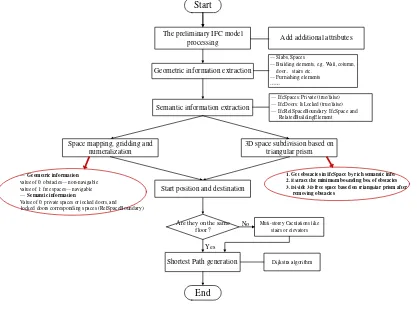
Geometric information extraction
— Slabs, Spaces
— Building elements, e.g. Wall, column, door, stairs etc.
—Furnishing elements
…… The preliminary IFC model
processing Start
Add additional attributes
Semantic information extraction
— IfcSpaces: Private (true/false) — IfcDoors: IsLocked (true/false) — IfcRelSpaceBoundary: IfcSpace and RelatedBuildingElement
Space mapping, gridding and numeralization
3D space subdivision based on triangular prism
— Geometric information value of 0: obstacles— non-navigable value of 1: free spaces— navigable — Semantic information
Value of 0: private spaces or locked doors, and
locked doors corresponding spaces (RelSpaceBoundary)
1. Get obstacles in IfcSpace by rich semantic info. 2. Extract the minimum bounding box of obstacles 3. Divide 3D free space based on triangular prism after removing obstacles
Start position and destination
Shortest Path generation
Are they on the same floor?
Yes
Muti-storey Caculations like stairs or elevators
No
Dijkstra algorithm
End
Figure 1. Technical workflow
4. IMPLEMENTATION AND EXPERIMENTS
4.1 Experiment using 2D grid subdivision
Two types of buildings are used for the tests. Figure 2 shows the two buildings: two- and three-storey buildings containing walls, doors, windows, and furniture. The structural elements of building 1 are mostly on first floor, which helps to understand how the approach functions in a single storey. The second building is more complex and contains extra structural elements like columns, distribution, balconies, stairs, functional rooms and so on. The five steps to achieve a path for navigation are explained below:
Step 1: A new building template in Autodesk Revit is created and additional attribute information is added. On the first floor, there are two doors of whose property “IsLocked” is TRUE, so they are locked (Figure 4). The property “IsLocked” of other three doors is FALSE, so they are open. Similarly, add additional attributes Private with the same method to the space to represent the space private or not. A room in is not accessible and therefore it is market as Private (Figure 4).
Figure 2. IFC model for Building 1 (left) and Building 2 (right)
Figure 4. Single floor semantic information extraction in
Building 1(Unpassable area in black, passable area in white)
Step 2: The geometric information of building is extracted and processed to obtain GeometricSet information including floors, spaces, walls, pillars, doors, furniture, facilities, and stairway building elements. Some simple furniture is obtained by "SweptSolid", such as slabs, spaces, walls, and columns, while some complex elements are obtained as "B-rep".
Step 3: In addition to the attribute information (Step 1), the relationship information between entities is added. In the IFC syntax, it is reflected by IfcRelSpaceBoundary. The space related to doors A and B in Figure 12 is defined, and it is checked whether their properties “IsLocked” are true. In this case it indicates that the space is not accessible, because door B is closed, i.e. the “IfcRelSpaceBoundary-> non-navigable” (Figure 5).
Step 4: The range of the mesh is decided by the boundary of IfcSlab. Four sides of IfcSlab are divided by the same unit size, which is the grid size. All elements in one IfcSlab are mapped according to the grid range. All walls, doors, columns, furniture, and configuration are considered obstacles, and therefore the nodes representing them in 2D grid have value 0 (non-navigable) by automatically identified. After mapping the geometric information, each grid is assigned a number attribute and navigable value. If it is determined that there are open
doors, the navigable value is 1, otherwise it is changed to 0. The geometric information of all obstacles mainly includes boundary information, which can be mapped to 2D. Nodes within the range have the same value with the boundary nodes. We use different grid size N. Grid with N = 50 is shown in Figure12. The left blue box indicates private space corresponding grid value is 0, and the right blue box indicates that derived unnavigable spaces by IfcRelSpaceBoundary, whose grid value is changed to 0. The red box represents the doors of Islocked = true / false. As mentioned previously value 0 indicates a non-accessible area, and 1 represents a navigable area.
Figure 5. Mapping of geometric and semantic information
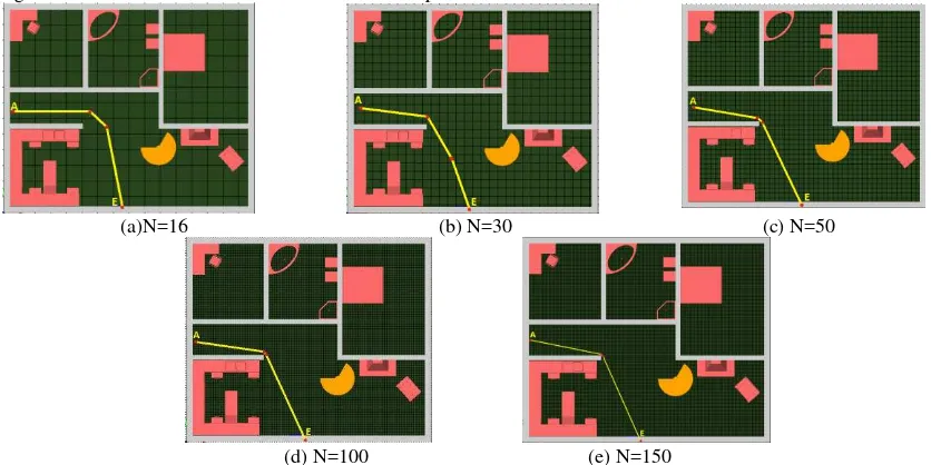
Step 5: The last step is computation of the navigation path. If the path between navigable points passes through non-navigable points (node value is 0 in Figure 5), the line segment is ignored. When the connectivity network is established, the Dijkstra algorithm is used to calculate the shortest path. Step 2 to step 5 are automated processed. We discuss an example for finding the path between door E and door A (Figure 6). In Figure 13, (a) (b) (c) (d) (e) respectively shows the path when N = 16, 30, 50, 100, 150.
(a)N=16 (b) N=30 (c) N=50
(d) N=100 (e) N=150
Figure 6. The shortest path for different grid count and size
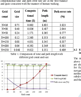
We analyze the calculation time and the length of path when N value is different. The comparison results are shown in Table 1. Clearly it can be seen that the larger the N value is, the more accurate the calculated path will be. The path computed with the largest value tends to represent the true path (due to the path length gradually close to the line in Figure 6, which we use as the real value as a reference), and the error rate gradually decreases. It also shows that as the N value increases, the grid size becomes smaller, resulting in higher computational time
habit of human walking. In summary, when N is about 42, the computational time and path error rate are in the best balance and quite consistent with the manner of human walking.
Grid count
Grid size
Computa tional time (S)
Path length
(m)
Path error rate (%)
N=16 0.75 0.002 8.635 3.823
N=30 0.40 0.036 8.487 2.044
N=50 0.24 1.571 8.365 0.577
N=100 0.12 2.363 8.353 0.433
N=150 0.08 4.031 8.345 0.337
N=200 0.06 6.392 8.349 0.385
N=250 0.048 9.022 8.351 0.409
Table 1. Comparison of time and path length with different grid count and size
Figure 7. Comparison of computational time, path length and error with different grid count
(a) (b)
Figure 8. The shortest paths from point E to point F (left) and from point F to point G (right)
Figure 8(a) shows that the path bypasses the obstacles to reach point F from point E. There are three turning points in this path. Figure 8 (b) illustrates the path from F to G, which passes through five turning points, smoothly avoiding obstacles. It demonstrates that the approach can deal with obstacles (including doors, furniture, etc.) correctly, and get the shortest path with Dijkstra algorithm.
We have described in detail how to deal with a single-layer in IFC model taking into account the obstacles. The shortest path between any two points can be found for each grid layer. The path across multi-floors of Building 2 can be obtained in similar way, considering each floor individually. Figure 9 shows the final result of path computation.
Figure 9. Paths in multi-floors
4.2 Experiment on 3D spatial subdivision method for indoor navigation
The method presented above does not consider the spaces above obstacles, i.e. only the spaces for of walking or driving are identified. However a complete 3D subdivision is needed for flying or for considering the size of the agent to be navigated. For such cases we apply a 3D space subdivision method based on triangular prisms. The steps resemble the 2D subdivision in a way, but more attention is paid on the IfcSpace and the relationships with the furniture.
Figure 10. IfcSpace containing furniture
(1) The relationship between furniture and ifcSpace can be found by IfcRelContainedInSpatialStructure, It is calculated that the bounding box of the obstacle and free space over the obstacle in the same vertical range;
(2) The 3D space subdivision method based on triangular prisms is used to divide the space of which the obstacles are removed (Figure 11). Taking into account that triangulation can accurately preserve the shape of the obstacles (Xu et al 2016), we give preferences to such an irregular subdivision also in the 3D case. Regular 3D grid subdivisions has shown to result in some level of generalisation (Xiong et al, 2016, Rodenberg et al, 2016). we use constrained Delaunay triangulation to subdivide the IfcSpace excluding obstacles on the ground with the same elevation. Then the triangles are stretched to the top surface of IfcSpace to constitute triangular prisms.
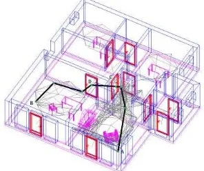
(3) Following the Poincare duality (Lee, J., Ki-J. Li, S. Zlatanova etc.2014), the center point of the subspaces are selected and connected to build the navigation network, which includes feature points of prisms and free space over the obstacles. Lines connecting these feature points indicate the edges of the navigation network. We chose to connect all the nodes excluding edges that cross the bounding box of the obstacles and free space over the obstacle in the same vertical range. If vertical range of the obstacle intersect with the lines of network nodes, the line should be ignored. After the subspaces navigation network is built, the gravity points of the bounding box of doors are connected to the closest feature point in the navigation network. In Figure 12, red represents the door, pink means furniture (obstacle), green represents the newly generated 3D TIN navigation network.
Figure 12. Resulting network for navigation in one IfcSpace
(4) Following (1), (2) and (3), the entire network in one IfcSpace can be created. Then, the neighbouring IfcSpaces are connected by doors, among which open free space is connected to other space through the center of its own. So the full navigation network of one building floor can be completely constructed.
(5) Finally, Dijkstra algorithm is used to calculate the shortest path. The shortest path from A to the B in the Floor 1 is shown in Figure 13, where there are four turning points and doors C and D between A and B.
Figure 13. The shortest path from A to B
5. CONCLUSION AND FUTURE WORK
This paper presents two approaches for path computation avoiding obstacles from BIM (IFC) models. Different from the traditional 2D data processing methods, IFC models can provide the needed information either as building components or their attribute for a multi-floor path computation. We have presented two approaches 2D grid and 3D triangular prism. 2D grid approach is quick way to provide a navigation, when 3D requirements are not of importance. The triangular prism-based 3D space subdivision method can be used to compute an indoor navigation path for unmanned aerial vehicles or other
equipment that can move in the air, which omit the process of mapping 3D space to 2D plane. Delaunay triangulation is commonly applied for quick subdivision of large spaces to construct a 3D triangular network, which is moved from the ground to the center point of triangular prisms.
There are still some limitations use of IFC for network creation. Firstly, the original IFC data may not be directly applicable for navigation, so we need to manually add some custom attributes. Alternatively, IFC file need to be created according to certain rules to contain all needed information. Secondly, as there is a certain error when mapping the 3D spaces to a 2D grid, it should be carefully considered what grid resolution should be used. In any case some level of generalisation of the obstacles takes place. Thirdly, in the grid and triangular space may take a lot of memory and slow down the computation process. Regarding the shortcomings mentioned above, a further study need to be carried in the future.
ACKNOWLEDGEMENTS
This work is supported by the National Natural Science Foundation of China (No. 41501495,No. 41601409), The Dutch project M4S 13742 Smart 3D indoor models to support crisis management in large public buildings (www.sims3d.net), The National Keypoint Research and Invention Program of the Thirteenth(No. 2016YFC0702107) and Beijing Natural Science Foundation(No.8142014, No.8172016).
REFERENCES
Boysen M, Haas C D, Lu H, et al, 2014. A Journey from IFC Files to Indoor Navigation. Web and Wireless Geographical Information Systems. pp.148-165.
Boguslawski P, Mahdjoubi L, Zverovich V, et al, 2015. Automated construction of variable density navigable networks in a 3D indoor environment for emergency response.
Automation in Construction, 2016, 72:115-128.
Boguslawski P, Mahdjoubi L, Zverovich V, et al, 2016. Two-Graph Building Interior Representation for Emergency Response Applications. ISPRS Ann. Photogramm. Remote Sens. Spatial Inf. Sci., Volume III-2, pp.9-14
Brown G, Nagel C, Zlatanova S, et al, 2013. Modelling 3D Topographic Space Against Indoor Navigation Requirements. Progress and New Trends in 3D Geoinformation Sciences.
Springer Berlin Heidelberg. pp.1-22.
Boguslawski P, Mahdjoubi L, Zverovich V, et al. 2015. BIM-GIS modelling in support of emergency response applications. Building Information Modelling.
Chen P G, Gong J Y, Shi W Z, et al, 2004. Geological Object Modeling Based on Quasi Tri-prism Volume and Its Application. Geomatics and Information Science of Wuhan University, 29(7), pp.602-607.
Chen A Y, Huang T 2015. Toward BIM-Enabled Decision Making for In-Building Response Missions. IEEE Transactions on Intelligent Transportation Systems, 16(5),pp.121-128.
Diakité., A. A., and S. Zlatanova, 2016, Valid Space Description in BIM for 3D Indoor Navigation, International Journal of 3-D Information Modeling, Vol 5(3), pp. 1-17
Ann. Photogramm. Remote Sens. Spatial Inf. Sci., IV-2/W1, 241-248
Eppstein, D. & Erickson, J., 1999. Raising Roofs, Crashing Cycles & Playing Pool: Applications of a Data Structure for Finding Pairwise Interactions. In: 14th Annual ACM Symposium on Computational Geometry, Minneapolis, USA, pp. 58-67.
General Administration of Quality Supervision, Inspection and Quarantine of the People 's Republic of China, 2010. GB/T 25507-2010/ISO/PAS 16739:2005, Industry foundation classes platform. Beijing.
Hamieh A, Deneux D, Tahon C. 2017. BiMov: BIM-Based Indoor Path Planning. Advances on Mechanics, Design Engineering and Manufacturing,Springer International Publishing AG 2017.B. Eynard et al. (eds.), Advances on Mechanics, Design Engineering and Manufacturing, Lecture Notes in Mechanical Engineering,pp.891-900
Isikdag U, Zlatanova S, Underwood J, 2013. A BIM-Oriented Model for supporting indoor navigation requirements.
Computers Environment & Urban Systems, 41(3):112-123.
Lee, J., Ki-J. Li, S. Zlatanova, T. H. Kolbe, C. Nagel, T. Becker, 2014, OGC® IndoorGML, Open Geospatial Consortium standard.
Lin Y H, Liu Y S, Gao G, et al, 2013. The IFC-based path planning for 3D indoor spaces. Advanced Engineering Informatics, 27(2), pp.189-205.
Li N, Becerik-Gerber B, Krishnamachari B, et al, 2014. A BIM centered indoor localization algorithm to support building fire emergency response operations. Automation in Construction, 42(2), pp.78-89.
Li P Y, Tang S J, Liu M W, et al. Extraction Approach of Indoor Space Information from IFC Building Model for Navigation. Geomatics World, 22(6), pp.78-84.
Liu, L. and S. Zlatanova, 2011, A 'door-to-door' path-finding approach for indoor navigation, In: Altan, Backhause, Boccardo & Zlatanova (Eds.), International Archives ISPRS XXXVIII, 7th Gi4DM, 3-7 May, Antalya, Turkey, 6p.
Liu L, Zlatanova S, 2015. An Approach for Indoor Path Computation among Obstacles that Considers User Dimension.
ISPRS International Journal of Geo-Information, 4(4), pp.2821-2841.
Meng X H, Li J G, Zou J H, et al, 2010. 3D geological modelling method using analogical tri-prism grid. Computer Engineering and Applications, 46(4), pp.142-144.
Mortari, F., S. Zlatanova, L. Liu, and E. Clementini, 2014, Improved Geometric Network Model" (IGNM): a novel approach for deriving Connectivity Graphs for Indoor Navigation, In: A. Karpik and V. Seredovich (Eds.), ISPRS Ann. Photogramm. Remote Sens. Spatial Inf. Sci, Vol. II-4, pp. 45–51
Rodenberg, O. B. P. M., Verbree, E., and Zlatanova, S., 2016, Indoor A* pathfinding through and octree representation of a point cloud, ISPRS Ann. Photogramm. Remote Sens. Spatial Inf. Sci., IV-2/W1, 249-255, doi:10.5194/isprs-annals-IV-2- W1-249-2016.
Thill J C, Dao T H D, Zhou Y, 2011. Traveling in the three-dimensional city: applications in route planning, accessibility assessment, location analysis and beyond. Acta Mechanica Sinica, 19(3), pp.405-421.
Taneja S, Akinci B, Garrett J H, et al, 2011. Transforming IFC-Based Building Layout Information into a Geometric Topology Network for Indoor Navigation Assistance. International Workshop on Computing in Civil Engineering. pp.315-322.
Teo, T. A., & Cho, K. H. ,2016. BIM-oriented indoor network model for indoor and outdoor combined route planning. Advanced Engineering Informatics, 30(3), pp.268-282.
Tang S J, Zhu Q, Wang W W, et al, 2015. Automatic Topology Derivation from Ifc Building Model for In-Door Intelligent Navigation ISPRS Ann. Photogramm. Remote Sens. Spatial Inf. Sci., XL-4/W5(4), pp.7-11.
Wei S.F. 2016. BIM–based Indoor Navigation Model
Considering Obstacles,
https://www.researchgate.net/publication/297397461_BIM-bas ed_Indoor_Navigation_Model_Considering_Obstacles.
Xiong Q, Zhu Q, Du Z, et al, 2016. Free multi-floor indoor space extraction from complex 3D building models. Earth Science Informatics, 9 (32) ,pp.1-15.
Xiong Q, Zhu Q, Zlatanova S, et al, 2015. Multi-Level Indoor Path Planning Method. ISPRS Ann. Photogramm. Remote Sens. Spatial Inf. Sci., XL-4/W5(4), pp.19-23.
Xu, M., Wei, S., & Zlatanova, S. ,2016. An indoor navigation approach considering obstacles and space subdivision of 2D plan. ISPRS Ann. Photogramm. Remote Sens. Spatial Inf. Sci., XLI-B4,pp. 339-346.
Yang L, Worboys M, 2015. Generation of navigation graphs for indoor space. International Journal of Geographical Information Science, 29(10), pp.1737-1756.