CHALLENGES IN FLYING QUADROTOR UNMANNED AERIAL VEHICLE FOR 3D
INDOOR RECONSTRUCTION
J. Yana,∗, N. Grassob, S. Zlatanovaa, R. C. Braggaarc, D. B. Marxc
a
3D Geoinformation, Delft University of Technology, 2628 BL Delft, the Netherlands -(j.yan-3, s.zlatanova)@tudelft.nl
bPolitecnico di Torino, DIATI - Department of Environmental, Land and Infrastructure Engineering, C.so Duca degli
Abruzzi 24, 10129, Torino, Italy, nives.grasso@polito.it c
Geomatics for the Built Environment, Delft University of Technology, Julianalaan 134, 2628 BL Delft, the Netherlands, r.c.braggaar@tudelft.nl, d.b.marx@student.tudelft.nl
Commission VI, WG VI/4
KEY WORDS:Challenges, Indoor, 3D Modelling, Quadrotor Unmanned Aerial Vehicle (QUAV)
ABSTRACT:
Three-dimensional modelling plays a vital role in indoor 3D tracking, navigation, guidance and emergency evacuation. Reconstruction of indoor 3D models is still problematic, in part, because indoor spaces provide challenges less-documented than their outdoor counter-parts. Challenges include obstacles curtailing image and point cloud capture, restricted accessibility and a wide array of indoor objects, each with unique semantics. Reconstruction of indoor environments can be achieved through a photogrammetric approach, e.g. by using image frames, aligned using recurring corresponding image points (CIP) to build coloured point clouds. Our experiments were conducted by flying a QUAV in three indoor environments and later reconstructing 3D models which were analysed under different conditions. Point clouds and meshes were created using Agisoft PhotoScan Professional. We concentrated on flight paths from two vantage points: 1) safety and security while flying indoors and 2) data collection needed for reconstruction of 3D models. We surmised that the main challenges in providing safe flight paths are related to the physical configuration of indoor environments, privacy issues, the presence of people and light conditions. We observed that the quality of recorded video used for 3D reconstruction has a high dependency on surface materials, wall textures and object types being reconstructed. Our results show that 3D indoor reconstruction predicated on video capture using a QUAV is indeed feasible, but close attention should be paid to flight paths and conditions ultimately influencing the quality of 3D models. Moreover, it should be decided in advance which objects need to be reconstructed, e.g. bare rooms or detailed furniture.
1. INTRODUCTION
Three-dimensional modeling is critical for a variety of indoor ap-plications including 3D tracking (Sebe et al., 2004), 3D naviga-tion (Li and He, 2008), 3D guidance (Hagedorn et al., 2009), emergency evacuation (Lee and Zlatanova, 2008) and robotic ap-plications (Hornung et al., 2013). However, the reconstruction of indoor 3D models is still problematic seeing as image and point cloud capture in indoor spaces presents a different set of challenges than outdoor spaces. Examples of these challenges in-clude physical constraints hindering movement (Li, 2008)(Yang and Worboys, 2011a), restricted accessibility, scale/dimensions of indoor spaces (Yang and Worboys, 2011b) and recognition of types of objects with different semantics (Stoffel et al., 2007). These challenges hamper attempts at automation of reconstruc-tion of indoor 3D models (Zlatanova et al., 2013). Nevertheless, these issues can be partially rectified by leveraging methodolo-gies pertaining to photogrammetry or laser scanning; tools and methods originally employed for outdoor 3D modeling. There are two main data sources for outdoor spatial reconstruction: im-ages and point clouds. Imim-ages and point clouds can be obtained using photogrammetric techniques from long distances (i.e. re-mote sensing or airborne photogrammetry), or short distances (i.e. close-range photogrammetry). Using hand-held laser scan-ners to collect indoor point clouds will not provide color and tex-ture simultaneously. Therefore, close-range photogrammetry is
∗Corresponding author
were performed using Agisoft PhotoScan Professional. In our re-search, we concentrate on flight path design from two primary vantage points: 1) safety and security while flying indoors and 2) data collection needed for reconstruction of indoor 3D mod-els. The content of this paper is organized as follows: after dis-cussing challenges of flying QUAV for 3D indoor reconstruction in Section 2, we present our methodology and flight path designs in Section 3. We discuss our case study and conduct of experi-ments complete with results in Section 4. Finally, our conclusion and future work are presented in Section 5.
2. CHALLENGES IN FLYING QUAV FOR 3D INDOOR RECONSTRUCTION
Indoor space is defined as space within one or more buildings consisting of architectural components such as entrances, corri-dors, rooms, doors and stairs (Lee et al., 2014) (Li, 2008). Indoor space has features which differ considerably from outdoor space (Yan et al., 2016). Of these, this paper addresses four main fea-tures of indoor space having inevitable effects on the application of flying QUAV for 3D model reconstruction; specifically: con-straints, accessibility, objects and semantics.
2.1 Constraints
The main difference between flying QUAV in indoor spaces ver-sus outdoor spaces are physical constraints. The nature of in-door space is determined by constraints presented by architec-tural components such as doors, corridors, floors, walls and stairs (Yang and Worboys, 2011b). In most cases, no constraints are present in Euclidean outdoor space, especially for UAV which can fly almost anywhere to collect data not prohibited by le-gal restrictions and regulations. In indoor space, however, these constraints forbid QUAV and other moving things (e.g. people, robots) from traversing walls from one room or space to another without using doors or windows.
Figure 1. Free space for UAV in indoor environments.
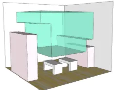
Quite commonly, indoor spaces are shaped like boxes, having uniform length, width and height. Prior to QUAV flights, we outlined free spaces for its movement using optimal distances, (i.e. buffered zones from obstacles for safety), which took into account length, width and height of indoor spaces we modelled. Since obstacles, such as walls, furniture, pillars and objects hang-ing from the ceilhang-ings can easily cause a QUAV to crash, so we only flied the UAV in free space (the green portion of Figure 1).
Safety Issues
Indoor spaces are enclosed by walls, columns and furniture. As such, there are many obstacles leading to safety issues for QUAV. Some spaces are too low, while others are too high, too small or too dangerous to fly a drone. Seeing as this is the case, we planned collision-free flight paths based on four factors: the size
of the QUAV, the field of view (FOV) of the camera,θ(as seen in Figure 2b, the goal of data collection and the dimensions of indoor environments. As shown in Figure 2, the QUAV should have a predefined safety distance,D, to walls and other obsta-cles (as well as people). We tried to ensure flight paths where walls and floors could be viewed simultaneously by the camera embedded in the QUAV, taking into accountDandθ. For some experiments, FOV was modified between flight paths to observe changes in level of detail given to objects in our 3D models. Fur-thermore, we did not attempt to fly the Parrot Bebop 2 within safety distances of furniture (such as tables, see Figure 3), be-cause it would likely have led to crashes.
Wall D
D
Wall
(a)
θ
Wall
Floor Camera
D θ
(b)
Figure 2. (a) safety distances for data acquisition as seen from above the QUAV, (b) the FOV of the camera carried by the
QUAV from a side-looking vantage point.
Figure 3. Table.
2.2 Accessibility
Space can be characterized by one of three categories based on accessibility: Private, Communal, orOpen Access (Paasch et al., 2015). Privatespaces are only legally accessible to a pri-vate party. Such a party can be one individual, a married cou-ple, group of peocou-ple, corporate body or non-profit organization.
Communalspace is subject to a right of common existing within
a community where each member has the right to use its holdings independently.Open Accessspaces have rights assigned to every-one; no one can be excluded. As is known to all, the majority of outdoor spaces areCommunalorOpen Access, but indoor space is generallyPrivate. In other words, indoor space has accessi-bility restrictions. Typical accessiaccessi-bility restrictions are present in places like offices which are only open to certain staff members during certain hours in certain rooms. Likewise, almost all rooms are forbidden for non-staff members in places like hospitals. Fur-thermore, people cannot enter private homes without the consent of the tenant. As such, UAV face the issue of accessibility in in-door space like people do, but often to a far greater extent.
Accessibility Issues
be dangerous. Many will not consent to being photographed or recorded. In areas, such as this, UAV can never be flown. Another example of a place that is forbidden for UAV flight is hospitals. Buildings such as this ban UAV flight, because they rely upon a quiet and safe environment for medical treatment at all hours of day and night. Most private buildings, likewise forbid UAV flight, for reasons specified or implied, unless permission is sought and granted by owners of these buildings.
2.3 Objects
In indoor space, most objects are artificial, small and numerous. Objects fall into one of five categories according to CityGML (Gr¨oger et al., 2012): Doors, Windows, Walls, Building Instal-lations and Building Furniture. However, for our 3D reconstruc-tion purposes, we classify indoor objects into the following cate-gories: architectural components, regularly-shaped furniture and irregularly-shaped furniture. Architectural components are nec-essary parts of buildings such as walls, floors, ceilings, doors and windows. Regularly-shaped furniture is furniture which has at least one surface that is regularly-shaped and larger than 0.5 m2, such as box-like fixtures (e.g. cabinets, lockers, sofas and ta-bles). Irregularly-shaped furniture consists of furniture and other objects with small surfaces such as chairs, books, phones, power lines and clothes.
Issues with Objects
Issues with objects often arise from texturing. Objects can be highly reflective, transparent or not textured at all. Data collec-tion is quite difficult when capturing blank walls, glass products and furniture. To make indoor spaces brighter, many walls are purposefully left blank and white. There are often decorations and other small objects attached to walls, but many of them are at a low position near the ground. Therefore, during certain experi-ments, it was quite difficult to find suitable places for CIPs place-ment necessary for photo alignplace-ment to process data for blank walls devoid of distinctive features. Another issue is presented by glass objects like windows and other transparent furniture. Win-dows can produce serious reflections off of UAV cameras and can also bring about large deformations of point clouds and meshes on account of improper alignment caused by the capture of out-door objects. Another problem is furniture. While QUAV have with high manoeuvrability, they still cannot safely traverse most furniture, necessitating flight paths not breaching safety distances mentioned in section 2.2.
2.4 Semantics
Semantics are important for indoor 3D models, because they as-sign meaning to objects based on their attributes (Horna et al., 2007). Without semantics, objects within images would not be discernible from one another. Semantics also provide meaning-ful signs and symbols which allow people or vehicles to better choose how to move via semantic-based navigation. For instance, semantic-based navigation, can be understood through spoken di-rections. A theoretical flight path could be described in seman-tics as: “flying straight along the Urbanism corridor then turning right, where there is a large room called BG.West.030. Once in-side this room, fly left until you‘ve arrived at the office of the 3D Geoinformation Research Group.” In this example, the Urban-ism corridor, room, BG.West.030, office and 3D Geoinformation Research Group are semantics necessary to comprehend the tra-jectory of a theoretical flight path.
Semantic Issues
Objects in indoor spaces have their own semantics which can be
classified for a variety of applications. For example, people want-ing to find a printer or coffee machine can use models constructed from data captured using a QUAV. We have to know and classify which object in this model is a printer and which is a coffee ma-chine. It‘s very easy for people to interpret this information from photos, but a tough job for computers to do, since there are many different objects in indoor space. Even the computer cannot dis-tinguish objects by their shapes, seeing as many objects in indoor space have similar shapes. Moreover, in logistical terms concern-ing reconstructconcern-ing 3D models, the sofa is part of the wall without semanitcs, since it is positioned against the wall itself. Seman-tics cannot be obtained and reconstructed from videos/photos di-rectly; a major flaw for our methodology employing close-range photogrammetry based on QUAV flights for indoor 3D model re-construction.
2.5 Other Issues
Issues with Light
For the purposes of our experiments, data acquisition is the pro-cess of recording videos or capturing photos via the camera em-bedded in the QUAV. The level of light has a big influence on the quality of photos and videos, seeing as poor lighting may cause underexposed photos, further affecting the quality of final 3D models. However, natural light in indoor space is not always enough. Therefore, we supplemented natural light with artificial light in order to guarantee that the camera received enough light to obtain clear data.
Issues with Noise
Noise in indoor 3D models is also an issue, although we can try to improve models by establishing goals for how they should look. Sometimes, however, we cannot remove all of the noise and are left with uneeded points in our model. For instance, when we needed an indoor 3D model without furniture, attention was paid to walls, floors and ceilings. For the sake of indoor 3D model re-construction, people who cross flight paths during video capture are unnecessary and unwanted because they cause noise distort-ing the objects behind them.
Issues with Occlusion
Occlusion was another impactful issue in our experiments. Image frames with objects such as light fixtures hanging from ceilings and pillars blocking objects behind them are highly detrimental to CIPs based alignment in Photoscan. The algorithm Photoscan has in place for marker detection is not sufficient for placement of CIPs where they cannot be seen in select frames as a result of occlusion. Nonetheless alignment in Photoscan demands CIPs in every frame be marked, even if their location is occluded by objects much closer to the QUAV camera. This leads to poor re-sults in resulting meshes and point clouds where occlusion makes alignment difficult to attain.
3. METHODOLOGY
3.1 Overview
and building textures which resulted in textured indoor 3D
mod-Building texture Textured mesh model
Building mesh Building dense point cloud
Matlab
Figure 4. Our workflow for flying QUAV for 3D indoor reconstruction.
3.2 Flight Path Design
The quality of the videos/images obtained directly determines the quality of the final three-dimensional model. In order to guaran-tee the quality of photos, we strove to fly the QUAV in suitable ways as dictated by indoor spatial dimensions. We payed close attention to the most important condition for photos, the over-lap requirement; 60% of side overover-lap and 80% of forward-facing overlap per consecutive frame. We designed flight paths based on two principles: 1, safety and security flying QUAV in indoor spaces and 2, data collection needed for the reconstruction of in-door 3D models. There are three suggestions for optimal image and video capture for the QUAV camera (Manual, 2014). For data acquisition of a faade, the QUAV should keep its on-board camera facing the faade while the QUAV itself moves horizon-tally, parallel to the faade, at an even height halfway between floor and ceiling, rather than remaining at one location and rotat-ing the on-board camera. For data collection of an entire indoor space, the QUAV should circle the space in an ovular pattern. During this time the QUAV camera should always be pointed in-wards toward the direct opposite ends of the room, rather than picking spots near corners and rotating 360◦without changing the way the camera faces. For isolated objects. In this scenario, the sensor should record video or take pictures around the object at many different locations, not only front, back, left and right, but also many angular positions.
Floor
Figure 5. Camera positioning, free space and the FOV of the camera.
We classified indoor spaces into three categories: rooms, corri-dors and stairs. Based on these categories we designed different flight path strategies incorporating four factors: the size of the
UAV, the FOV of the camera, the goal of data collection and the physical dimensions of data collection environments. To guar-antee high quality 3D models while expending the least possible motion, we designed flight paths for the QUAV based on the data acquisition suggestions. Height and width dimensions of indoor space,HandW, the FOV of the camera,l, as well as the require-ments for side overlap (60%), together determine the size of free space (shadowed areas in Figure 5).
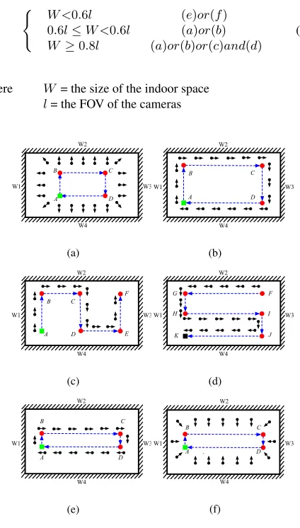
We designed flight paths based on the relationships betweenW andl, as seen in Equation 1, width and field of view juxtaposed with corresponding flight paths.
( W <0.6l (e)or(f) 0.6l≤W <0.6l (a)or(b)
W ≥0.8l (a)or(b)or(c)and(d)
(1)
where W = the size of the indoor space l= the FOV of the cameras
Figure 6. Flight paths for the QUAV.
used flight paths depcited in Figure 6e or 6f. These six flight path strategies can also be combined to create new flight paths for differently-shaped spaces. For example QUAV capture of T-shaped rooms, could benift form merging flight path strategies featured in Figure 6aand 6f.
3.3 Data Processing
Test were performed with the purpose of analyzing the possibil-ity to acquire and use QUAV video capture for indoor 3D model reconstruction. This allowed for evaluation of the effectiveness of our methods and provided a platform to identify procedural weaknesses. Alignment of images acquired by the QUAV cam-era was made possible by using the Structure from Motion (SfM) approach implemented in Photoscan. Input data required for this tool was only images since it was not necessary to know a pri-ori interior and exterior parameters of these cameras. In the first phase, the image elaboration lead to tie point extraction and photo alignment. This alignment algorithm found matching pixels by creating a sparse 3D point cloud. Once the images are aligned, it is then possible to import the Ground Control Points (GCPs), if available, to perform a bundle block adjustment (Boccardo et al., 2015) and compute the absolute orientation as well as geo-referenced the sparse point cloud (Manual, 2014). The next step toward indoor 3D model reconstruction was the generation of dense 3D point clouds. Subsequently, a triangulated mesh was produced and textured using images acquired from QUAV video capture.
3.4 Parameter Estimations
Direction of the Camera
2 4 5 7
3 m
5 m
7m
3 2 5 7
3 m
5 m
7 m
3
6 4 6
1 1
2 m 2 m
(a)
(b)
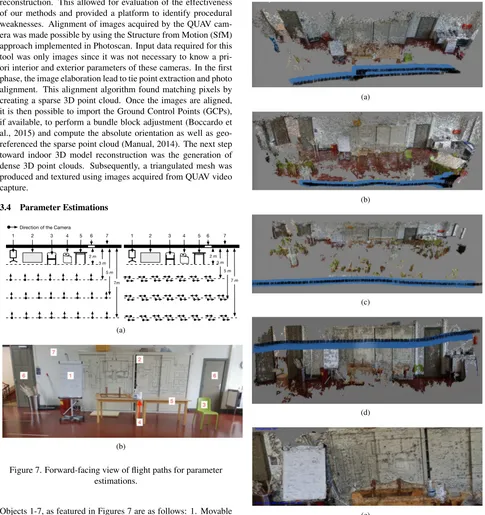
Figure 7. Forward-facing view of flight paths for parameter estimations.
Objects 1-7, as featured in Figures 7 are as follows: 1. Movable Whiteboard, 2. Locker, 3. Chair, 4. Roll of Paper Towels, 5. Table, 6. Doors and 7. Wall. Figures 7aleft and 7aright depict the direction of QUAV flights and camera positions for these par-ticular experiments. Figure 7bis an image of objects as they ap-peared in the TU Delft Science Centre Workshop 5 environment. In order to conduct parameter estimations for object reconstruc-tion pertaining to flight paths in Secreconstruc-tion 3.3, we carried out two
specific experiments seen in Figure 7a. It was our intention to merge key characteristics of previous flight paths in these exper-iments. In parameter estimation experiments we took all objects in indoor space into consideration including architectural compo-nents (e.g. walls, windows and doors), regularly-shaped furniture (e.g. movable whiteboards, lockers and tables) and irregularly-shaped furniture (e.g. rolls of paper, trash cans and chairs).
4. EXPERIMENTS
(a)
(b)
(c)
(d)
(e)
Figure 8. Dense Point clouds with aligned photos from parameter estimation experiments.
gen-erated point clouds of the first three paths, see Figure 8, in which the on-board camera is based on Figure 7a. For Figure 8a, the distance between the on-board camera and wall was three meters, while the distance between the camera and objects on the table was one meter. For Figure 8b, the distance was five meters to the wall and three meters to the objects on the table. For Figure 8c, the distance was seven meters from camera to wall and five me-ters from camera to table. Like Figure 8a, Figures 8dand 8ewere produced from the flight path one meter from the table and three meters from the wall. However, unlike Figures 8a, 8b, and 8c, the dense point cloud pictured in Figure 8dwas produced with ultra-high quality rather than ultra-high quality in Photoscan, and the direc-tion of the on-board camera is based on 7b. Seeing as Figure 8d depicts successfully rendered irregularly-shaped objects on the table, while Figure 8ahas no such clarity, we infer that ultra-high processing quality and the patience that requires is necessary to depict irregularly-shaped objects, even from as close as one meter away. Figure 8econfirms that meshes produced from ultra-high quality dense clouds do indeed depict irregularly-shaped objects with high levels of clarity. Nonetheless, gaps in the ultra-high quality dense point cloud still suggest that occlusion is an issue cannot be circumnavigated by processing power.
The results show that around 1 meter from the camera, furniture is suitable for 3D model reconstruction. However, the greater the distance between the camera and objects, the less realistic meshes became. Within five meters, wall reconstruction was fair, but around seven meters, the distance became too far to recon-struct any objects, even large, flat surfaces like a wall. In Figure 9a and 9b, the door, locker, movable whiteboard, table and wash-basin areas are comprised of pockets of dense points. However, due to subpar renderings of irregularly-shaped furniture, increas-ing distance from camera to object and large swaths of indoor space missing as a result of occlusion from pillars, challenges in indoor 3D reconstruction will likely persist in similar spaces where data capture is conducted with faulty flight paths.
4.1 Case Studies
Sofa Tables
Pillars
Lockers
Workshop 5
3D Geoinformation Round Table
Figure 9. Floor layouts of experiment environments.
Initially, we planned to reconstruct 3D mesh models with archi-tectural components, (e.g. walls, doors, windows, corridors and stairs) and regularly-shaped furniture, (e.g. tables, lockers and so-fas). These flight paths were created and flown in places such as a corridor outside Workshop 5 which connects with a stairwell (as seen in Figures 9 ). A series of experiments were also conducted in the office of the 3D Geoinformation Research Group (length: 11 meters, width: 7.1 meters, height: 5 meters) at Delft Univer-sity of Technology and Workshop 5 (length: 8.5 meters, width:
6 meters, height: 3.5 meters) in the TU Delft Science Centre. With the exception of two central pillars and three low-hanging light fixtures that run the width of Workshop 5, both Workshop 5 and the office of the 3D Geoinformation Research Group are indoor spaces with typical layouts: doors, windows, furniture, floors and walls (as seen in Figure 9). In the office of 3D Geoin-formation Research Group, there are three lockers, three sets of tables, two doors, three windows, one round-table and one sofa. While eight sets of tables, two pillars, one locker, two doors and seven windows are present in Workshop 5. It is noteworthy that there are many irregularly-shaped objects which cannot be fil-tered out directly, such as monitors, keyboards, phones, cups and books. Based on the above parameter estimation experiment, we set the FOV of the camera of the Bebop 2 at 90◦. The best data acquisition distance from the on-board camera to objects in this experiment was found to be roughly 1-2 meters. Our QUAV was flown manually along various flight paths, such as those depicted in Figures 7c and 7d, in both the office of the 3D Geoinformation Research Group and Workshop 5 of the TU Delft Science Centre. Flightpaths depicted in Figures 7e for the corridor and 7f for the stairs were chosen, because the width of the corridor and stairs were about 2 meters and 1.5 meters respectively.
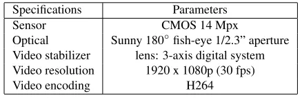
Specifications Parameters
Sensor CMOS 14 Mpx
Optical Sunny 180◦fish-eye 1/2.3” aperture Video stabilizer lens: 3-axis digital system Video resolution 1920 x 1080p (30 fps)
Video encoding H264
Table 1. Specifications of the Parrot Bebop 2
The Parrot Bebop 2 (as seen in Table 1) is an ideal indoor aerial vehicle, since it is lightweight (about 500g) and can offer 25 min-utes of continuous flight. Its high-performance specifications en-able it to fly, film and take photographs indoors.Photoscan can generate high-quality 3D models based on video it captures. The use of the latest multi-view image capturing techniques without the need to set initial parameters (i.e. intrinsic camera param-eters) is optimal when flying indoors. By eliminating the need for camera calibration, the use of the latest three-dimensional re-construction technology allows for alignment of overlapping im-ages needed for close-range photogrammetry. Image processing, can be conducting by using CIPs to improve the efficiency of alignment. Furthermore, our case studies suggest a wide range of factors should be considered when attempting indoor 3D re-construction such as occlusion of CIPs by furniture, blank walls, glare from outdoors and other subtle factors negatively influenc-ing alignment in Photoscan.
4.2 Results
is not properly performed. Therefore, they result in the gener-ation of noisy point clouds. Other sources of noise that cannot be ignored are irregularly-shaped objects (based on the classifi-cation rules in Section 2) in indoor space (e.g. monitors, key-boards, fans, cables). Another possible cause of noise is the in-stability of the sensor itself, because the Photoscan has difficulty in calculating the internal orientation of the camera and therefore there may be problems aligning images that cause inappropriate tie points and noise in the point cloud. We also found that there are many holes in correspondence with floor point clouds, which were probably caused by an inability to locate CIPs on account of noise from uniform colours frequently caused by subjection to glare/reflectance. The presence of moving people during video recording was also found to cause noise in some cases.
(a) (b)
(c) (d)
(e)
Figure 10. (a) and (b) are point cloud and mesh of the office of the 3D Geoinformation Research Group separately. (c) and (d)
are point cloud and mesh of the TU Delft Science Centre Workshop 5. (e) is the mesh of stairwell.
4.3 Discussion
Flying QUAV for 3D indoor model reconstruction has many chal-lenges; among them: safety issues, accessibility issues, object issues, semantic issues, light issues and noise issues. Semantic issues are related to reconstruction. Possibly we can address this issue by classifying objects based on a coloured point cloud, then assigning semantic information to them. Table 2 presents possi-ble solutions to the challenges faced in aerial indoor video capture for 3D reconstruction purposes.
Furthermore, 3D models reconstructed by this approach have in-herent advantages over free space (Diakit´e and Zlatanova, 2016)
extraction, since they have free space only (see Figure 11), a shell model, see Figure 11band 11d, e.g. lockers, tables, etc. are concave space in the model. However, because of this inherent feature, models constructed by this method also have a big disad-vantage that left out part of the space like the bottom of the table, where can be used as a escape space in emergency situations.
Challenges Potential solutions
Safety Issues Design flight paths based on safety dis-tances, the FOV of the camera (Section 3.3) and parameter estimation experi-ments (Section 4.1).
Accessibility Issues Ask people to leave, negotiate with peo-ple or fly the UAV during non-working hours.
Object Issues Remove, hide, or mask irregularly-shaped objects along your flight path whenever possible. Remove frames thought to be causing occlusion. Light Issues Turn on all lights in the modeled indoor
space, or conduct data acquisition on sunny days. Remove frames with glare prior to alignment
Noise Issues Put physical markers on blank walls, single-colored floors, etc. Cover glass portions of windows. Develop algo-rithms to mask the glass on windows automatically. Use UAV equipped with excellent sensors. Use steady, patient pilots to fly the UAV.
Table 2. Challenges in indoor UAV flight and potential solutions
Figure 11. The area with green rectangle in the mesh model is a locker, which is a concave space from the bottom view.
5. CONCLUSIONS
close-range flight paths coupled with powerful image processing software is highly advantageous.
We intend to carry out future work to improve the quality of in-door 3D models from five standpoints:
1. Tests regarding density of markers on blank walls, single-colored floors and furniture causing reflection, occlusion or noise. 2. Experiments to determine if there are techniques to aid align-ment in Photoscan through savvy placealign-ment of markers at differ-ent heights, depths or in differdiffer-ent patterns before recording the videos.
3. Research and/or development of algorithms to automate reli-able CIPs placement in Photoscan.
4. Cultivation and testing of flight paths for QUAV in places where more than one previously tested flight path can be merged to create new flight paths to examine optimal routing configura-tions and camera direcconfigura-tions in large indoor environments. 5. Take steps toward integration of autonomous QUAV flight ca-pabilities through coordination with colleagues at TU Delft and other academic affiliates.
ACKNOWLEDGEMENTS
The financial support for this work comes from the program of China Scholarships Council (No. 201606410054). This work has been supported by the Dutch project STW/M4S 13742 ‘Smart 3D indoor models to support crisis management in large public buildings‘ (www.sims3d.net).
REFERENCES
Alsadik, B., Gerke, M. and Vosselman, G., 2015. Efficient use of video for 3d modelling of cultural heritage objects.ISPRS Annals of the Photogrammetry, Remote Sensing and Spatial Information Sciences2(3), pp. 1.
Boccardo, P., Chiabrando, F., Dutto, F., Tonolo, F. G. and Lin-gua, A., 2015. Uav deployment exercise for mapping purposes: Evaluation of emergency response applications. Sensors15(7), pp. 15717–15737.
Diakit´e, A. A. and Zlatanova, S., 2016. Extraction of the 3d free space from building models for indoor navigation. ISPRS An-nals of Photogrammetry, Remote Sensing & Spatial Information Sciences.
Gr¨oger, G., Kolbe, T., Nagel, C. and H¨afele, K., 2012. Opengis city geography markup language (citygml) encoding standard v2.
0.0. Open Geospatial Consortium Standard. Open Geospatial
Consortium.
Hagedorn, B., Trapp, M., Glander, T. and D¨ollner, J., 2009. Towards an indoor level-of-detail model for route visualization.
In: Mobile Data Management: Systems, Services and
Middle-ware, 2009. MDM’09. Tenth International Conference on, IEEE,
pp. 692–697.
Horna, S., Damiand, G., Meneveaux, D. and Bertrand, Y., 2007. Building 3d indoor scenes topology from 2d architectural plans.
In:GRAPP (GM/R), pp. 37–44.
Hornung, A., Wurm, K. M., Bennewitz, M., Stachniss, C. and Burgard, W., 2013. Octomap: An efficient probabilistic 3d map-ping framework based on octrees. Autonomous Robots34(3), pp. 189–206.
Koska, B., 2011. Determination of st. george basilica tower his-torical inclination from contemporary photograph.
Geoinformat-ics FCE CTU6, pp. 212–219.
Lee, J. and Zlatanova, S., 2008. A 3d data model and topological analyses for emergency response in urban areas. Geospatial in-formation technology for emergency response. Taylor & Francis
Group, Londonpp. 143–165.
Lee, J., Li, K.-J., Zlatanova, S., Kolbe, T., Nagel, C. and Becker, T., 2014. Ogc indoorgml.Open Geospatial Consortium standard.
Li, K.-J., 2008. Indoor space: A new notion of space. In: In-ternational Symposium on Web and Wireless Geographical Infor-mation Systems, Springer, pp. 1–3.
Li, Y. and He, Z., 2008. 3d indoor navigation: a framework of combining bim with 3d gis. In:44th ISOCARP congress, pp. 1– 10.
LLC, G. M., 2009. Global mapper software llc.Parker, CO.
Manual, A. P. U., 2014. Professional edition. Aplastic Anemia (Hypoplastic Anemia).
Nex, F. and Remondino, F., 2014. Uav for 3d mapping applica-tions: a review.Applied Geomatics6(1), pp. 1–15.
Nikolov, I. and Madsen, C., 2016. Benchmarking close-range structure from motion 3d reconstruction software under vary-ing capturvary-ing conditions. In: Euro-Mediterranean Conference, Springer, pp. 15–26.
Paasch, J. M., van Oosterom, P., Lemmen, C. and Paulsson, J., 2015. Further modelling of ladm’s rights, restrictions and re-sponsibilities (rrrs).Land use policy49, pp. 680–689.
Remondino, F., Spera, M. G., Nocerino, E., Menna, F. and Nex, F., 2014. State of the art in high density image matching. The
Photogrammetric Record29(146), pp. 144–166.
Sebe, I. O., You, S. and Neumann, U., 2004. Dynamic objects modeling and 3d visualization.ASPRS04, Colorado, May.
Stoffel, E.-P., Lorenz, B. and Ohlbach, H. J., 2007. Towards a semantic spatial model for pedestrian indoor navigation. In:ER Workshops, Springer, pp. 328–337.
Strecha, C., 2011. Automated photogrammetric techniques on ultra-light uav imagery. Pix4D, http://www. pix4d.
com/downloads/pix4uav accuracy. pdfpp. 1–11.
Teuliere, C., Eck, L., Marchand, E. and Guenard, N., 2010. 3d model-based tracking for uav position control. In: Intelligent Robots and Systems (IROS), 2010 IEEE/RSJ International Con-ference on, IEEE, pp. 1084–1089.
Yan, J., Shang, J., Yu, F., Zhiyong, Z. and Tang, X., 2016. Indoor spatial structure and mapping methods for real-time localization.
Geomatics and Information Science of Wuhan University41(8),
pp. 1079–1086.
Yang, L. and Worboys, M., 2011a. A navigation ontology for outdoor-indoor space:(work-in-progress). In:Proceedings of the 3rd ACM SIGSPATIAL international workshop on indoor spatial
awareness, ACM, pp. 31–34.
Yang, L. and Worboys, M., 2011b. Similarities and differences between outdoor and indoor space from the perspective of navi-gation.Poster presented at COSIT.
Zlatanova, S., Sithole, G., Nakagawa, M. and Zhu, Q., 2013. Problems in indoor mapping and modelling. Acquisition and Modelling of Indoor and Enclosed Environments 2013, Cape Town, South Africa, 11-13 December 2013, ISPRS Archives
Vol-ume XL-4/W4, 2013.