Electrical and Electronic Principles
and Technology
Second edition
JOHN BIRD
,BSc(Hons) CEng CMath MIEE FIMA FIIE(ELEC) FCollP
OXFORD AMSTERDAM BOSTON LONDON NEW YORK PARIS
Newnes
An imprint of Elsevier Science
Linacre House, Jordan Hill, Oxford OX2 8DP 200 Wheeler Rd, Burlington MA 01803
Previously published asElectrical Principles and Technology for Engineering Reprinted 2001
Second edition 2003
Copyright2000, 2003, John Bird. All rights reserved
The right of John Bird to be identified as the author of this work has been asserted in accordance with the Copyright, Designs and Patents Act 1988
No part of this publication may be reproduced in any material form (including
photocopying or storing in any medium by electronic means and whether or not transiently or incidentally to some other use of this publication) without the written permission of the copyright holder except in accordance with the provisions of the Copyright, Designs and Patents Act 1988 or under the terms of a licence issued by the Copyright Licensing Agency Ltd, 90 Tottenham Court Road, London, England W1T 4LP. Applications for the copyright holder’s written permission to reproduce any part of this publication should be addressed to the publisher
British Library Cataloguing in Publication Data
A catalogue record for this book is available from the British Library
ISBN 0 7506 5778 2
For information on all Newnes publications visit our website at www.newnespress.com
Contents
Preface ix
SECTION 1 Basic Electrical and Electronic Engineering Principles 1
1 Units associated with basic electrical quantities 3
1.1 SI units 3 1.2 Charge 3 1.3 Force 4 1.4 Work 4 1.5 Power 4
1.6 Electrical potential and e.m.f. 5 1.7 Resistance and conductance 5 1.8 Electrical power and energy 6 1.9 Summary of terms, units and their
symbols 7
2 An introduction to electric circuits 9 2.1 Electrical/electronic system block
diagrams 9
2.2 Standard symbols for electrical components 10
2.3 Electric current and quantity of electricity 10
2.4 Potential difference and resistance 12
2.5 Basic electrical measuring instruments 12
2.6 Linear and non-linear devices 12 2.7 Ohm’s law 13
2.8 Multiples and sub-multiples 13 2.9 Conductors and insulators 14 2.10 Electrical power and energy 15 2.11 Main effects of electric
current 17 2.12 Fuses 18
3 Resistance variation 20
3.1 Resistance and resistivity 20 3.2 Temperature coefficient of
resistance 22
3.3 Resistor colour coding and ohmic values 25
4 Chemical effects of electricity 29 4.1 Introduction 29
4.2 Electrolysis 29 4.3 Electroplating 30 4.4 The simple cell 30 4.5 Corrosion 31
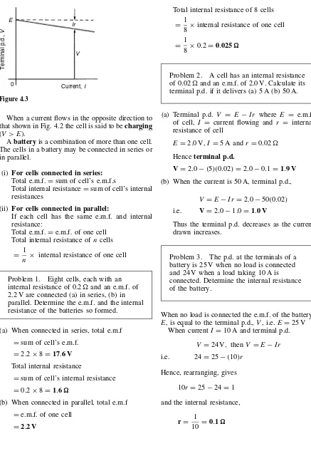
4.6 E.m.f. and internal resistance of a cell 31
4.7 Primary cells 34 4.8 Secondary cells 34 4.9 Cell capacity 35
Assignment 1 38
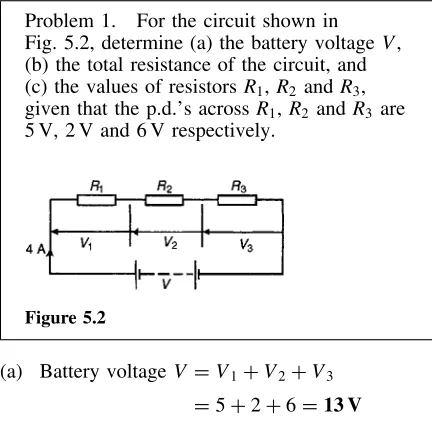
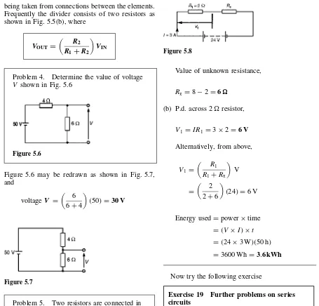
5 Series and parallel networks 39 5.1 Series circuits 39
5.2 Potential divider 40 5.3 Parallel networks 42 5.4 Current division 45
5.5 Wiring lamps in series and in parallel 49
6 Capacitors and capacitance 52 6.1 Electrostatic field 52 6.2 Electric field strength 53 6.3 Capacitance 54
6.4 Capacitors 54
6.5 Electric flux density 55 6.6 Permittivity 55
6.7 The parallel plate capacitor 57 6.8 Capacitors connected in parallel
and series 59
6.9 Dielectric strength 62
6.10 Energy stored in capacitors 63 6.11 Practical types of capacitor 64 6.12 Discharging capacitors 66
7 Magnetic circuits 68 7.1 Magnetic fields 68 7.2 Magnetic flux and flux
density 69
vi CONTENTS
7.6 Composite series magnetic circuits 74
7.7 Comparison between electrical and magnetic quantities 77 7.8 Hysteresis and hysteresis loss 77
Assignment 2 81
8 Electromagnetism 82
8.1 Magnetic field due to an electric current 82
8.2 Electromagnets 84 8.3 Force on a current-carrying
conductor 85
8.4 Principle of operation of a simple d.c. motor 89
8.5 Principle of operation of a moving-coil instrument 89 8.6 Force on a charge 90
9 Electromagnetic induction 93 9.1 Introduction to electromagnetic
induction 93
9.2 Laws of electromagnetic induction 94
9.3 Inductance 97 9.4 Inductors 98 9.5 Energy stored 99 9.6 Inductance of a coil 99 9.7 Mutual inductance 101
10 Electrical measuring instruments and measurements 104
10.1 Introduction 104
10.2 Analogue instruments 105 10.3 Moving-iron instrument 105 10.4 The moving-coil rectifier
instrument 105
10.5 Comparison of moving-coil, moving-iron and moving-coil rectifier instruments 106 10.6 Shunts and multipliers 106 10.7 Electronic instruments 108 10.8 The ohmmeter 108 10.9 Multimeters 109 10.10 Wattmeters 109
10.11 Instrument ‘loading’ effect 109 10.12 The cathode ray
oscilloscope 111
10.13 Waveform harmonics 114 10.14 Logarithmic ratios 115 10.15 Null method of
measurement 118 10.16 Wheatstone bridge 118
10.17 D.C. potentiometer 119 10.18 A.C. bridges 120 10.19 Q-meter 121
10.20 Measurement errors 122
11 Semiconductor diodes 127 11.1 Types of materials 127 11.2 Silicon and germanium 127 11.3 n-type and p-type materials 128 11.4 The p-n junction 129
11.5 Forward and reverse bias 129 11.6 Semiconductor diodes 130 11.7 Rectification 132
12 Transistors 136
12.1 The bipolar junction transistor 136 12.2 Transistor action 137 12.3 Transistor symbols 139 12.4 Transistor connections 139 12.5 Transistor characteristics 140 12.6 The transistor as an
amplifier 142 12.7 The load line 144
12.8 Current and voltage gains 145 12.9 Thermal runaway 147
Assignment 3 152
Formulae for basic electrical and electronic engineering principles 153
SECTION 2 Further Electrical and Electronic Principles 155
13 D.C. circuit theory 157 13.1 Introduction 157 13.2 Kirchhoff’s laws 157
13.3 The superposition theorem 161 13.4 General d.c. circuit theory 164 13.5 Th´evenin’s theorem 166 13.6 Constant-current source 171 13.7 Norton’s theorem 172
13.8 Th´evenin and Norton equivalent networks 175
13.9 Maximum power transfer theorem 179
14 Alternating voltages and currents 183 14.1 Introduction 183
CONTENTS vii
14.5 The equation of a sinusoidal waveform 189
14.6 Combination of waveforms 191 14.7 Rectification 194
Assignment 4 197
15 Single-phase series a.c. circuits 198 15.1 Purely resistive a.c. circuit 198 15.2 Purely inductive a.c. circuit 198 15.3 Purely capacitive a.c. circuit 199 15.4 R–Lseries a.c. circuit 201 15.5 R–Cseries a.c. circuit 204 15.6 R–L–Cseries a.c. circuit 206 15.7 Series resonance 209
15.8 Q-factor 210
15.9 Bandwidth and selectivity 212 15.10 Power in a.c. circuits 213 15.11 Power triangle and power
factor 214
16 Single-phase parallel a.c. circuits 219 16.1 Introduction 219
16.2 R–Lparallel a.c. circuit 219 16.3 R–Cparallel a.c. circuit 220 16.4 L–Cparallel a.c. circuit 222 16.5 LR–Cparallel a.c. circuit 223 16.6 Parallel resonance and
Q-factor 226
16.7 Power factor improvement 230
17 Filter networks 236 17.1 Introduction 236 17.2 Two-port networks and
characteristic impedance 236 17.3 Low-pass filters 237
17.4 High-pass filters 240 17.5 Band-pass filters 244 17.6 Band-stop filters 245
18 D.C. transients 248 18.1 Introduction 248
18.2 Charging a capacitor 248 18.3 Time constant for aC–R
circuit 249
18.4 Transient curves for aC–R circuit 250
18.5 Discharging a capacitor 253 18.6 Current growth in anL–R
circuit 255
18.7 Time constant for anL–R circuit 256
18.8 Transient curves for anL–R circuit 256
18.9 Current decay in anL–R circuit 257
18.10 Switching inductive circuits 260 18.11 The effects of time constant on a
rectangular waveform 260
19 Operational amplifiers 264 19.1 Introduction to operational
amplifiers 264
19.2 Some op amp parameters 266 19.3 Op amp inverting amplifier 267 19.4 Op amp non-inverting
amplifier 269
19.5 Op amp voltage-follower 270 19.6 Op amp summing amplifier 271 19.7 Op amp voltage comparator 272 19.8 Op amp integrator 272
19.9 Op amp differential amplifier 274
19.10 Digital to analogue (D/A) conversion 276
19.11 Analogue to digital (A/D) conversion 276
Assignment 5 281
Formulae for further electrical and electronic engineering principles 283
SECTION 3 Electrical Power Technology 285
20 Three-phase systems 287 20.1 Introduction 287 20.2 Three-phase supply 287 20.3 Star connection 288 20.4 Delta connection 291 20.5 Power in three-phase
systems 293
20.6 Measurement of power in three-phase systems 295 20.7 Comparison of star and delta
connections 300
20.8 Advantages of three-phase systems 300
21 Transformers 303 21.1 Introduction 303 21.2 Transformer principle of
operation 304
21.3 Transformer no-load phasor diagram 306
viii CONTENTS
21.5 Transformer on-load phasor diagram 310
21.6 Transformer construction 311 21.7 Equivalent circuit of
a transformer 312
21.8 Regulation of a transformer 313 21.9 Transformer losses and
efficiency 314
21.10 Resistance matching 317 21.11 Auto transformers 319 21.12 Isolating transformers 321 21.13 Three-phase transformers 321 21.14 Current transformers 323 21.15 Voltage transformers 324
Assignment 6 327
22 D.C. machines 328 22.1 Introduction 328
22.2 The action of a commutator 329 22.3 D.C. machine construction 329 22.4 Shunt, series and compound
windings 330
22.5 E.m.f. generated in an armature winding 330
22.6 D.C. generators 332
22.7 Types of d.c. generator and their characteristics 333
22.8 D.C. machine losses 337 22.9 Efficiency of a d.c.
generator 337 22.10 D.C. motors 338
22.11 Torque of a d.c. motor 339 22.12 Types of d.c. motor and their
characteristics 341 22.13 The efficiency of a d.c.
motor 344
22.14 D.C. motor starter 347
22.15 Speed control of d.c. motors 347 22.16 Motor cooling 350
23 Three-phase induction motors 354 23.1 Introduction 354
23.2 Production of a rotating magnetic field 354
22.3 Synchronous speed 356 23.4 Construction of a three-phase
induction motor 357 23.5 Principle of operation of a
three-phase induction motor 358 23.6 Slip 358
23.7 Rotor e.m.f. and frequency 359 23.8 Rotor impedance and
current 360
23.9 Rotor copper loss 361 22.10 Induction motor losses and
efficiency 361
23.11 Torque equation for an induction motor 363
23.12 Induction motor torque-speed characteristics 366
23.13 Starting methods for induction motors 367
23.14 Advantages of squirrel-cage induction motors 367 23.15 Advantages of wound rotor
induction motors 368 23.16 Double cage induction
motor 369
23.17 Uses of three-phase induction motors 369
Assignment 7 372
Formulae for electrical power technology 373
Answers to multi-choice questions 375
Preface
Electrical and Electronic Principles and Technol-ogy, 2nd edition introduces the principles which describe the operation of d.c. and a.c. circuits, cov-ering both steady and transient states, and applies these principles to filter networks (which is new for this edition), operational amplifiers, three-phase sup-plies, transformers, d.c. machines and three-phase induction motors.
This second edition of the textbook provides coverage of the following:
(i) ‘Electrical and Electronic Principles (National Certificate and National Diploma unit 6) (ii) ‘Further Electrical and Electronic Principles’
(National Certificate and National Diploma unit 17)
(iii) ‘Electrical and Electronic Principles’ (Advan-ced GNVQ unit 7)
(iv) ‘Further Electrical and Electronic Principles’ (Advanced GNVQ unit 13)
(v) ‘Electrical Power Technology’ (Advanced GNVQ unit 27)
(vi) Electricity content of ‘Applied Science and Mathematics for Engineering’ (Intermediate GNVQ unit 4)
(vii) The theory within ‘Electrical Principles and Applications’ (Intermediate GNVQ unit 6) (viii) ‘Telecommunication Principles’ (City &
Guilds Technician Diploma in Telecommuni-cations and Electronics Engineering)
(ix) Any introductory/Access/Foundation course involving Electrical and Electronic Engineer-ing
Thetextis set out in three main sections: Part 1, comprising chapters 1 to 12, involves essential Basic Electrical and Electronic Engi-neering Principles, with chapters on electrical units and quantities, introduction to electric circuits, resis-tance variation, chemical effects of electricity, series and parallel networks, capacitors and capacitance, magnetic circuits, electromagnetism, electromag-netic induction, electrical measuring instruments
and measurements, semiconductors diodes and transistors.
Part 2, comprising chapters 13 to 19, involves Further Electrical and Electronic Principles,with chapters on d.c. circuit theorems, alternating volt-ages and currents, single-phase series and parallel networks, filter networks, d.c. transients and opera-tional amplifiers.
Part 3, comprising chapters 20 to 23, involves Electrical Power Technology, with chapters on three-phase systems, transformers, d.c. machines and three-phase induction motors.
Each topic considered in the text is presented in a way that assumes in the reader little previ-ous knowledge of that topic. Theory is introduced in each chapter by a reasonably brief outline of essential information, definitions, formulae, proce-dures, etc. The theory is kept to a minimum, for problem solving is extensively used to establish and exemplify the theory. It is intended that readers will gain real understanding through seeing problems solved and then through solving similar problems themselves.
‘Electrical and Electronic Principles and Technol-ogy’ contains over400 worked problems, together with 340 multi-choice questions (with answers at the back of the book). Also included are over 420 short answer questions, the answers for which can be determined from the preceding material in that particular chapter, and some560 further questions, arranged in 142 Exercises, all with answers, in brackets, immediately following each question; the Exercises appear at regular intervals - every 3 or 4 pages - throughout the text.500 line diagrams fur-ther enhance the understanding of the theory. All of the problems - multi-choice, short answer and fur-ther questions - mirror practical situations found in electrical and electronic engineering.
x PREFACE
attempt as part of their course structure. Lecturers’ may obtain a complimentary set of solutions of the Assignments in an Instructor’s Manual available from the publishers via the internet – see below.
A list of relevant formulae are included at the end of each of the three sections of the book.
‘Learning by Example’is at the heart of Elec-trical and Electronic Principles and Technology, 2nd edition.
John Bird University of Portsmouth
Instructor’s Manual
Full worked solutions and mark scheme for all the Assignments are contained in this Manual, which is available to lecturers only. To obtain a password please e-mail [email protected] with the following details: course title, number of students, your job title and work postal address.
Section 1
1
Units associated with basic electrical
quantities
At the end of this chapter you should be able to:
ž state the basic SI units ž recognize derived SI units
ž understand prefixes denoting multiplication and division
ž state the units of charge, force, work and power and perform simple calculations involving these units
ž state the units of electrical potential, e.m.f., resistance, conductance, power and energy and perform simple calculations involving these units
1.1
SI units
The system of units used in engineering and science is the Syst`eme Internationale d’Unit´es (International system of units), usually abbreviated to SI units, and is based on the metric system. This was introduced in 1960 and is now adopted by the majority of countries as the official system of measurement.
The basic units in the SI system are listed below with their symbols:
Quantity Unit
length metre, m
mass kilogram, kg
time second, s
electric current ampere, A
thermodynamic temperature kelvin, K
luminous intensity candela, cd
amount of substance mole, mol
Derived SI units use combinations of basic units and there are many of them. Two examples are:
Velocity – metres per second (m/s)
Acceleration – metres per second squared (m/s2)
SI units may be made larger or smaller by using prefixes which denote multiplication or division by a particular amount. The six most common multiples, with their meaning, are listed below:
Prefix Name Meaning
M mega multiply by 1 000 000 (i.e.ð106) k kilo multiply by 1000 (i.e.ð103) m milli divide by 1000 (i.e.ð103)
µ micro divide by 1 000 000 (i.e.ð106) n nano divide by 1 000 000 000
(i.e.ð109)
p pico divide by 1 000 000 000 000 (i.e.ð1012)
1.2
Charge
4 ELECTRICAL AND ELECTRONIC PRINCIPLES AND TECHNOLOGY
6.24ð1018 electrons). The coulomb is defined as the quantity of electricity which flows past a given point in an electric circuit when a current of one ampere is maintained for one second. Thus,
charge, in coulombs Q =It
where I is the current in amperes andt is the time in seconds.
Problem 1. If a current of 5 A flows for 2 minutes, find the quantity of electricity transferred.
Quantity of electricityQDItcoulombs ID5 A, tD2ð60D120 s Hence QD5ð120D600 C
1.3
Force
The unit of force is the newton (N) where one newton is one kilogram metre per second squared. The newton is defined as the force which, when applied to a mass of one kilogram, gives it an acceleration of one metre per second squared. Thus,
force, in newtons F =ma
wheremis the mass in kilograms andais the accel-eration in metres per second squared. Gravitational force, or weight, ismg, where gD9.81 m/s2
Problem 2. A mass of 5000 g is accelerated at 2 m/s2 by a force. Determine the force needed.
ForceDmassðacceleration
D5 kgð2 m/s2D10 kg m/s2D10 N Problem 3. Find the force acting vertically downwards on a mass of 200 g attached to a wire.
Mass D 200 g D 0.2 kg and acceleration due to gravity,gD9.81 m/s2
Force acting downwards
Dweight
Dmassðacceleration D0.2 kgð9.81 m/s2 D1.962 N
1.4
Work
Theunit of work or energyis thejoule (J)where one joule is one newton metre. The joule is defined as the work done or energy transferred when a force of one newton is exerted through a distance of one metre in the direction of the force. Thus
work done on a body, in joules, W =Fs
whereFis the force in newtons andsis the distance in metres moved by the body in the direction of the force. Energy is the capacity for doing work.
1.5
Power
Theunit of poweris the watt (W) where one watt is one joule per second. Power is defined as the rate of doing work or transferring energy. Thus,
power, in watts, P = W
t
whereWis the work done or energy transferred, in joules, andtis the time, in seconds. Thus,
energy, in joules, W =Pt
Problem 4. A portable machine requires a force of 200 N to move it. How much work is done if the machine is moved 20 m and what average power is utilized if the movement takes 25 s?
UNITS ASSOCIATED WITH BASIC ELECTRICAL QUANTITIES 5
PowerD work done time taken
D 4000 J
25 s D160 J=s=160 W Problem 5. A mass of 1000 kg is raised through a height of 10 m in 20 s. What is (a) the work done and (b) the power developed?
(a) Work doneDforceðdistance and force Dmassðacceleration
Hence,
work done D⊲1000 kgð9.81 m/s 2
⊳ð⊲10 m⊳ D98 100 Nm
D98.1 kNmor98.1 kJ (b) PowerD work done
time taken D
98100 J 20 s
D4905 J/sD4905 Wor4.905 kW
Now try the following exercise
Exercise 1 Further problems on charge, force, work and power
(TakegD9.81 m/s2 where appropriate)
1 What quantity of electricity is carried by 6.24ð1021electrons? [1000 C] 2 In what time would a current of 1 A transfer
a charge of 30 C? [30 s]
3 A current of 3 A flows for 5 minutes. What charge is transferred? [900 C]
4 How long must a current of 0.1 A flow so as to transfer a charge of 30 C? [5 minutes]
5 What force is required to give a mass of 20 kg an acceleration of 30 m/s2? [600 N]
6 Find the accelerating force when a car having a mass of 1.7 Mg increases its speed with a constant acceleration of 3 m/s2 [5.1 kN]
7 A force of 40 N accelerates a mass at 5 m/s2.
Determine the mass. [8 kg]
8 Determine the force acting downwards on a mass of 1500 g suspended on a string. [14.72 N]
9 A force of 4 N moves an object 200 cm in the direction of the force. What amount of work
is done? [8 J]
10 A force of 2.5 kN is required to lift a load. How much work is done if the load is lifted
through 500 cm? [12.5 kJ]
11 An electromagnet exerts a force of 12 N and moves a soft iron armature through a distance of 1.5 cm in 40 ms. Find the power consumed. [4.5 W]
12 A mass of 500 kg is raised to a height of 6 m in 30 s. Find (a) the work done and (b) the power developed.
[(a) 29.43 kNm (b) 981 W]
1.6
Electrical potential and e.m.f.
Theunit of electric potentialis the volt (V), where one volt is one joule per coulomb. One volt is defined as the difference in potential between two points in a conductor which, when carrying a cur-rent of one ampere, dissipates a power of one watt, i.e.
voltsD watts amperes D
joules/second amperes
D joules
ampere seconds D
joules coulombs
A change in electric potential between two points in an electric circuit is called a potential difference. The electromotive force (e.m.f.) provided by a source of energy such as a battery or a generator is measured in volts.
1.7
Resistance and conductance
6 ELECTRICAL AND ELECTRONIC PRINCIPLES AND TECHNOLOGY
at the two points produces a current flow of one ampere in the conductor. Thus,
resistance, in ohms R= V
I
where V is the potential difference across the two points, in volts, andIis the current flowing between the two points, in amperes.
The reciprocal of resistance is calledconductance and is measured in siemens (S). Thus
conductance, in siemens G= 1
R
where Ris the resistance in ohms. Problem 6. Find the conductance of a conductor of resistance: (a) 10(b) 5 k (c) 100 m.
(a) ConductanceGD 1 R D
1
10 siemenD0.1 S (b) GD 1
R D 1
5ð103SD0.2ð10
3SD0.2 mS
(c) GD 1 R D
1
100ð103SD 103
100SD10 S
1.8
Electrical power and energy
When a direct current ofI amperes is flowing in an electric circuit and the voltage across the circuit is Vvolts, then
power, in watts P =VI
Electrical energyDPowerðtime DVIt joules
Although the unit of energy is the joule, when dealing with large amounts of energy, the unit used is thekilowatt hour (kWh)where
1 kWhD1000 watt hour
D1000ð3600 watt seconds or joules D3 600 000 J
Problem 7. A source e.m.f. of 5 V supplies a current of 3 A for 10 minutes. How much energy is provided in this time?
Energy D powerðtime, and power D voltageð current. Hence
EnergyDVItD5ð3ð⊲10ð60⊳ D9000 Ws or JD9 kJ Problem 8. An electric heater consumes 1.8 MJ when connected to a 250 V supply for 30 minutes. Find the power rating of the heater and the current taken from the supply.
PowerD energy time D
1.8ð106J 30ð60 s
D1000 J/sD1000 W i.e.power rating of heaterD1 kW
PowerPDVI, thusID P V D
1000 250 D4 A Hence the current taken from the supply is 4 A.
Now try the following exercise
Exercise 2 Further problems on e.m.f., resistance, conductance, power and energy 1 Find the conductance of a resistor of resistance
(a) 10(b) 2 k(c) 2 m
[(a) 0.1 S (b) 0.5 mS (c) 500 S]
2 A conductor has a conductance of 50µS. What
is its resistance? [20 k]
3 An e.m.f. of 250 V is connected across a tance and the current flowing through the resis-tance is 4 A. What is the power developed? [1 kW]
4 450 J of energy are converted into heat in 1 minute. What power is dissipated? [7.5 W]
UNITS ASSOCIATED WITH BASIC ELECTRICAL QUANTITIES 7
6 A battery of e.m.f. 12 V supplies a current of 5 A for 2 minutes. How much energy is supplied in this time? [7.2 kJ]
7 A d.c. electric motor consumes 36 MJ when connected to a 250 V supply for 1 hour. Find the power rating of the motor and the current taken from the supply. [10 kW, 40 A]
1.9
Summary of terms, units and
their symbols
Quantity Quantity Unit Unit
Symbol Symbol
Length l metre m
Mass m kilogram kg
Time t second s
Velocity v metres per m/s or
second m s1 Acceleration a metres per m/s2 or
second m s2 squared
Force F newton N
Electrical Q coulomb C
charge or quantity
Electric current I ampere A
Resistance R ohm
Conductance G siemen S
Electromotive E volt V
force
Potential V volt V
difference
Work W joule J
Energy E (or W) joule J
Power P watt W
Now try the following exercises
Exercise 3 Short answer questions on units associated with basic electrical quantities
1 What does ‘SI units’ mean?
2 Complete the following:
ForceD. . . .ð. . . .
3 What do you understand by the term ‘poten-tial difference’?
4 Define electric current in terms of charge and time
5 Name the units used to measure: (a) the quantity of electricity (b) resistance
(c) conductance 6 Define the coulomb
7 Define electrical energy and state its unit 8 Define electrical power and state its unit 9 What is electromotive force?
10 Write down a formula for calculating the power in a d.c. circuit
11 Write down the symbols for the following quantities:
(a) electric charge (b) work
(c) e.m.f. (d) p.d.
12 State which units the following abbreviations refer to:
(a) A (b) C (c) J (d) N (e) m
Exercise 4 Multi-choice questions on units associated with basic electrical quantities (Answers on page 375)
1 A resistance of 50 khas a conductance of:
(a) 20 S (b) 0.02 S
(c) 0.02 mS (d) 20 kS
2 Which of the following statements is incor-rect?
(a) 1 ND1 kg m/s2 (b) 1 VD1 J/C (c) 30 mAD0.03 A (d) 1 JD1 N/m 3 The power dissipated by a resistor of 10
when a current of 2 A passes through it is: (a) 0.4 W (b) 20 W (c) 40 W (d) 200 W
4 A mass of 1200 g is accelerated at 200 cm/s2 by a force. The value of the force required is:
(a) 2.4 N (b) 2400 N
(c) 240 kN (d) 0.24 N
5 A charge of 240 C is transferred in 2 minutes. The current flowing is:
(a) 120 A (b) 480 A (c) 2 A (d) 8 A
8 ELECTRICAL AND ELECTRONIC PRINCIPLES AND TECHNOLOGY
(a) 0.5 kWh (b) 4 kWh
(c) 2 kWh (d) 0.02 kWh
7 The unit of quantity of electricity is the:
(a) volt (b) coulomb
(c) ohm (d) joule
8 Electromotive force is provided by: (a) resistance’s
(b) a conducting path (c) an electric current
(d) an electrical supply source
9 The coulomb is a unit of: (a) power
(b) voltage
(c) energy
(d) quantity of electricity
10 In order that work may be done: (a) a supply of energy is required (b) the circuit must have a switch (c) coal must be burnt
(d) two wires are necessary
11 The ohm is the unit of:
(a) charge (b) resistance
(c) power (d) current
12 The unit of current is the:
(a) volt (b) coulomb
2
An introduction to electric circuits
At the end of this chapter you should be able to:
ž appreciate that engineering systems may be represented by block diagrams ž recognize common electrical circuit diagram symbols
ž understand that electric current is the rate of movement of charge and is measured in amperes
ž appreciate that the unit of charge is the coulomb
ž calculate charge or quantity of electricity QfromQDIt
ž understand that a potential difference between two points in a circuit is required for current to flow
ž appreciate that the unit of p.d. is the volt
ž understand that resistance opposes current flow and is measured in ohms
ž appreciate what an ammeter, a voltmeter, an ohmmeter, a multimeter and a C.R.O. measure
ž distinguish between linear and non-linear devices ž state Ohm’s law as VDIRorIDV/RorRDV/I
ž use Ohm’s law in calculations, including multiples and sub-multiples of units ž describe a conductor and an insulator, giving examples of each
ž appreciate that electrical powerPis given byPDVIDI2RDV2/Rwatts ž calculate electrical power
ž define electrical energy and state its unit ž calculate electrical energy
ž state the three main effects of an electric current, giving practical examples of each ž explain the importance of fuses in electrical circuits
2.1
Electrical/electronic system block
diagrams
An electrical/electronic system is a group of com-ponents connected together to perform a desired function. Figure 2.1 shows a simple public address
10 ELECTRICAL AND ELECTRONIC PRINCIPLES AND TECHNOLOGY
A sub-system is a part of a system which per-forms an identified function within the whole sys-tem; the amplifier in Fig. 2.1 is an example of a sub-system
Acomponentorelementis usually the simplest part of a system which has a specific and well-defined function – for example, the microphone in Fig. 2.1
The illustration in Fig. 2.1 is called a block dia-gram and electrical/electronic systems, which can often be quite complicated, can be better understood when broken down in this way. It is not always necessary to know precisely what is inside each sub-system in order to know how the whole system functions.
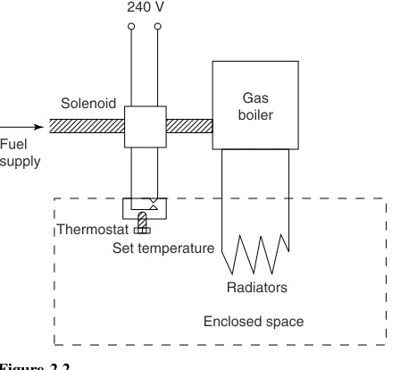
As another example of an engineering system, Fig. 2.2 illustrates a temperature control system con-taining a heat source (such as a gas boiler), a fuel controller (such as an electrical solenoid valve), a thermostat and a source of electrical energy. The system of Fig. 2.2 can be shown in block diagram form as in Fig. 2.3; the thermostat compares the
Solenoid
actual room temperature with the desired temper-ature and switches the heating on or off.
There are many types of engineering systems. A communications system is an example, where a local area network could comprise a file server, coaxial cable, network adapters, several computers and a laser printer; anelectromechanical systemis another example, where a car electrical system could comprise a battery, a starter motor, an ignition coil, a contact breaker and a distributor. All such systems as these may be represented by block diagrams.
2.2
Standard symbols for electrical
components
Symbols are used for components in electrical cir-cuit diagrams and some of the more common ones are shown in Fig. 2.4
2.3
Electric current and quantity of
electricity
All atoms consist of protons, neutrons and elec-trons. The protons, which have positive electrical charges, and the neutrons, which have no electrical charge, are contained within thenucleus. Removed from the nucleus are minute negatively charged par-ticles called electrons. Atoms of different materials differ from one another by having different numbers of protons, neutrons and electrons. An equal number of protons and electrons exist within an atom and it is said to be electrically balanced, as the positive and negative charges cancel each other out. When there are more than two electrons in an atom the electrons are arranged intoshellsat various distances from the nucleus.
AN INTRODUCTION TO ELECTRIC CIRCUITS 11
Figure 2.4
It is possible for an atom to lose an electron; the atom, which is now called an ion, is not now electrically balanced, but is positively charged and is thus able to attract an electron to itself from another atom. Electrons that move from one atom to another are called free electrons and such random motion can continue indefinitely. However, if an electric pressure or voltage is applied across any material there is a tendency for electrons to move in a particular direction. This movement of free electrons, known as drift, constitutes an electric current flow.Thus current is the rate of movement of charge.
Conductors are materials that contain electrons that are loosely connected to the nucleus and can easily move through the material from one atom to another.
Insulatorsare materials whose electrons are held firmly to their nucleus.
The unit used to measure the quantity of elec-trical charge Q is called the coulomb C(where 1 coulombD6.24ð1018electrons)
If the drift of electrons in a conductor takes place at the rate of one coulomb per second the resulting
current is said to be a current of one ampere.
Thus 1 ampereD1 coulomb per second or 1 AD1 C/s
Hence 1 coulombD1 ampere second or 1 CD1 As
Generally, if I is the current in amperes and t the time in seconds during which the current flows, then I ðt represents the quantity of electrical charge in coulombs, i.e. quantity of electrical charge trans-ferred,
Q=I ×t coulombs
Problem 1. What current must flow if 0.24 coulombs is to be transferred in 15 ms?
Since the quantity of electricity,QDIt, then
ID Q t D
0.24 15ð103 D
0.24ð103 15
D 240
15 D16 A
Problem 2. If a current of 10 A flows for four minutes, find the quantity of electricity transferred.
Quantity of electricity,Q DItcoulombs. I D10 A andtD4ð60D240 s. Hence
Q D10ð240D2400 C
Now try the following exercise
Exercise 5 Further problems on charge 1 In what time would a current of 10 A transfer
a charge of 50 C ? [5 s]
2 A current of 6 A flows for 10 minutes. What charge is transferred ? [3600 C]
12 ELECTRICAL AND ELECTRONIC PRINCIPLES AND TECHNOLOGY
2.4
Potential difference and resistance
For a continuous current to flow between two points in a circuit apotential difference (p.d.)orvoltage,
V, is required between them; a complete conducting path is necessary to and from the source of electrical energy. The unit of p.d. is the volt,V.
Figure 2.5 shows a cell connected across a fila-ment lamp. Current flow, by convention, is consid-ered as flowing from the positive terminal of the cell, around the circuit to the negative terminal.
Figure 2.5
The flow of electric current is subject to friction. This friction, or opposition, is called resistance R
and is the property of a conductor that limits current. The unit of resistance is the ohm; 1 ohm is defined as the resistance which will have a current of 1 ampere flowing through it when 1 volt is connected across it,
i.e. resistanceR= Potential difference current
2.5
Basic electrical measuring
instruments
An ammeter is an instrument used to measure current and must be connected in series with the circuit. Figure 2.5 shows an ammeter connected in series with the lamp to measure the current flowing through it. Since all the current in the circuit passes through the ammeter it must have a verylow resistance.
A voltmeter is an instrument used to measure p.d. and must be connectedin parallelwith the part of the circuit whose p.d. is required. In Fig. 2.5, a voltmeter is connected in parallel with the lamp to measure the p.d. across it. To avoid a significant
current flowing through it a voltmeter must have a veryhigh resistance.
An ohmmeter is an instrument for measuring resistance.
A multimeter, or universal instrument, may be used to measure voltage, current and resistance. An ‘Avometer’ is a typical example.
The cathode ray oscilloscope (CRO) may be used to observe waveforms and to measure voltages and currents. The display of a CRO involves a spot of light moving across a screen. The amount by which the spot is deflected from its initial position depends on the p.d. applied to the terminals of the CRO and the range selected. The displacement is calibrated in ‘volts per cm’. For example, if the spot is deflected 3 cm and the volts/cm switch is on 10 V/cm then the magnitude of the p.d. is 3 cmð10 V/cm, i.e. 30 V.
(See Chapter 10 for more detail about electrical measuring instruments and measurements.)
2.6
Linear and non-linear devices
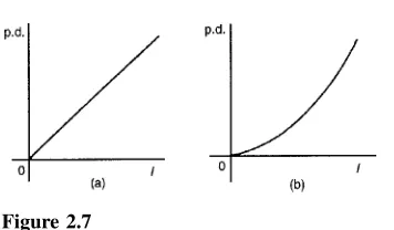
Figure 2.6 shows a circuit in which current I can be varied by the variable resistor R2. For various settings of R2, the current flowing in resistor R1, displayed on the ammeter, and the p.d. across R1, displayed on the voltmeter, are noted and a graph is plotted of p.d. against current. The result is shown in Fig. 2.7(a) where the straight line graph passing through the origin indicates that current is directly proportional to the p.d. Since the gradient, i.e. ⊲p.d.⊳/⊲current⊳ is constant, resistance R1 is constant. A resistor is thus an example of alinear device.
Figure 2.6
AN INTRODUCTION TO ELECTRIC CIRCUITS 13
Figure 2.7
changing, the lamp is an example of a non-linear device.
2.7
Ohm’s law
Ohm’s law states that the current I flowing in a circuit is directly proportional to the applied voltage V and inversely proportional to the resistance R, provided the temperature remains constant. Thus,
I = V
R or V =IR or R= V
I
Problem 3. The current flowing through a resistor is 0.8 A when a p.d. of 20 V is applied. Determine the value of the resistance.
From Ohm’s law,
resistance RD V I D
20 0.8D
200
8 D25Z
2.8
Multiples and sub-multiples
Currents, voltages and resistances can often be very large or very small. Thus multiples and sub-multiples of units are often used, as stated in chap-ter 1. The most common ones, with an example of each, are listed in Table 2.1
Problem 4. Determine the p.d. which must be applied to a 2 kresistor in order that a current of 10 mA may flow.
ResistanceRD2 kD2ð103 D2000
CurrentID10 mAD10ð103A or 10
103A or 10
1000AD0.01 A
From Ohm’s law, potential difference,
VDIRD⊲0.01⊳⊲2000⊳D20 V
Problem 5. A coil has a current of 50 mA flowing through it when the applied voltage is 12 V. What is the resistance of the coil?
Resistance,RD V I D
12 50ð103
D 12ð10 3
50 D
12 000
50 D240Z
Table 2.1
Prefix Name Meaning Example
M mega multiply by 1 000 000 2 MD2 000 000 ohms ⊲i.e.ð106⊳
k kilo multiply by 1000 10 kVD10 000 volts
⊲i.e.ð103⊳
m milli divide by 1000 25 mAD 25
1000A ⊲i.e.ð103⊳ D0.025 amperes
µ micro divide by 1 000 000 50µVD 50
14 ELECTRICAL AND ELECTRONIC PRINCIPLES AND TECHNOLOGY
Problem 6. A 100 V battery is connected across a resistor and causes a current of 5 mA to flow. Determine the resistance of the resistor. If the voltage is now reduced to 25 V, what will be the new value of the current flowing?
ResistanceRD V I D
100 5ð103 D
100ð103 5
D20ð103 D20 kZ Current when voltage is reduced to 25 V,
ID V R D
25 20ð103 D
25 20 ð10
3 D1.25 mA
Problem 7. What is the resistance of a coil which draws a current of (a) 50 mA and (b) 200µA from a 120 V supply?
(a) ResistanceRD V I D
120 50ð103 D 120
0.05 D 12 000
5 D2400Zor2.4 kZ (b) ResistanceRD 120
200ð106 D 120 0.0002
D 1 200 000
2 D600 000Z or600 kZor0.6 MZ Problem 8. The current/voltage relationship for two resistors A and B is as shown in Fig. 2.8 Determine the value of the resistance of each resistor.
For resistor A,
RD V I D
20 V 20 mA D
20 0.02 D
2000 2 D1000Zor1 kZ
For resistor B,
RD V I D
16 V 5 mA D
16 0.005 D
16 000 5 D3200Zor3.2 kZ
Figure 2.8
Now try the following exercise
Exercise 6 Further problems on Ohm’s law
1 The current flowing through a heating element is 5 A when a p.d. of 35 V is applied across it. Find the resistance of the element. [7] 2 A 60 W electric light bulb is connected to a 240 V supply. Determine (a) the current flow-ing in the bulb and (b) the resistance of the
bulb. [(a) 0.25 A (b) 960]
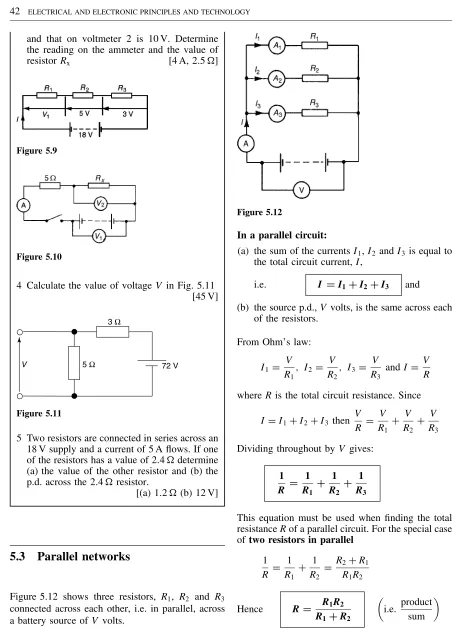
3 Graphs of current against voltage for two resis-tors P and Q are shown in Fig. 2.9 Determine the value of each resistor. [2 m, 5 m]
Figure 2.9
4 Determine the p.d. which must be applied to a 5 kresistor such that a current of 6 mA may
flow. [30 V]
2.9
Conductors and insulators
AN INTRODUCTION TO ELECTRIC CIRCUITS 15
are conductors and some examples include copper, aluminium, brass, platinum, silver, gold and carbon. An insulator is a material having a high resis-tance which does not allow electric current to flow in it. Some examples of insulators include plastic, rub-ber, glass, porcelain, air, paper, cork, mica, ceramics and certain oils.
2.10
Electrical power and energy
Electrical power
Power P in an electrical circuit is given by the product of potential difference V and current I, as stated in Chapter 1. The unit of power is the watt,W.
Hence P =V ×Iwatts ⊲1⊳
From Ohm’s law, V D IR. Substituting for V in equation (1) gives:
PD⊲IR⊳ðI
i.e. P =I2Rwatts
Also, from Ohm’s law,IDV/R. Substituting forI in equation (1) gives:
PDVðV R
i.e. P = V
2
R watts
There are thus three possible formulae which may be used for calculating power.
Problem 9. A 100 W electric light bulb is connected to a 250 V supply. Determine (a) the current flowing in the bulb, and (b) the resistance of the bulb.
PowerPDVðI, from which, currentID P V
(a) CurrentID 100 250 D
10 25 D
2
5D0.4 A (b) ResistanceRD V
I D 250
0.4 D 2500
4 D625Z
Problem 10. Calculate the power dissipated when a current of 4 mA flows through a resistance of 5 k.
PowerP DI2RD⊲4ð103⊳2⊲5ð103⊳ D16ð106ð5ð103 D80ð103
D0.08 W or80 mW
Alternatively, since ID4ð103 and RD5ð103 then from Ohm’s law, voltage
VDIRD4ð103ð5ð103D20 V Hence,
powerP DVðID20ð4ð103 D80 mW
Problem 11. An electric kettle has a resistance of 30. What current will flow when it is connected to a 240 V supply? Find also the power rating of the kettle.
Current,ID V R D
240 30 D8 A
Power, PDVID240ð8D1920 W
D1.92 kWDpower rating of kettle
Problem 12. A current of 5 A flows in the winding of an electric motor, the resistance of the winding being 100. Determine (a) the p.d. across the winding, and (b) the power dissipated by the coil.
(a) Potential difference across winding,
VDIRD5ð100D500 V (b) Power dissipated by coil,
PDI2RD52ð100 D2500 Wor2.5 kW (Alternatively, PDVðID500ð5
16 ELECTRICAL AND ELECTRONIC PRINCIPLES AND TECHNOLOGY
Problem 13. The hot resistance of a 240 V filament lamp is 960. Find the current taken by the lamp and its power rating.
From Ohm’s law,
current ID V R D
240 960
D 24 96 D
1
4Aor0.25 A Power ratingPDVID⊲240⊳14D60 W
Electrical energy
Electrical energy=power×time If the power is measured in watts and the time in seconds then the unit of energy is watt-seconds or joules. If the power is measured in kilowatts and the time in hours then the unit of energy is kilowatt-hours, often called the ‘unit of electricity’. The ‘electricity meter’ in the home records the number of kilowatt-hours used and is thus an energy meter.
Problem 14. A 12 V battery is connected across a load having a resistance of 40. Determine the current flowing in the load, the power consumed and the energy dissipated in 2 minutes.
CurrentID V R D
12
40 D0.3 A
Power consumed, PDVID⊲12⊳⊲0.3⊳D3.6 W. Energy dissipatedDpowerðtime
D⊲3.6 W⊳⊲2ð60 s⊳ D432 J(since1 JD1 Ws⊳ Problem 15. A source of e.m.f. of 15 V supplies a current of 2 A for 6 minutes. How much energy is provided in this time?
Energy D powerðtime, and power D voltageð current. Hence
energyDVItD15ð2ð⊲6ð60⊳ D10 800 Ws or JD10.8 kJ
Problem 16. Electrical equipment in an office takes a current of 13 A from a 240 V supply. Estimate the cost per week of electricity if the equipment is used for 30 hours each week and 1 kWh of energy costs 6p.
PowerDVIwattsD240ð13 D3120 WD3.12 kW
Energy used per weekDpowerðtime D⊲3.12 kW⊳ð⊲30 h⊳ D93.6 kWh
Cost at 6p per kWhD 93.6ð6D 561.6p. Hence weekly cost of electricity=£5.62
Problem 17. An electric heater consumes 3.6 MJ when connected to a 250 V supply for 40 minutes. Find the power rating of the heater and the current taken from the supply.
PowerD energy time D
3.6ð106 40ð60
J
s (or W)D1500 W i.e. Power rating of heaterD1.5 kW.
PowerPDVI,
thus ID P V D
1500 250 D6 A
Hence the current taken from the supply is6 A.
Problem 18. Determine the power dissipated by the element of an electric fire of resistance 20when a current of 10 A flows through it. If the fire is on for 6 hours determine the energy used and the cost if 1 unit of electricity costs 6.5p.
PowerPDI2RD102ð20
D100ð20D2000 Wor2 kW. (Alternatively, from Ohm’s law,
VDIRD10ð20D200 V, hence power
AN INTRODUCTION TO ELECTRIC CIRCUITS 17
Energy used in 6 hoursDpowerðtimeD2 kWð 6 hD12 kWh.
1 unit of electricity D1 kWh; hence the number of units used is 12. Cost of energyD12ð6.5D78p
Problem 19. A business uses two 3 kW fires for an average of 20 hours each per week, and six 150 W lights for 30 hours each per week. If the cost of electricity is 6.4p per unit, determine the weekly cost of electricity to the business.
EnergyDpowerðtime.
Energy used by one 3 kW fire in 20 hours D 3 kWð20 hD60 kWh.
Hence weekly energy used by two 3 kW firesD 2ð60D120 kWh.
Energy used by one 150 W light for 30 hoursD 150 Wð30 hD4500 WhD4.5 kWh.
Hence weekly energy used by six 150 W lampsD 6ð4.5D27 kWh.
Total energy used per week D 120 C 27 D 147 kWh.
1 unit of electricity D 1 kWh of energy. Thus weekly cost of energy at 6.4p per kWh D 6.4ð 147D940.8pD£9.41.
Now try the following exercise
Exercise 7 Further problems on power and energy
1 The hot resistance of a 250 V filament lamp is 625. Determine the current taken by the lamp and its power rating. [0.4 A, 100 W]
2 Determine the resistance of a coil connected to a 150 V supply when a current of (a) 75 mA (b) 300µA flows through it.
[(a) 2 k(b) 0.5 M]
3 Determine the resistance of an electric fire which takes a current of 12 A from a 240 V supply. Find also the power rating of the fire and the energy used in 20 h.
[20, 2.88 kW, 57.6 kWh]
4 Determine the power dissipated when a cur-rent of 10 mA flows through an appliance having a resistance of 8 k. [0.8 W]
5 85.5 J of energy are converted into heat in 9 s. What power is dissipated? [9.5 W]
6 A current of 4 A flows through a conduc-tor and 10 W is dissipated. What p.d. exists across the ends of the conductor? [2.5 V]
7 Find the power dissipated when:
(a) a current of 5 mA flows through a resis-tance of 20 k
(b) a voltage of 400 V is applied across a 120 kresistor
(c) a voltage applied to a resistor is 10 kV and the current flow is 4 mA
[(a) 0.5 W (b) 1.33 W (c) 40 W]
8 A battery of e.m.f. 15 V supplies a current of 2 A for 5 min. How much energy is supplied
in this time? [9 kJ]
9 A d.c. electric motor consumes 72 MJ when connected to 400 V supply for 2 h 30 min. Find the power rating of the motor and the current taken from the supply. [8 kW, 20 A]
10 A p.d. of 500 V is applied across the winding of an electric motor and the resistance of the winding is 50. Determine the power dissipated by the coil. [5 kW]
11 In a household during a particular week three 2 kW fires are used on average 25 h each and eight 100 W light bulbs are used on average 35 h each. Determine the cost of electricity for the week if 1 unit of electricity costs 7p. [£12.46]
12 Calculate the power dissipated by the element of an electric fire of resistance 30 when a current of 10 A flows in it. If the fire is on for 30 hours in a week determine the energy used. Determine also the weekly cost of energy if electricity costs 6.5p per unit. [3 kW, 90 kWh, £5.85]
2.11
Main effects of electric current
The three main effects of an electric current are:
(a) magnetic effect (b) chemical effect (c) heating effect
18 ELECTRICAL AND ELECTRONIC PRINCIPLES AND TECHNOLOGY
Magnetic effect: bells, relays, motors, genera-tors, transformers, telephones, car-ignition and lifting magnets (see Chapter 8)
Chemical effect: primary and secondary cells and electroplating (see Chapter 4)
Heating effect: cookers, water heaters, electric fires, irons, furnaces, kettles and soldering irons
2.12
Fuses
A fuse is used to prevent overloading of electrical circuits. The fuse, which is made of material having a low melting point, utilizes the heating effect of an electric current. A fuse is placed in an electrical circuit and if the current becomes too large the fuse wire melts and so breaks the circuit. A circuit diagram symbol for a fuse is shown in Fig. 2.1, on page 11.
Problem 20. If 5 A, 10 A and 13 A fuses are available, state which is most appropriate for the following appliances which are both connected to a 240 V supply: (a) Electric toaster having a power rating of 1 kW (b) Electric fire having a power rating of 3 kW.
PowerPDVI, from which, currentID P V
(a) For the toaster,
currentID P V D
1000 240 D
100
24 D4.17 A Hence a5 A fuseis most appropriate (b) For the fire,
currentID P V D
3000 240 D
300
24 D12.5 A Hence a13 A fuseis most appropriate
Now try the following exercises
Exercise 8 Further problem on fuses 1 A television set having a power rating of
120 W and electric lawnmower of power rating 1 kW are both connected to a 250 V supply. If 3 A, 5 A and 10 A fuses are available state which is the most appropriate for each
appliance. [3 A, 5 A]
Exercise 9 Short answer questions on the introduction to electric circuits
1 Draw the preferred symbols for the follow-ing components used when drawfollow-ing electrical circuit diagrams:
(a) fixed resistor (b) cell (c) filament lamp (d) fuse (e) voltmeter
2 State the unit of (a) current
(b) potential difference (c) resistance
3 State an instrument used to measure (a) current
(b) potential difference (c) resistance
4 What is a multimeter?
5 State Ohm’s law
6 Give one example of (a) a linear device (b) a non-linear device
7 State the meaning of the following abbrevia-tions of prefixes used with electrical units:
(a) k (b)µ (c) m (d) M
8 What is a conductor? Give four examples
9 What is an insulator? Give four examples
10 Complete the following statement:
‘An ammeter has a . . . resistance and must be connected. . .with the load’
11 Complete the following statement:
‘A voltmeter has a. . .resistance and must be connected. . .with the load’
AN INTRODUCTION TO ELECTRIC CIRCUITS 19
13 State two units used for electrical energy
14 State the three main effects of an electric current and give two examples of each
15 What is the function of a fuse in an electrical circuit?
Exercise 10 Multi-choice problems on the introduction to electric circuits (Answers on page 375)
1 60µs is equivalent to:
(a) 0.06 s (b) 0.00006 s
(c) 1000 minutes (d) 0.6 s
2 The current which flows when 0.1 coulomb is transferred in 10 ms is:
(a) 1 A (b) 10 A
(c) 10 mA (d) 100 mA
3 The p.d. applied to a 1 kresistance in order that a current of 100µA may flow is:
(a) 1 V (b) 100 V (c) 0.1 V (d) 10 V
4 Which of the following formulae for electri-cal power is incorrect?
(a)VI (b) V
I (c)I
2R (d) V 2
R 5 The power dissipated by a resistor of 4
when a current of 5 A passes through it is:
(a) 6.25 W (b) 20 W
(c) 80 W (d) 100 W
6 Which of the following statements is true? (a) Electric current is measured in volts (b) 200 kresistance is equivalent to 2 M (c) An ammeter has a low resistance and must be connected in parallel with a circuit
(d) An electrical insulator has a high resis-tance
7 A current of 3 A flows for 50 h through a 6 resistor. The energy consumed by the resistor is:
(a) 0.9 kWh (b) 2.7 kWh
(c) 9 kWh (d) 27 kWh
8 What must be known in order to calculate the energy used by an electrical appliance? (a) voltage and current
(b) current and time of operation (c) power and time of operation (d) current and resistance
9 Voltage drop is the: (a) maximum potential
(b) difference in potential between two points (c) voltage produced by a source
(d) voltage at the end of a circuit
10 A 240 V, 60 W lamp has a working resistance of:
(a) 1400 ohm (b) 60 ohm
(c) 960 ohm (d) 325 ohm
11 The largest number of 100 W electric light bulbs which can be operated from a 240 V supply fitted with a 13 A fuse is:
(a) 2 (b) 7 (c) 31 (d) 18
12 The energy used by a 1.5 kW heater in 5 minutes is:
(a) 5 J (b) 450 J
(c) 7500 J (d) 450 000 J
13 When an atom loses an electron, the atom: (a) becomes positively charged
(b) disintegrates
3
Resistance variation
At the end of this chapter you should be able to:
ž appreciate that electrical resistance depends on four factors
ž appreciate that resistanceRDl/a, where is the resistivity
ž recognize typical values of resistivity and its unit
ž perform calculations usingRDl/a
ž define the temperature coefficient of resistance, ˛
ž recognize typical values for˛
ž perform calculations usingRDR0⊲1C˛⊳
ž determine the resistance and tolerance of a fixed resistor from its colour code
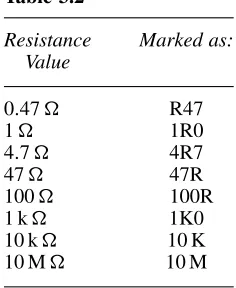
ž determine the resistance and tolerance of a fixed resistor from its letter and digit code
3.1
Resistance and resistivity
The resistance of an electrical conductor depends on four factors, these being: (a) the length of the con-ductor, (b) the cross-sectional area of the concon-ductor, (c) the type of material and (d) the temperature of the material. Resistance, R, is directly proportional to length, l, of a conductor, i.e. R / l. Thus, for example, if the length of a piece of wire is doubled, then the resistance is doubled.
Resistance, R, is inversely proportional to cross-sectional area,a, of a conductor, i.e.R / 1/a. Thus, for example, if the cross-sectional area of a piece of wire is doubled then the resistance is halved.
Since R / l and R / 1/a then R / l/a. By inserting a constant of proportionality into this rela-tionship the type of material used may be taken into account. The constant of proportionality is known as the resistivity of the material and is given the
symbol (Greek rho). Thus,
resistance R= rl
a ohms
is measured in ohm metres (m). The value of the resistivity is that resistance of a unit cube of the material measured between opposite faces of the cube.
Resistivity varies with temperature and some typ-ical values of resistivities measured at about room temperature are given below:
RESISTANCE VARIATION 21
Glass 1ð1010m (or 104µm⊳ Mica 1ð1013m (or 107µm⊳
Note that good conductors of electricity have a low value of resistivity and good insulators have a high value of resistivity.
Problem 1. The resistance of a 5 m length of wire is 600. Determine (a) the
resistance of an 8 m length of the same wire, and (b) the length of the same wire when the resistance is 420.
(a) Resistance,R, is directly proportional to length, l, i.e. R / l. Hence, 600 / 5 m or 600 D ⊲k⊳⊲5⊳, where k is the coefficient of proportionality.
Hence,kD 600
5 D120
When the length l is 8 m, then resistance RDklD⊲120⊳⊲8⊳D960Z Problem 2. A piece of wire of
cross-sectional area 2 mm2 has a resistance of 300. Find (a) the resistance of a wire of the same length and material if the
cross-sectional area is 5 mm2, (b) the cross-sectional area of a wire of the same length and material of resistance 750.
Resistance R is inversely proportional to cross-sectional area,a, i.e.R /l/a
Hence 300/ 12mm 2
or 300D⊲k⊳⊲12⊳,
from which, the coefficient of proportionality, k D
300ð2D600
(a) When the cross-sectional areaaD5 mm2 then
RD⊲k⊳⊲15⊳
D⊲600⊳⊲15⊳D120Z
(Note that resistance has decreased as the cross-sectional is increased.)
(b) When the resistance is 750then
750D⊲k⊳ 1
a
from which
cross-sectional area,aD k
750 D 600 750
D0.8 mm2 Problem 3. A wire of length 8 m and cross-sectional area 3 mm2 has a resistance of 0.16. If the wire is drawn out until its cross-sectional area is 1 mm2, determine the resistance of the wire.
ResistanceRis directly proportional to lengthl, and inversely proportional to the cross-sectional area,a, i.e.
R /l/aorRDk⊲l/a⊳, wherekis the coefficient of proportionality.
Since R D0.16, l D 8 anda D 3, then 0.16 D
⊲k⊳⊲8/3⊳, from whichkD0.16ð3/8D0.06 If the cross-sectional area is reduced to 1/3 of its original area then the length must be tripled to 3ð8, i.e. 24 m
New resistanceRDk
Problem 4. Calculate the resistance of a 2 km length of aluminium overhead power cable if the cross-sectional area of the cable is 100 mm2. Take the resistivity of
aluminium to be 0.03ð106m.
Length l D 2 kmD 2000 m, areaa D 100 mm2
D
100ð106m2 and resistivityD0.03ð106m.
ResistanceRD l
22 ELECTRICAL AND ELECTRONIC PRINCIPLES AND TECHNOLOGY
ResistanceRDl/ahence cross-sectional area
aD l
R D
⊲0.02ð106m⊳⊲40 m⊳ 0.25
D3.2ð106m2
D⊲3.2ð106⊳ð106mm2D3.2 mm2
Problem 6. The resistance of 1.5 km of wire of cross-sectional area 0.17 mm2 is 150. Determine the resistivity of the wire.
Resistance, RDl/ahence
resistivity D Ra
l
D ⊲150⊳⊲0.17ð10
6m2⊳ ⊲1500 m⊳
D0.017×10−6Zm or0.017mZm
Problem 7. Determine the resistance of 1200 m of copper cable having a diameter of 12 mm if the resistivity of copper is
1.7ð108m.
Cross-sectional area of cable,
aDr2 D
12 2
2
D36mm2 D36ð106m2
ResistanceRD l
a
D ⊲1.7ð10
8m⊳⊲1200 m⊳ ⊲36ð106m2⊳
D 1.7ð1200ð10
6
108ð36
D 1.7ð12
36 D0.180Z
Now try the following exercise
Exercise 11 Further problems on resistance and resistivity
1 The resistance of a 2 m length of cable is 2.5. Determine (a) the resistance of a 7 m length of the same cable and (b) the length of the same wire when the resistance is 6.25. [(a) 8.75(b) 5 m]
2 Some wire of cross-sectional area 1 mm2 has a resistance of 20.
Determine (a) the resistance of a wire of the same length and material if the cross-sectional area is 4 mm2, and (b) the cross-sectional area of a wire of the same length and material if the resistance is 32
[(a) 5(b) 0.625 mm2] 3 Some wire of length 5 m and cross-sectional area 2 mm2 has a resistance of 0.08. If the wire is drawn out until its cross-sectional area is 1 mm2, determine the resistance of the wire. [0.32]
4 Find the resistance of 800 m of copper cable of cross-sectional area 20 mm2. Take the resis-tivity of copper as 0.02µm [0.8] 5 Calculate the cross-sectional area, in mm2, of a piece of aluminium wire 100 m long and having a resistance of 2. Take the resistivity of aluminium as 0.03ð106m [1.5 mm2] 6 The resistance of 500 m of wire of cross-sectional area 2.6 mm2 is 5. Determine the resistivity of the wire in µm
[0.026µm] 7 Find the resistance of 1 km of copper cable having a diameter of 10 mm if the resistivity of copper is 0.017ð106m [0.216]
3.2
Temperature coefficient of
resistance
In general, as the temperature of a material increases, most conductors increase in resistance, insulators decrease in resistance, whilst the resistance of some special alloys remain almost constant.
RESISTANCE VARIATION 23
resistor of that material when it is subjected to a rise of temperature of 1°C. The symbol used for the temperature coefficient of resistance is˛(Greek alpha). Thus, if some copper wire of resistance 1 is heated through 1°C and its resistance is then mea-sured as 1.0043then˛D0.0043/°C for cop-per. The units are usually expressed only as ‘per °C’, i.e. ˛ D 0.0043/°C for copper. If the 1 resistor of copper is heated through 100°C then the resistance at 100°C would be 1C100ð0.0043D 1.43 Some typical values of temperature coef-ficient of resistance measured at 0°C are given below:
Copper 0.0043/°C Nickel 0.0062/°C
Constantan 0
Aluminium 0.0038/°C Carbon 0.00048/°C Eureka 0.00001/°C
(Note that the negative sign for carbon indicates that its resistance falls with increase of temperature.) If the resistance of a material at 0°C is known the resistance at any other temperature can be deter-mined from:
Rq=R0.1+a0q/
where R0Dresistance at 0°C
RDresistance at temperature°C
˛0Dtemperature coefficient of resistance at 0°C
Problem 8. A coil of copper wire has a resistance of 100when its temperature is 0°C. Determine its resistance at 70°C if the temperature coefficient of resistance of copper at 0°C is 0.0043/°C.
Resistance R D R0⊲1C˛0⊳. Hence resistance at 100°C,
R100 D100[1C⊲0.0043⊳⊲70⊳]
D100[1C0.301]
D100⊲1.301⊳D130.1Z
Problem 9. An aluminium cable has a resistance of 27at a temperature of 35°C. Determine its resistance at 0°C. Take the temperature coefficient of resistance at 0°C to be 0.0038/°C.
Resistance at °C, R DR0⊲1C˛0⊳. Hence resis-tance at 0°C,
R0 D R
⊲1C˛0⊳ D
27
[1C⊲0.0038⊳⊲35⊳]
D 27
1C0.133
D 27
1.133 D23.83Z Problem 10. A carbon resistor has a resistance of 1 kat 0°C. Determine its resistance at 80°C. Assume that the temperature coefficient of resistance for carbon at 0°C is0.0005/°C.
Resistance at temperature°C,
RDR0⊲1C˛0⊳
i.e.
RD1000[1C⊲0.0005⊳⊲80⊳]
D1000[10.040]D1000⊲0.96⊳D960Z
If the resistance of a material at room tempera-ture (approximately 20°C),R20, and the temperature coefficient of resistance at 20°C,˛20, are known then the resistanceR at temperature°C is given by:
Rq=R20[1+a20.q−20/]
Problem 11. A coil of copper wire has a resistance of 10at 20°C. If the temperature coefficient of resistance of copper at 20°C is 0.004/°C determine the resistance of the coil when the temperature rises to 100°C.
Resistance at°C,
24 ELECTRICAL AND ELECTRONIC PRINCIPLES AND TECHNOLOGY
Hence resistance at 100°C,
R100 D10[1C⊲0.004⊳⊲10020⊳]
D10[1C⊲0.004⊳⊲80⊳]
D10[1C0.32]
D10⊲1.32⊳D13.2Z
Problem 12. The resistance of a coil of aluminium wire at 18°C is 200. The temperature of the wire is increased and the resistance rises to 240. If the temperature coefficient of resistance of aluminium is 0.0039/°C at 18°C determine the temperature to which the coil has risen.
Let the temperature rise to°C. Resistance at°C,
R DR18[1C˛18⊲18⊳]
i.e.
240D200[1C⊲0.0039⊳⊲18⊳] 240D200C⊲200⊳⊲0.0039⊳⊲18⊳ 240200D0.78⊲18⊳
40D0.78⊲18⊳ 40
0.78 D18
51.28D18, from which, D51.28C18D69.28°C
Hence the temperature of the coil increases to 69.28°C
If the resistance at 0°C is not known, but is known at some other temperature1, then the resistance at any temperature can be found as follows:
R1 DR0⊲1C˛01⊳ and R2 DR0⊲1C˛02⊳
Dividing one equation by the other gives:
R1
R2
= 1+a0q1 1+a0q2
where R2Dresistance at temperature2
Problem 13. Some copper wire has a resistance of 200at 20°C. A current is passed through the wire and the temperature rises to 90°C. Determine the resistance of the wire at 90°C, correct to the nearest ohm, assuming that the temperature coefficient of resistance is 0.004/°C at 0°C.
R20D200, ˛0D0.004/°C
and R20
R90 D
[1C˛0⊲20⊳] [1C˛0⊲90⊳]
Hence
R90D
R20[1C90˛0] [1C20˛0]
D 200[1C90⊲0.004⊳]
[1C20⊲0.004⊳]
D 200[1C0.36]
[1C0.08]
D 200⊲1.36⊳
⊲1.08⊳ D251.85Z
i.e. the resistance of the wire at 90°C is 252Z, correct to the nearest ohm
Now try the following exercises
Exercise 12 Further problems on the temperature coefficient of resistance
1 A coil of aluminium wire has a resistance of 50 when its temperature is 0°C. Determine its resistance at 100°C if the temperature coef-ficient of resistance of aluminium at 0°C is
0.0038/°C [69]
2 A copper cable has a resistance of 30 at a temperature of 50°C. Determine its resis-tance at 0°C. Take the temperature coefficient of resistance of copper at 0°C as 0.0043/°C [24.69]