3D VIRTUAL ANASTYLOSIS AND RECONSTRUCTION OF SEVERAL BUILDINGS IN
THE SITE OF SAINT-SIMEON, SYRIA
M. Kurdy a
, J-L. Biscop b, L. De Luca a, M. Florenzano a
a Laboratoire MAP-Gamsau CNRS/MCC (ENSA Marseille), France – (mku, ldl, mfl)@map.archi.fr b
Ministere de la culture et de la Communication (Paris), France - [email protected]
KEY WORDS: 3D scanning, digital model, interactive applications, hypothetical restitution, anastylosis
ABSTRACT:
The site of Qal’at Sem’an, located in the north of Syria, was built in the honor of Saint Simeon around the column on the top of which he lived many years and died in 459. Since 2003, this site has been the object of digital surveys which covered the major part of the area. The sanctuary (Qal’at Sem’an) and the village (Deir Sem’an) are composed of different types of edifices; this variety gives us a large field of studies. Several surveying methods were applied on these sectors according to the morphology of the analyzed parts and to the analysis needs.
This article presents a case study based on a combination of different digital measurement and modeling techniques for the virtual reconstruction of various parts of this complex site. As this work is conducted over several years, different acquisition tools have been experimented for image-based and range-based 3D modeling.
In particular, we focus on the “Residence”, a civil building of the 6th century which probably was an oil mill. We will describe the anastylosis process founded firstly on the digital surveying, secondly on the 3D model structuring and finally on the information interfacing by using NUBES, an integrated platform for describing, analyzing, documenting and sharing digital representations of heritage buildings. The final goal of our work is to evaluate the relevance of the survey / modeling / semantic structuring workflow for an effective analysis of a complex site.
1. INTRODUCTION
The site of Qal’at Sem’an is a large site, built to honor Saint Simeon, and persisted different periods over the years. In the following paragraphs we introduce the site and the French archaeological mission who started years ago ( Figure 1).
1.1 History of the site
Saint Simeon protostylite (before 390-459) won such a reputation that, when dead, his corpse was brought down to Antioch, the capital. The only relic left on the spot was then the column, which remained the goal of an important pilgrimage. Toward the years 470, different buildings for the pilgrims were erected upon the hill where the holy man once lived (Qal’at Sem’an) and in the village of Telanissos (Deir Sem’an). On the hill, a huge cruciform martyrium was built to encapsulate the saint’s column, and on the south side of the hill, a baptistery was erected. Different buildings were progressively displayed around these two poles. Lined by shops, a via sacra connected the holy place to the village. The pilgrim processed from the village, crossing a triumphal arch, and reached a monumental gate with three entrances opened in the surrounding wall. He entered the liturgical yard limited to the south by the baptistery and its church and to the north by the cruciform martyrium. Religious disputes (such as the Sermin massacre of 517) and the Islamic conquest led the pilgrim site into decline. It resumed its activity first under the patriarch Christophoros (966), and twelve years later, with the Byzantine reconquest (978/979), when it was completely fortified. The Arab attacks access to the site in 985 and 1017. After, when the Crusaders invaded the region (1098) on their way to Jerusalem, the monastery has been no more mentioned. Monks were still occupying the site in the middle of 12th century (Sodini 2007)
Figure1. Arian photo for Qal’at sem’an (Y. Guichord CNRS 2001)
1.2 Work background
The new generation of the French mission in Qal’at Sem’an starts to interest about digital tools. The systematic recovery of the topography of the site, including GPS, has broadened the architectural survey to the whole of the sanctuary and the village of Telanissos (current Deir Sem’an).
The access to new technologies has enabled to augment in great measure the spectrum of research and accumulate a large amount of geo-referenced data.
As this site is very wide, a systematic study of three analysis scales corresponding to three phases of data collection were followed to avoid the risk of dispersion: firstly, the topography and architecture of the structures insitu, secondly, comprehensive review of the structures disassembling (block per block) and lastly, the archaeological excavation areas. International Archives of the Photogrammetry, Remote Sensing and Spatial Information Sciences, Volume XXXVIII-5/W16, 2011
These topics give us the possibility to conserve the actual state, to study it and to propose virtual anastylosis.
1.3 Fundamental problem
The architectural studies practiced on the Saint-Simeon site are divided according to the heterogeneity of the field. Diverse methods of acquisition were applied on each case by considering different criteria: shapes surveying, levels of detail, dimensions, excavation stages and dispersed elements. This paper approaches the methodology of 3D reconstruction in three work’s steps (architectural surveying, 3D modeling and information interfacing). Different cases will be exposed, their challenges and suited applications, followed by a detailed study of the “Résidence”.
2. METHODOLOGY OF 3D RECONSTRUCTION
Our work focuses on an integrated approach based on the combination of different methods, which have been applied to the diverse sectors. The main goal of our approach does not focus on the visualization performance, but proposes how to apply 3D visualization tools for an effective architectural analysis.
For each of the three steps (surveying, modeling and semantic structuring), there are a lot of elements helping to define the methodology on the studied object.
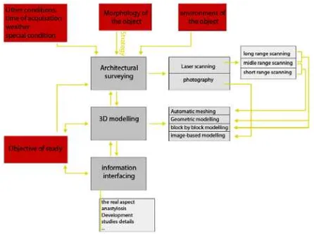
Firstly, the morphology of the object and its environment has an important role in defining the acquisition strategy. In turn, the adopted surveying strategy conditions the three-dimensional data processing and, as a consequence, the way to associate knowledge by information interfacing. Secondly, the analysis needs must be considered during the entire process. Finally, in the first step of the surveying, other elements should be taken into account such as the time available for the acquisition, the weather or the lighting conditions.
The scheme presented in figure 2 describes the strategy, which is the relationship, between the contexts, the conditions and the three steps of acquisition, on one hand, and between the three steps of the 3D reconstruction workflow in another hand.
Figure 2. The 3D reconstruction strategy
The architectural surveying, with its different acquisition types, allows ‘saving’ the actual state in raw data (point clouds, photos and topographical data) able to be treated according to different analysis needs.
In this sense, we do not consider the 3D reconstruction just as a way to represent the actual state of buildings, but as a support for architectural and archaeological studies: it is an interpretation of the building morphology based on reliable data. The choice of the level of detail in the geometric modeling step defines the relevant information that we want to display according to the analysis objective. We base our 3D reconstruction on the approach introduced by (De Luca et al. 2006). Finally, information interfacing with the 3D models allows an effective representation of knowledge that guide the interpretation of surveyed data.
In the following parts, every adopted method is described according to the problems highlighted in the case study: morphology, interpretation of the missing shapes, difficulty of survey, dimensions of the edifices. The cases approached are the cruciform church, the underground cisterns, the moulded blocks, the triumphal arch with the excavation sectors and the surrounding wall.
2.1 The cruciform church
This building is composed of four basilicas disposed in cross form around an octagonal drum centered on the famous column. Its well-conserved shapes constitute now an open space, unroofed walls, with enough space all around to define our stations of scan. A time-of-flight scanner, which scans in long range (between 2-200m), has been used. Its scanning system uses rotating devices for the angular displacement of the laser beam in 360° on the horizontal axe and 70° on the vertical one. For this reason, it is especially useful for public and open areas.
Once the data gathered and geo-referenced in Saint-Simeon system (250 millions of points; this first surveying campaign was carried out by Y. Egels, ENSG), the whole point cloud was cleaned from unnecessary points and sampled. The point cloud was cut into various elements according to the architectonic structure; this process followed the construction logic in order to be consistent with the technique of reconstruction.
Figure 3.The point cloud of the church and the used scanner
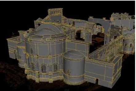
Based on these divisions and on the extracted profiles, a model of description of the building morphology was realized (Figure 3). In this case, the 3D model was done in a simplified way to show important deformations of the edifice without deepening in moulded elements (Figure 4).
Figure 4. The geometric reconstruction
For the semantic description of the building morphology a scene graph was created. It indicates hierarchical relations among individual elements and sub-elements that compose the building (JL. Biscop 2005). According to this structuring method, the church was divided into fifteen groups, each one composed of several entities (figure 5).
Figure 5. The representation for the phase of semantic description of the morphology of the church
The study of the fallen blocks was laid on (dimensions, decoration…) in order to reconstruct the anterior state of the central octagonal drum (JL. Biscop 2010). Starting from this study, a 3D hypothetical reconstruction by image-based modeling was elaborted (Figure 6).
Figure 6. The drum restitution
2.2 The underground cisterns
The site’s location in a region devoid of underground water interposed a system for collecting rainwater and directing it to the cisterns. These were more often related to the extraction of stone, whose quality was better were extracted from deep levels.
In order to survey some of those cisterns, a middle-range (2m-80m) laser scanner was used. It covers a total vision field of 360° on the horizontal and 320° on the vertical and acquires 120.000 points per second (Figure 7).
The choice of this type of scanner depends on the morphology of the cistern; it is a closed space with limited dimensions. There were two kinds of cisterns, single or multi-mouthed cistern. In the case of single mouth, one scan station could cover the entire surface; on the contrary various scans were necessary for the multiple mouths cisterns.
Figure 7. The point cloud of the Exterior baptistery cisterns and the scanner used
3D models have been realized by automatic meshing, as the point clouds were very dense. In this way geometric shapes, which were difficult to model interactively, could be reconstructed (Figure 8).
This step was a real benefice to study each part individually and collectively.
Figure 8. The 3D model of the Lapidarium cisterns
The goal of this reconstruction is to achieve a mapping of rainwater management and define all the canalization systems of the site (Figure 9 and 10).
Figure 9. The canalization system under the west basilica
Figure 10. Cross-sections of the different cisterns surveyed
2.3 Moulded blocks
This site, like most archaeological sites, contains a lot of moulded blocks that are well conserved and important for the comprehension of the architecture.
Those elements have been surveyed using a short-range scanner based on optical triangulation which acquires both shapes and textures with millimetric precision. It is a short-range scanner (0.50-2.50 m) very sensible to light. For scanning with this laser, the artificial lighting is preferable to the natural one. That restricts the type of surveyed objects.
The point clouds of each element were automatically meshed and then assembled in polygonal representation containing from 100.000 to 400.000 polygons (Figure 11).
Figure 11. The high definition survey of the top block of the baptistery basin and the used scanner.
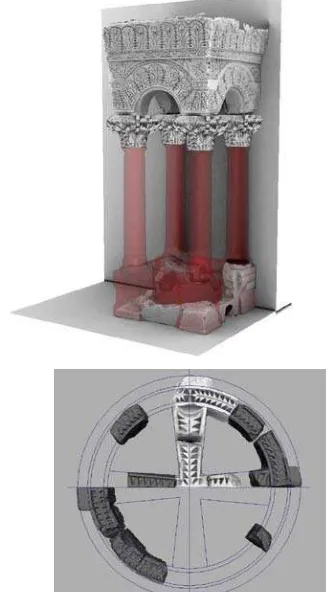
For the visual enrichment of the 3D meshes, we used an ambient occlusion algorithm similar to (Duguet et al. 2004). The collected surveyed elements allowed us to analyze in detail their characteristics and to develop a virtual anastylosis according to the observed shapes, (figure 12).
Figure 12. Anastylosis of tow cases: the baptistery basin and its canopy (up) and the oculus of the western basilica (down).
2.4 The triumphal arch with the excavations sectors
The actual road between the village and the sanctuary of Saint-Simeon is commonly linked to the ancient sacred way. It starts with a triumphal arch with ruins of buildings situated in both sides of the gate. In these sectors, excavations started few years ago (figure 13).
The surveying of this complex focused firstly on the arch and secondly on the excavated sectors. We surveyed some excavation stages in different times. According to scale and morphology of this part, a long-range scanner was used for the surveying.
Figure 13. The triumphal arch and shops International Archives of the Photogrammetry, Remote Sensing and Spatial Information Sciences, Volume XXXVIII-5/W16, 2011
The 3D model has been realized lying on the point cloud, according to architectural rules. In the case of the arch, the point cloud was coupled with sets of photographs; in contrariwise for the excavation sector, the model was reconstructed block by block (figure 14). The photographs were matched on the 3D model (extracted from the point cloud by an interactive modeling procedure) by a spatial resection algorithm (Tsai 1986).
This part of the complex was reconstructed by two different techniques according to two different needs: on one side, the realistic reconstruction obtained by photo-based texture mapping, on the other side, the archaeological analysis of the excavations carried by the detailed modeling, block by block (Figure 14).
Figure 14. The 3D model of the arch and excavated area
2.5 The surrounding wall
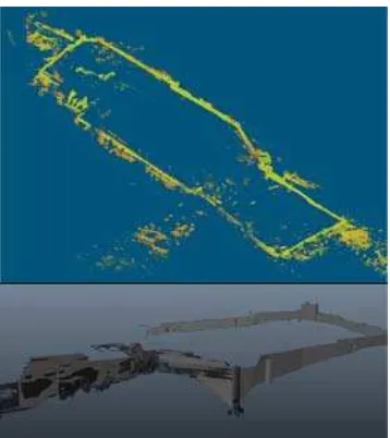
The sanctuary situated on the hill (Qal’at sem’an) is surrounded by a wall built in the 5th century and fortified in the 10th century (Biscop 2006). It is actually an open space 400m long, 100m large, a long-range scanner was chosen for it surveying.
Figure 15. The point cloud of the surrounding wall and its 3D model.
The 3D model was based on the point cloud and realized by interactive modeling using simple geometrical primitives. In this case, the obtained 3D representation was necessary firstly to document the actual state of the wall and secondly to analyze the site’s morphology at different scales (figure 15).
The comprehension of the morphology of the general site and the relation between parts and sub-parts with the unit are
essential in order to study how to place each piece of the puzzle correctly and relatively to its neighbors.
Large sites are generally composed by entities with different morphological complexities and have undergone several modifications over time such as damages or restorations. Our approach combines different tools and techniques in order to give a good support for the analysis of this complex study.
3. RECONSTRUCTION AN ANASTYLOSIS OF “THE RESIDENCE”
The “Residence” is a remarkable edifice in the village of Telanissos (Deir Sem’an), located in the south west of the sanctuary (figure 16). It’s a civil building of the 6th century, well preserved, and it consists of a main entrance, a courtyard, and a two-storey building. It probably was an oil mill. Clandestine excavations, made recently under the central arch, discovered a huge wheel frame, necessarily installed before or during the construction, and fixed in the centre of this arch.
Figure 16. Plan of the site (Tchalenko, 1953-1958)
In the following paragraphs, we will describe the development of an anastylosis founded on several surveying and modeling techniques.
3.1 Architectural surveying
During the campaign of 2008, an architectural surveying was carried out focusing on three main objectives. The first was to collect and assemble metric information concerning shapes and dimensions of the studied object. The second was to acquire photographical information to visually enrich (by means of textures) all the conserved elements (actually in their original place). The third one was to acquire photographic information concerning all elements and blocks displaced in time.
3.1.1 Metrical surveying
A time of flight laser scanner was used for the metrical surveying of the main building and the rest of the court. The choice of this scanner depended on the state of the building: it does not contain close spaces and it allows the acquisition from International Archives of the Photogrammetry, Remote Sensing and Spatial Information Sciences, Volume XXXVIII-5/W16, 2011
an appropriate distance. The result surveying was a point cloud geo-referenced in the global topographical system of Saint-Simeon site.
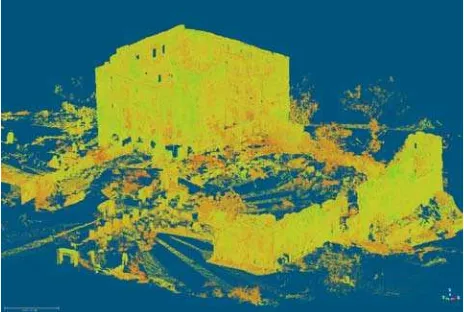
The point cloud’s density is near to one point per 5 millimeters. Ten stations were necessary to survey the entire building. After the registration step, the result was a 25.5 millions co-ordinates point cloud (figure 17).
Figure 17. The final point cloud of the “Résidence”.
3.1.1 Photographical acquisition on surfaces
The objective of the photographic acquisition was to obtain accurate visual information of the actual state. That’s a very important aspect not only for the visualization purpose but also for the analysis of details that we couldn’t reconstruct in a general 3D model. Digital cameras with 12 megapixels sensors and different lenses (18 mm - 70 mm) were used.
A set of images covered the totality of the building surfaces. Other photos compensate on the lack of information present in the point cloud, obtained by laser scanning (figure 18).
Figure 18. Photo acquisition for texture application.
3.1.3 Photographical acquisition on blocks
The aim of this task was to make a collection of photos recovering the shape and the visual appearance of each block related to the destroyed parts of the building. Photos are used to reconstruct the geometry of the most significant blocks by image-based modeling (figure 19).
Because of the flexibility in the acquisition phase, photographical technique has been used for the surveying of all blocks that will not be removed from the site. This kind of acquisition is faster than laser scanning and can save a great amount of information.
Figure 19. Collection of photos for the basin in court of the “Résidence”.
3.2 Geometric reconstruction
All data collected during the different surveys was used for a general three-dimensional reconstruction. A specific data processing was experimented for each type of entity.
3.2.1 Range-based modeling
Concerning the parts still in their original place the 3D reconstruction was realized basing on relevant profiles extracted from the point cloud.
With the aim of analyzing the building’s morphology, we built a block by block 3D model tacking into account also fissures and displacements.
3.2.2 Image-based modeling
Even if positions and general shape of the dispersed blocks were present into the point cloud, in order to reconstruct in accurate way their shape we used the image-based-modeling technique. That allowed us a detailed and textured reconstruction of a set of entities ready to be virtually relocated in their hypothetical position into the building’s morphology (figure 20). This technique is based on three main steps exploiting photographs: the camera calibration and orientation, the geometrical modeling and the texture mapping.
Figure 20. Te 3D model of the basin in court yard
3.3 Visual enrichment
In order to realize a 3D model with a realistic appearance, a layer of photographic information has been projected on the 3D model. The acquired photographs was oriented on the 3D model and mapped on surfaces. The main objective was to visualize all details we could not display in normally shaded model. This International Archives of the Photogrammetry, Remote Sensing and Spatial Information Sciences, Volume XXXVIII-5/W16, 2011
step allowed us to build a visually rich reconstruction of the ‘Résidence’.
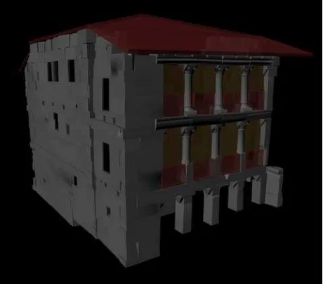
Several 3D elements realized by different techniques were integrated according to the geo-referenced co-ordinates system in order to reconstruct the context in wich the “Residence” is situated (figure 21).
Figure 20. The 3D reconstruction of the actual state of the ‘Résidence’
3.4 Virtual anastylosis
This geometric reconstruction was the starting point for the analysis and the development of the virtual anasytlosis.
The first phase consisted in the systematic study of the morphology and the dimension of the blocks already surveyed in order to figure their original locations. An attentive observation of the building, the existing parts and the missing ones, has be done too (Biscop 1999)
Moreover, a lot of blocks are dispersed from the site, in reason of reuse or displacement for natural causes, making necessary to compare the building characteristics with similar edifices in this region. This study allowed a first hypothetical restitution (figure 22).
Figure 22. The anastylosis of the ‘Résidence’.
3.5 Information interfacing by NUBES:
The 3D reconstruction of an architectural building presents a high level of information (metrical, geometrical, visual, etc.). We work actually on the possibility to enrich this representation by means of an information system called (Nubes). It’s an
integrated platform for describing, analysing, documenting and sharing digital representations of edifices. Many types of information could be associated to the 3D model (dimensional, morphological, historical and descriptive) so to be accessible on the web to the professionals and general public.
This information system consists of a Web application based on a three-part architecture:
• A database, developed in MySQL, organizing the raw surveying data, the multiple representations obtained from processing (3D models) and the documentary sources (2D iconography);
• An interactive 3D scene developed in Virtools DEV allows the downloading, the visualisation and the handling of 3D representations;
• A set of PHP pages which facilitates the user’s access to stored information and provides the necessary footbridges for the dialogue between the 3D scene and the data base.
The geometric model was support for the anastyosis, in this sense; it could be interesting to associate to the geometrical representation all documents used for this study. In fact, the Nubes platform is a tool that architects and archaeologists can use in order to spatialize, qualify and share heterogeneous information around the study of the building’s morphology.
4. CONCLUSION:
This article described a project that focus on several aspects : architectural surveying, geometrical modeling, hypothetical reconstruction and information interfacing.
In this work, we highlighted several limits and perspectives. Concerning limits, the discussed acquisition techniques collect a great amount of data, witch makes the visualization of the entire site very difficult. In this case, the semantic structuring allowed us to solve this problem and to realize a geometric representation of the site according to an architectural point of view.
Concerning perspectives, the next step will focus on linking all collected data with documentary sources by using the Nubes platform. We believe that linking documentary sources to the morphology representation is an essential step in order to document a complex site like Saint-Simeon.
5. ACKNOWLEDGEMENTS
The experiences presented in this paper are the result of several studies aimed during different archaeological missions from 2003 to 2010. Authors want to acknowledge all the participants contributing to this mission, especially for the survey and 3D modeling: Y. Egels, D. Schelstraete, J. Deléglise, M. Deveau, L. Mauranges.
6. REFERENCES:
Biscop, J.L, 2006. The "Kastron" of Qal'at Sem'an, in H. Kennedy éd. Muslim Military architecture in Greater Syria, Brill, Leyde, p. 75-83.
Biscop, J.L, 2005. Le chantier du martyrium de Saint-Syméon: du dessin à la mise en œuvre, in Mélanges Jean-Pierre Sodini, Travaux et Mémoires 15, p.11-36.
Biscop, J.L, 2010. The Roof of the Octagonal Drum of the International Archives of the Photogrammetry, Remote Sensing and Spatial Information Sciences, Volume XXXVIII-5/W16, 2011
Martyrium of Saint-Symeon, in Falko Daim und JÖrg Drauschke (Hrsg.), Byzanz - das Römerreich in
Mittelalter, Teil 2,2 Schauplätze, Mainz, p. 692-879.
De Luca, L., Véron, P. & Florenzano, M., 2006. Reverse engineering of architectural buildings based on a hybrid modeling approach. Computers & Graphics, p.160-176.
Duguet, F. et al., 2004. A Point-Based Approach for Capture, Display and Illustration of Very Complex Archeological Artefacts. in The 5th International Symposium on Virtual Reality, Archaeology and Cultural Heritage. VAST, p. 105-114.
Biscop, J., 1999. Deir Déhès. Monastère d'Antiochène, Syria, p. 14-33, 131-181.
Sodini, J., 2007. Saint-Syméon, lieu de pèlerinage. in Les cahiers de Saint-Michel de Cuxa, (38).
Tsai, R., 1986. An efficient and accurate camera calibration technique for 3d machine vision. Dans IEEE Conferance on Computer Vision an Pattern
Recognition. Miami Beach, FL, p. 346-374.
NUBES, www.map.archi.fr/nubes