accredited by DGHE (DIKTI), Decree No: 51/Dikti/Kep/2010 355
Performance of Channel Estimation in MIMO-OFDM
Systems
Subuh Pramono1, Eddy Triyono2
Department of Electrical Engineering, Politeknik Negeri Semarang Jl. Prof Soedharto, Tembalang, Semarang, Indonesia e-mail: [email protected],[email protected]
Abstrak
Paper ini mensimulasikan kinerja metode estimasi kanal fading pada orthogonal frequency division multiplexing-multiple input multiple output (OFDM-MIMO), least squares (LS) dan minimum mean squared error (MMSE). Channel impul response (CIR) kanal fading dibutuhkan untuk mengatasi intersymbol interference (ISI). Informasi channel impul response didapat dari estimasi kanal. Iterasi simulasi menggunakan teknik monte-carlo untuk menghasilkan kinerja bit error rate (BER) dan mean squared error (MSE). Hasil simulasi menunjukkan bahwa mean squared error pada sistem MIMO lebih baik dibanding sistem SISO. Dengan estimasi kanal MMSE, sistem MIMO 2Tx-2Rx memberikan perbaikan ±2 dB dibanding sistem SISO untuk nilai MSE 10-2.Selanjutnya, Sistem MIMO 3Tx-2Rx menghasilkan perbaikan 1.5 dB dan MIMO 4Tx-2Rx menghasilkan 3.5 dB. Pada sistem MIMO 2Tx-Rx, teknik estimasi kanal MMSE menghasilkan kinerja lebih baik ±1 dB dibanding teknik estimasi kanal LS untuk untuk MSE 10-2 dengan nilai signal to noise ratio (SNR) yang cukup besar. Penyusunan pilot, block type-pilot menghasilkan kinerja lebih baik dibanding comb pilot untuk kondisi kanal fading cepat. Block type-pilot memperbaiki sistem ±10 dB dibanding comb type-type-pilot dengan teknik MMSE untuk nilai BER 2 10-2.
Kata kunci:block-comb type, LS, MIMO-OFDM, MMSE
Abstract
This paper presented the performance of faded channel estimation method on orthogonal frequency division multiplexing-multiple input multiple outputs (OFDM-MIMO) i.e. least squares (LS) and minimum mean squared error (MMSE). Channel impuls response (CIR) was required to overcome the intersymbol interference (ISI). Channel impuls response information was obtained from channel estimation processing. Iterance simulation used monte-carlo technique to determine the performance of bit error rate (BER) and mean squared error (MSE). Simulation results show that the mean squared error performance on MIMO system was better than the SISO system. On MMSE channel estimation, the MIMO 2Tx-2Rx system provided ± 2 dB improvement that compared to SISO system at value of MSE 10
-2.Furthermore,MIMO 3Tx-2Rx produce improvement about 1.5 dB, MIMO 4Tx-2Rx improve about 3.5 dB
at BER 10-4,respectively.The MIMO 2Tx-2Rx system, MMSE channel estimation produced better performance ± 1 dB than LS channel estimation with sufficient SNR value for MSE 10-2.Pilot arrangement, the simulation results show that the block type-pilot arrangement produced better performance than the comb type-pilot arrangement at fast fading channel. Block type-pilot arrangement system produced better ± 10 dB than the comb type-pilot arrangement with MMSE method at value of BER 2 10-2.
Keywords: block-comb type, LS, MIMO-OFDM, MMSE
1. Introduction
The combination of orthogonal frequency division multiplexing (OFDM) with multiple input multiple-output (MIMO) and space-time coding has received much attention recently to combat multipath delay spread and increase system capacity. However, to use the advantages that MIMO systems can offer, accurate channel state information (CSI) is required at the transmitter and/or receiver. Channel state information is needed in order to coherently decode the transmitted signal [3].
bits, which is unique for a certain transmitter and which is repeated in every transmission burst. Thus, the channel estimator is able to estimate CIR for each burst separately by exploiting the known transmitted bits and the corresponding received samples. There are a few different approaches of channel estimation, like Least-squares (LS) or Linear Minimum Mean Squared Error (LMMSE) methods [6].
Optimal placement and energy allocation of training symbols or pilot for both single-carrier and OFDM systems were considered in [7] for frequency-selective block-fading channel estimation. For OFDM systems, the optimal placement of pilot is equal spacing in the frequency domain. In [5], optimal design and placement of pilot symbols for frequency-selective block-fading channel estimation are addressed for single-input single-output (SISO) as well as multiple-input multiple-output (MIMO) [2].
Time
F
re
qu
en
cy
block
Time
F
re
qu
en
cy
Data Pilot
a. Block-type pilot channel estimation b. Comb-type pilot channel estimation Figure 1. Two basic types of pilot arrangement [10]
2. System Model
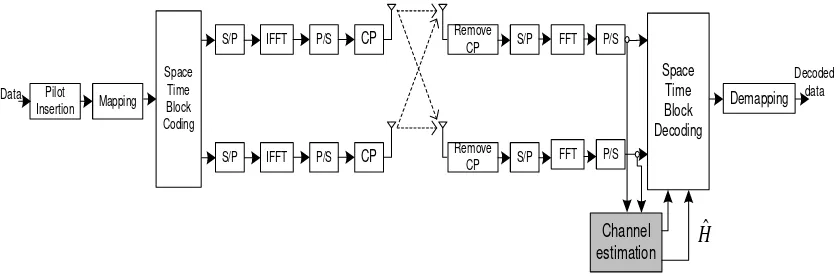
This paper explains the performance of channel estimation in MIMO-OFDM system. This research explores the MIMO 2 Tx, 3 Tx, and 4 Tx respectively.
Pilot Insertion
S/P IFFT CP
IFFT CP
Remove CP
Remove CP
FFT
FFT
Space Time Block Decoding
Channel estimation
Demapping
Decoded data Data
H
ˆ
S/P P/S
P/S S/P
S/P
P/S
P/S Mapping
Space Time Block Coding
Figure 2. MIMO 2 x 2 system description
The output of the encoder is then split into two ways, one for each antenna as described for the simple case of MIMO space-time coding in [8]. From [8] applied for the OFDM system, we can have the following vectors for antennas 1 and 2 with full rate:
X =
X
X
X
X
...(1)X
21= X
1
-X
2*X
3-X
4*,
…
., X
N-1-X
N* ...(2)X
22= X
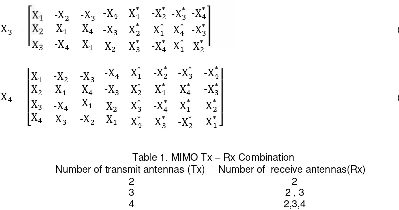
The following complex transmission matrixes of size MT (number of transmit antennas) = 3 and 4 respectively incorporating a code rate of 1/2.
X
3=
X
1-X
2-X
3X
2X
1X
4X
3-X
4X
1-X
4X
1*-X
2 *
-X
3X
2*X
1*X
2X
3*-X
4*-X
3*X
4*X
1*-X
4*-X
3*X
2*...(4)
X
4=
X
1-X
2-X
3X
2X
1X
4X
3X
4-X
4X
3X
1-X
2-X
4X
1*-X
2*-X
3X
2*X
1*X
2X
1X
3*X
4*-X
4*X
3*-X
3*-X
4 *
X
4*-X
3 *
X
1*-X
2*X
2*X
1*...(5)
Table 1. MIMO Tx – Rx Combination
Number of transmit antennas (Tx) Number of receive antennas(Rx)
2 2
3 2 , 3
4 2,3,4
Minimum mean-square error (MMSE) estimator has good performance but high complexity. Least square [LS] estimator has low complexity, but its performance is not good as that of the MMSE estimator. We use the assumption of a finite length impulse response and QPSK modulation. The performance is presented both in terms of mean-square error (MSE) and bit error rate (BER).
The LS estimator minimizes the parameter Y-XH H Y-XH where ( )H means the conjugate transpose operation. It is shown that the LS estimator ofHis given [10].
HLS= X-1Y= Xk Yk
T
(k=0,…,N-1)... .(6)
The MMSE estimator employs the second-order statistics of the channel conditions to minimize the mean-square error. Denote byRgg,RHH, andR the auto covariance matrix of g,H, andY. RgY is the cross covariance matrix between g and Y,also denote by N2 the noise variance E N2 . Assume the channel vector gand the noiseNare uncorrelated, it is derived that
RHH= E{H HH} = E Fg Fg
H
= F RggFH... (7)
RgY= E g Y
H
= E g X Fg+ N
H
= RggFHXH... (8)
Ryy= E Y Y
H
= X F RggFHXH+ σN2IN... (9)
AssumeRgg(thusRHH) andσN2 are known at the receiver in advance, the MMSE estimator ofgis
given by gMMSE= RgYRYY -1
YHH[10]. Note that if g is not Gaussian, gMMSE is not necessarily a minimum mean-square error estimator, but it is still the best linear estimator in the mean-square error sense. At least, it is calculated that
HMMSE= FgMMSE= F FHXH -1R
gg -1
σN2+ XF
-1
Y...(10)
= F Rgg FHXHX F
-1
= RHH RHH+ σN2 X XH -1 -1
HLS...(12)
The MMSE estimator yields much better performance than LS estimator, especially under the low SNR scenarios. A major drawback of the MMSE estimator is its computational complexity, especially if matrix inversions are needed each time the data inXchange.
Orthogonality principle is main subject in orthogonal frequency division multiplexing, as follows [1] [9]:
φl( t) φk*
b
a
( t) dt= Ek, if l= k
0, if l≠ k
= Ekδ l-k ...(13)
Ss( kT) =
1
N ∑ Ane
( jφn)ej ( n∆ω) kT
N-1
n= 0 ...(14)
OFDM signal equation is equal to discrete fourier transform equation:
Ss( k) = 1
N ∑ S( n) e
j 2πnkN
N-1
n= 0 ...(15)
In other side, demodulation process uses discrete Fourier transform equation, as follows:
Ss( m) = ∑
1
NS( n) ∑ e
j 2π( n-m) kN N-1
n= 0 N-1
k= 0 ...(16)
Ss( m) = ∑ S( n) δ n-m
N-1
k= 0 ...(17)
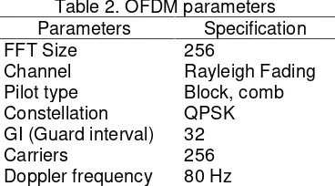
Table 2. OFDM parameters Parameters Specification
FFT Size 256
Channel Rayleigh Fading
Pilot type Block, comb
Constellation QPSK
GI (Guard interval) 32
Carriers 256
Doppler frequency 80 Hz
3. Results and Analysis
This paper observe both multiplexing diversity gain and spatial diversity gain on MIMO system these are described by both mean squared error and bit error rate performance. This simulation uses monte-carlo method for generating both MSE and BER performances.
3.1. SISO and MIMO Performances
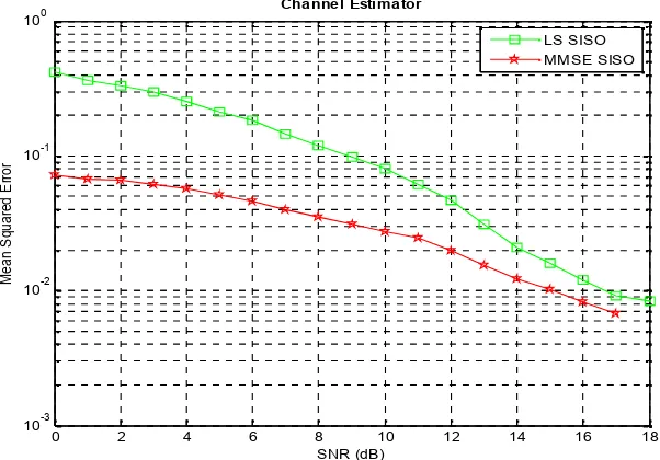
Figure 3 depicts the mean squared error performance of the channel estimator on SISO system, MMSE channel estimator gives a better performance than the LS channel estimator. However, this advantage must be compensated by the complexity of the calculation and knowledge of the channel.
correlations matrix. The better MIMO performance yielded by spatial multiplexing on transmitter system and spatial diversity on receiver system.
Figure 3. MSE performance on single input single output system
Figure 4. MSE performance on MIMO 2 x 2 system
3.2. Performance of Block and Comb Type - Pilot Arrangement
Figure 5 and figure 6 show the BER performance on both block and comb type pilot arrangement on MIMO 2 Tx. Block type – pilot arrangement gives a better performance than the comb type-pilot arrangement. MMSE channel estimator with block type-pilot arrangement produces about 10 dB better than comb type-pilot arrangement at BER 2.0 10-2, the same results also yielded on LS channel estimator system that the block type-pilot arrangement gives the better BER performance than comb type-pilot arrangement. This is due to fast fading that the channel is rapidly changing. The block-type arrangement can compensate the fading.
0 2 4 6 8 10 12 14 16 18
10-3 10-2 10-1 100
SNR (dB)
M
ea
n
S
qu
ar
ed
E
rr
or
Channel Estimator
LS SISO MMSE SISO
0 2 4 6 8 10 12 14 16 18
10-3 10-2 10-1 100
SNR (dB)
M
ea
n
S
qu
ar
ed
E
rr
or
Channel Estimator
Figure 5. BER performance on block type – pilot arrangement with MIMO 2 Tx
Figure 6. BER performance on comb type – pilot arrangement with MIMO 2 Tx
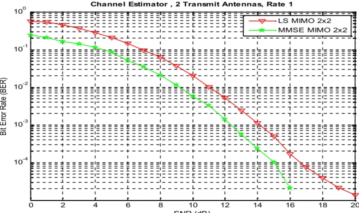
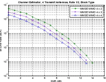
Figure 7 and figure 8 describe the BER performance of MIMO 3 Tx and 4 Tx with combination number of receive antennas (Rx). In this section, we determine using MMSE method and block-type arrangement, these have proven that produce a better performance than another method.
0 2 4 6 8 10 12 14 16 18 20
10-4 10-3 10-2 10-1 100
SNR (dB)
B
it
E
rro
r R
at
e
(B
E
R
)
Channel Estimator , 2 Transmit Antennas, Rate 1
LS MIMO 2x2 MMSE MIMO 2x2
0 2 4 6 8 10 12 14 16 18 20
10-2 10-1 100
SNR (dB)
B
it
E
rr
o
r
R
a
te
(
B
E
R
)
Channel Estimator, 2 Transmit Antennas, Rate 1
Figure 7. BER Performance on MMSE method with MIMO 3 Tx
Figure 8. BER Performance on MMSE method with MIMO 4 Tx
Based on Figure 7 and Figure 8, the MIMO 3 Tx and 4 Tx produce significantly improvement. The MIMO 3Tx – 2Rx yield a better performance about 1.5 dB than MIMO
2Tx-0 2 4 6 8 10 12 14 16 18
10-6 10-5 10-4 10-3 10-2 10-1 100
SNR (dB)
B
it
E
rr
o
r
R
a
te
(
B
E
R
)
Channel Estimator,3 Transmit Antennas, Rate 1/2 ,Block Type
MMSE MIMO 3x2 MMSE MIMO 3x3
0 2 4 6 8 10 12 14 16
10-6 10-5 10-4 10-3 10-2 10-1
SNR (dB)
B
it
E
rr
o
r
R
a
te
(
B
E
R
)
Channel Estimator, 4 Transmit Antennas, Rate 1/2, Block Type
2Rx at BER 10-4.Furthermore, the MIMO 4Tx-2Tx produces the best performance. The MIMO 4Tx-2Rx gives advance about 3.5 dB than 2Tx-2Rx at BER 10-4. Higher number transmit antennas produce a bigger spatial multiplexing gain. Furthermore, higher number of receive antennas give a higher spatial diversity gain.
4. Conclusion
MMSE channel estimator produces a better performance than LS channel estimator. However, the complexity of the calculation must be considered. Relying on both spatial multiplexing gain and spatial diversity gain, the MIMO system yields a better performance than the SISO system. The last point, block type-pilot arrangement produces a better BER performance than comb type-pilot arrangement on fast fading channel.
References
[1] Dušan Matiæ. OFDM as a possible modulation technique for multimedia applications in the range of mm waves. Introduction to OFDM. II edition.10/30/98/TUD-TVS.
[2] Hlaing Minn, Naofal Al-Dhahir.Optimal Training Signals for MIMO OFDM Channel Estimation.IEEE Transaction on Wireless Communications. 2006; 5(5): 1158- 1168.
[3] Jianxuan Du, Ye (Geoffrey) Li.MIMO-OFDM Channel Estimation based on Subspace Tracking. The 57th IEEE Semiannual Vehicular Technology Conference (VTC 2003-Spring). Jeju, Korea. 2003; 2: 1084 – 1088.
[4] Kala Praveen Bagadi, Susmita Das. MIMO-OFDM Channel Estimation using Pilot Carries. International Journal of Computer Applications.2010; 2(3): 81-88.
[5] M Dong and L Tong. Optimal design and placement of pilot symbols for channel estimation. IEEE Trans Signal Processing. 2002; 50(12): 3055-3069.
[6] Markku Pukkila. Channel Estimation Modeling. Nokia Research Center. 2000.
[7] S Adireddy, L Tong, H Viswanathan. Optimal Placement of Training for Frequency-Selective Block-Fading Channels.IEEE Trans Info Theory. 2002; 48(8): 2338-2353.
[8] SM Alamouti. A simple transmit diversity technique for wireless communications. IEEE Journal on Selected Areas in Communications.1998; 16: 1451-1458.
[9] Subuh Pramono, Sugihartono. The Performance of Turbo Coded Orthogonal Frequency Division Multiplexing in Rayleigh Fading Channel. International Conference on Instrumentation, Communication, Information Technology and Biomedical Engineering (ICICI-BME). Bandung. 2009: 1-6.