DOI: 10.12928/TELKOMNIKA.v12i4.977 1113
Development of Wireless Electric Field Mill for
Atmospheric Electric Field Observation
Muhammad Abu Bakar Sidik*1,2, Hamizah Shahroom1, Zolkafle Buntat1, Yanuar Zulardiansyah Arief1,Zainuddin Nawawi2, Muhammad ‘Irfan Jambak2 1
Institute of High Voltage and High Current (IVAT), Universiti Teknologi Malaysia, 81310 UTM Johor Bahru, Malaysia
2
Department of Electrical Engineering, Faculty of Engineering, Universitas Sriwijaya, Indonesia *Corresponding author, e-mail: [email protected]
Abstract
Rotating-vane electric field mill (REFM) sensor is one of the popular methods to measure atmospheric quasi-static electric field. Lightning incident occasion can be predicted by observing electric fields strength in atmosphere. In this paper an integration of REFM with an online wireless data monitoring system for long distance observation and data collection is presented. This method reduces the required man-hour to gather data from the REFM as well as system costs by removing the computer and data logger on-site. The development includes hardware and software design in order to improve efficiency the atmospheric electric field measurement system. The contribution of this work is the design of the electronic circuit which converts the ac signal from the REFM sensor to dc signal and then correlates the signal to the electric field strength in the vicinity. Subsequently the information is transmitted via a wireless data transmission system, using the Global System Mobile Communication (GSM) network. Using the proposed method, all the data from sensors can be observed and analysed immediately from any location.
Keywords: atmospheric; electric field sensor; lightning; wireless data communication
1. Introduction
It is a well know fact that the knowledge of ambient electric field strength provides valuable information about the lightning incident. Observation and measurement of atmospheric quasi-static electric field is able to provide lot information regarding to thunder storm activities, lightning incidence, aerosol presence in air, radioactive pollution, indication of earthquakes, and parameters of the solar wind [1]. According to Jacobson [2] when the electric field strength due to the presence of clouds is over the limit of ambient air insulation threshold lightning will occur. The range generally is from 1 kV/cm to 4 kV/cm or within an average of 3 kV/cm.
In order to measure the ambient electric field strength or potential gradient various methods have been introduced [3]; one of which is the electric field mill (EFM) technique. However, in certain circumstances the rotating-van electric field mill (REFM) is generally being used as an instrument for observing the cloud electrostatic phenomena. The principles of operation and location determination of REFM are being widely studied by many authors [4-8]. Typically REFM has to be coupled with a personal computer (PC) on site in order to collect and store data from the instruments [9]. This condition demands costs on installation of computer and data logger system on site, as well as manpower to collect data from REFM sensor location. Furthermore, this also raises safety issues on the instruments and the computer system. Therefore, there should be a solution to be introduced to overcome this problem.
Since most of the sensors located far apart in remote areas, one of the competent technologies that can be applied to this problem is by using wireless data transmission system to transmit data from the REFM to a computer in a data centre building via internet protocol and web-base programming.
Global system for mobile communication (GSM) is the most suitable technology to be applied. GSM is on the market for a long time and it is offering varieties of features and having users of more than 5 billion people, more than 80% of earth population. In addition, GSM is offering low cost ownership and worldwide coverage as this technology has been existed for more than 20 years [10]. However, GSM has several shortcomings, which it is unable to perform transmitting and receiving data concurrently and the unsatisfactory real-time ability [11].
general packet radio service (GPRS) network. GPRS is a packet data technology based on GSM that support both Point-to-Point Protocol, PPP and Internet Protocol, IP, it provides a shorter time for internet service provider connections and the charging will be based on the amount of data sent instead of connection time. With the added packet-switching protocols, it will break the voice or data information into packets which only few kilobytes each. Then, based on addressing data within the packet, the information will be routed by network between different destinations. As compared to GSM, GPRS has high transmission rate, ability to transfer real-time data, supporting internet protocol, IP and having the ability to access the internet [12].
An application of GSM/GPRS modem in atmospheric electric field measurement was revealed by Fort, A. [1], where it was used to access data in the internal memory of the electric field device. However information about the hardware and circuit is not clearly described.
In this paper, detail explanation of a new REFM sensor as well as wireless network data acquisition system using GPRS network designed and built at the Institute of High Voltage and High Current (IVAT) is advances. It is an economical and effective system. By using this technology data collected from remote REFM sensors could be transmitted to a computer in a data centre that is connected internet with a fixed IP address.
2. Instrument Design
2.1. Casing and Sensing Plate
The REFM is an induction field meter with which the ambient electric field strength can be measured. This instrument has a grounded rotating-plate positioned above a sensor plate. When the rotating-plate turns, and the sensor plate will be alternately exposed to and shielded from the induction field; an AC signal will be generated on the sensor plate because of that continuing process.
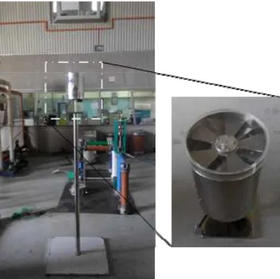
The depiction of the developed REFM is given in
Figure 1. A 12 V DC motor installed inside the chamber was attached to the rotating-plate. The application of dc motor for REFM is more efficient in term of its price and controlling unit when compared to other motors. The rotating-plate and the sensor plate are identical in dimension and shape. Then to fasten the rotating-plate on the motor shaft a special coupling unit was designed. The clearance between the motor chamber and the sensor plate as well as between the sensor and the rotating-plate is 1-cm.
Material selection is an important thing to consider since the REFM will be placed outdoors. Considering the harsh outdoor vicinity the original stainless steel material is selected due to its corrosion-free and tough.
2.2. Signal Processing
The signals generated from the sensor plate must be processed to obtain better quality of electrical signals. The signal processing system involved amplification, filtering, converting, and harmonization. Meanwhile, the amplification unit is integrated with the filtering, converting, and harmonization part.
2.2.1. Signal Amplification
The induced-voltage on the sensor plate is weak to be processed directly therefore a signal amplification unit is needed. Three-stage signal amplification system is developed with the total amplifications are about one-thousand times.
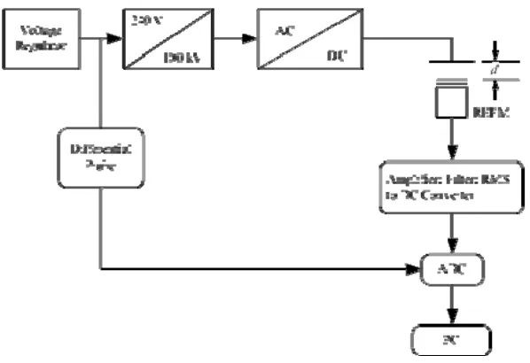
This amplification part is energized with a 12 V DC dual polarity regulated power supply. The DC regulated output supply is obtained from 240 V AC main, through several stages. Firstly, the main AC voltage is connected to a step-down transformer 240/24 V and secondly the rectification of the step-down voltage using bridge rectifier. The bridge rectifier used is single phase 6-A RS68 full-wave rectifier. To obtain a smooth DC output an electrolyte capacitor 1000-μF is used. However, this DC output still has some ripples. Therefore, IC regulators are used to maintain a constant DC ±12 V. The IC regulator 7812 (positive polarity) and 7912 (negative polarity) are used, while the 100 F electrolyte and 0.1 F ceramic functioned as smoothing capacitor.
For signal amplification, operational amplifier LM358 is utilised. The inverting constant multiplier is applied to obtain a precise 3 (three) stage amplification process which is the A = 1000. The adjustment of amplification for each stage employs 500 kΩ trimmer resistors. A low-pass frequency active filter is put after amplification stages to eliminate noise. However, a high impedance circuit has been formed. The high impedance circuit can be decreased by means of a follower circuit – input signal and output signal have the same value.
The original signal from REFM has a fundamental frequency, . Hz with order of noise in kilohertz. The function of the original signal is . . ° . To obtain a better signal, the original signal has to be filtered.
2.2.2. Signal conditioning
The aim of filtering is to remove unwanted noises and pick up selected parts of the signal harmonic. In this work the filter is of a first-order passive low-pass filter which is installed after the amplification unit.
Transfer Function of first-order passive low-pass filter is given in Eq. 1
(1)
For the circuit the maximum value of is 1 (at , therefore the cutoff frequency is
(2)
The filter reduces the magnitude of the signal and causes delay on the original signal. The low-pass filter output is . ° . Therefore at the cutoff frequency the magnitude of input and output voltage relationship can be written as . .
The input voltage is an important consideration to IC AD536 – excessive input voltage will damage the AD536. AD536 is a complete monolithic integrated circuit which directly computes the true rms value of any complex input waveform containing ac and dc components.
computation. Thus: I4 = Avg.[I12/I4]= I1 rms. The current mirror also produces the output current, IOUT, which equals 2I4. IOUT can be used directly or converted to a voltage with R2 and buffered by A4 to provide a low impedance voltage output. The transfer function of the AD536 thus results: VOUT = 2R2 I rms =VIN rms.
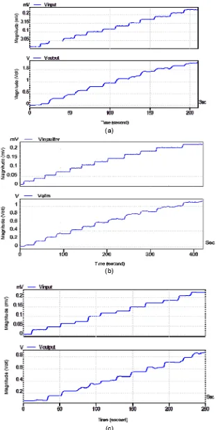
The output signal from the AD536 in the next stages will be used to feed a microcontroller. Any input signal to the must be set to a certain magnitude so that they will not damage the microcontroller. For signal conditioning between the AD536 and the microcontroller, an operational amplifier LM358 is utilised. The schematic diagram and electronic circuit of the filter, converter, and conditioner unit are illustrated in Figure 2 meanwhile a sample of the signal output is given in
Figure 3.
Figure 2. The filter, converter, and conditioner unit schematic diagram
Figure 3. A sample of signal output from rms to dc converter
3. Calibration
correlation factor between the actual electric field in vicinity received by REFM and the output of the integrated unit.
2.3. Methodology
The REFM calibration setup is shown Figure 4. The REFM is placed under the cloud simulator connected to the HVDC supply. The input voltage HVDC supply is controlled by a variable voltage regulator (VAR) at the low voltage side.
Three distances (d) settings were used in this calibration work, i.e. 30 cm, 48 cm, and 70 cm. The data collection was made online in which the increment of power frequency input voltage to the HV transformer from VAR (Vin-trans) and output of the integrated unit (Vout-int) were captured simultaneously. This process requires an analog to digital converter device. PicoScope 3206 was utilized as an interface to a PC.
PicoScope 3206 is rated at 20 V maximum input voltage. To step-down voltage from the power frequency input a differential probe (Tektronix P5200) is required.
Figure 4. The general of REFM calibration setup
2.4. Calibration Results
The online measurement results of EFM calibration work are shown in the
(a)
(b)
(c)
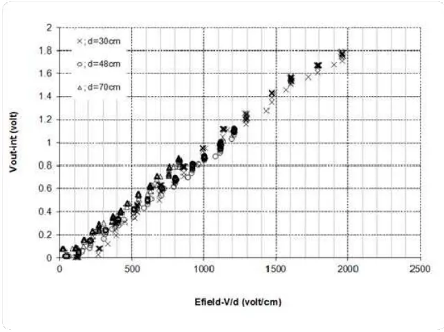
The applied electric field strength on the REFM can be presented by dividing the HVDC input voltages with the distance between cloud simulator and REFM. The detailed data presenting the correlation between electric field strength on the REFM and the output of the integrated unit is given in Figure 6. As shown, the results obtained for any particular distance are slightly scattered at the initial period where the electric field strength is under 400 V/cm.
Figure 6. Simultaneous measurement results
The obtained results are analysed by using statistical method i.e. regression and correlation analysis in order to acquire an empirical model that can be used to describe the electric field strength (E) and the Vout-int correlation. The empirical model is the function between E and Vout-int. The relationship can be written as
`(3)
There are numerous mathematical models that can be derived based on the above mathematical function. In this study, however, three mathematical models are studied to obtain the best empirical model.
Linear equation:
(4)
Exponential equation:
(5)
Power equation:
(6)
x
y
ˆ
ˆ
ˆ
(7)
where,
ŷ = dependent/response variable
ˆ
= intercept coefficient
ˆ
= independent regression coefficient x = independent/regressor variableThe intercept and slope in linear regression model can be obtained equation (8) and (9).
n
x
n
y
n i i n i i
1ˆ
1ˆ
(8)
n i n i i i n i n i i n i i i in
x
x
n
x
y
x
y
1 2 1 2 1 1 1ˆ
(9)For calculating the correlation coefficient
(
r
)
n i i n i i n i i i xyx
x
y
y
x
x
y
y
r
1 2 1 2 1)
(
)
(
)
)(
(
(10)For calculating the multiple correlation coefficient
(
R
2)
)
(
)
ˆ
(
1 2 1 2 2
n i i n i i T Ry
y
y
y
SS
SS
R
(11)where,
SS
R=
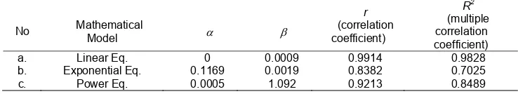
regression sum squaresTable 1 The constant calculation results and correlation coefficients of the mathematical model
No Mathematical
Model
r
(correlation coefficient)
R2
(multiple correlation coefficient)
a. Linear Eq. 0 0.0009 0.9914 0.9828
b. Exponential Eq. 0.1169 0.0019 0.8382 0.7025 c. Power Eq. 0.0005 1.092 0.9213 0.8489
Based on the above analysis it can be concluded that the linear mathematical model is the best model represent the correlation between Vout-int and E. Hence, the microcontroller is programmed as such to give a response based on the obtained linear mathematical model.
4. Wireless Data Communication System
The REFM sensor, normally, will be installed in open area distant from the data centre building. For that reason, in order to collect, record, and analyse the magnitude of atmospheric electric field from REFM sensor, a transmission system is required to send the data. The detail design regarding the wireless data communication system could be found in the previous published paper by the same author(s) [12].
The implemented method obviously shows the problems that were faced previously, i.e. manual data observation and collection – can be carried out easily and economically using the proposed approach. The routine inspection to collect data from REFM sensor, is not required anymore. Furthermore, the safety of the computing equipment can be ensured because they are no longer installed on-site.
The REFM can be installed anywhere as long as the GSM signal is available at the location. In this work the transmission time rate is one minute, which is more than sufficient to observe the fluctuation of atmospheric electric field. In addition, the REFM only uses one of the three available ports; the other two ports can be used for the other measurement purpose, if needed.
5. Conclusion
The REFM and wireless data transmission system using the REFM sensor and the GSM network is successfully developed. The wireless transmission system device is able to capture the real-time data for remote REFM sensor locations. All information about the atmospheric electric field condition sensed by the REFM sensors will be stored in a database system that could be monitored online through a website. In the future, it is envisaged that using the captured data, a mobile-phone lightning alert system using smart phones will be developed.
Acknowledgment
The authors would like to thank the Ministry of Higher Education and Universiti Teknologi Malaysia for providing a financial grant (GUP 01J95) to conduct the research. Also the Dean, Faculty of Electrical Engineering, Universiti Teknologi Malaysia is acknowledged for the permission to publish the results of the research.
References
[1] A. Fort, M. Mugnaini, V. Vignoli, S. Rocchi, F. Perini, J. Monari, et al. Design, modeling, and test of a system for atmospheric electric field measurement. Instrumentation and Measurement, IEEE Transactions on. 2011; 60: 2778-2785.
[2] MZ. Jacobson. Fundamentals of atmospheric modeling. Cambridge University Press. 2005.
[3] EJ. Tarbuck, FK. Lutgens. Earth Science 8th Edition Upper Saddle River, New Jersey 07458. ed: Pearson Education, Inc. 2006.
[4] M. Alam, H. Ahmad. Review of Lightning Warning Systems: Technical and Economical Aspects. in Proc. Int. Conf. on Electromagnetic Compatibility, Kuala Lumpur, Malaysia. 1995: 89-94.
[6] G. Diendorfer, M. Mair, W. Schulz, W. Hadrian. Lightning current measurements in Austria-experimental setup and first results: na. 2000.
[7] JC. Mosher, TM. Rynne, PS. Lewis. MUSIC for localization of thunderstorm cells. in Signals, Systems and Computers, 1993. 1993 Conference Record of The Twenty-Seventh Asilomar Conference on. 1993: 986-990.
[8] WD. Rust, RJ. Trapp. Initial balloon soundings of the electric field in winter nimbostratus clouds in the USA. Geophysical research letters. 2002; 29: 20-1-20-4.
[9] MAB. Sidik, NSCM. Shukri, H. Ahmad, Z. Buntat, N. Bashir, YZ. Arief, et al. Atmospheric Electric Field Data Logger System. Jurnal Teknologi. 2013; 64.
[10] EH. Gurban, G. Andreescu. SCADA element solutions using Ethernet and mobile phone network. in Intelligent Systems and Informatics (SISY), 2011 IEEE 9th International Symposium on. 2011: 303-308.
[11] H. Cai. A Remote Wireless Data Acquisition System Based on Ad Hoc Network and GPRS. in 2009Second International Workshop on Computer Science and Engineering, IEEE. 2009.
[12] Z. Nawawi, MA. Bakar Sidik, M. Boon Kean, H. Ahmad, Z. Buntat, N. Azlinda Ahmad, et al. Data transmission system of rotating electric field mill network using microcontroller and GSM module.