UNIVERSITI TEKNIKAL MALAYSIA MELAKA
DESIGN AND ANALYSIS OF SUSPENSION
SYSTEM FOR EXTREME BUGGY
This report submitted in accordance with requirement of the Universiti Teknikal Malaysia Melaka (UTeM) for the Bachelor Degree of Mechanical Engineering
Technology (Automotive Technology) with Honours.
by
MUHAMAD SUHAIDI BIN SAMSUDIN
B071110409
900319-08-5469
DECLARATION
I hereby, declared this report entitled “Design And Analysis Of Suspension System For Extreme Buggy” is the results of my own research except as cited in references.
Signature :
Author’s Name : MUHAMAD SUHAIDI BIN SAMSUDIN
APPROVAL
This report is submitted to the Faculty of Engineering Technology of UTeM as a partial fulfilment of the requirements for the Bachelor Degree of Mechanical Engineering Technology (Automotive Technology) with Honours. The member of the supervisory is as follow:
ABSTRAK
ABSTRACT
DEDICATION
For my beloved parents
Mr. Samsudin Bin Baharum Mrs. Fatimah Binti Mohd. Yussof
For my respected supervisor
Mr. Adnan Bin Katijan
And to all my treasured friends from
4th years BETA class
ACKNOWLEDGEMENT
First of all, I am really grateful to almighty Allah S.W.T because the strength that he give to me, I finally have finished my Bachelor Degree Project without any delay and major problem. I am also very grateful to him for granting me a wisdom and strength to face and overcome the challenges and obstacle to accomplish this project.
I also thank to my respected supervisor, Mr. Adnan Bin Katijan for his supervision and her passion to lead me through the period of my project and without him, my project will be nothing. His guidance and help though this period helped me to understand better on working this report. It has been truly memorable and educative being student under his supervision.
Gratitude is also to all my friends in 4th years BETA class for their sharing ideas and moral support that truly have helped me during this project. The experiences and knowledge I gained throughout the process of completing this project would prove invaluable to better equip me for challenges in the future.
4.7.7 Rear Lower Arm Structure Analysis 48
4.8 Kinematics & Compliance Analysis 51
4.8.1 Front Suspension K&C Analysis 52
4.8.2 Rear Suspension K&C Analysis 54
CHAPTER 5 : CONCLUSION & FUTURE WORK 56
5.1 Conclusion 56
5.2 Future Working 57
REFERENCES 58
APPENDICES
A Detail Child Part Drawing B Tire C Rim D Wheel Hub E Absorber F Ball Joint G Bushing
LIST OF TABLES
3.1 Gantt Chat 24
4.1 List Of Front Suspension Components 27
4.2 List Of Rear Suspension Components 29
4.3 List Of Standard Components 30
4.4 List Of Fabricate Components 31
4.5 Quality Of Element 33
4.6 Material Characteristics 33
4.7 Quality Of Element 36
4.8 Material Characteristics 36
4.9 Quality Of Element 39
4.10 Material Characteristics 39
4.11 Quality Of Element 42
4.12 Material Characteristics 42
4.13 Quality Of Element 45
4.14 Material Characteristics 45
4.15 Quality Of Element 48
LIST OF ABBREVIATIONS
CATIA - Computer Aided Three-dimensional Interactive
Application
BDP 1 - Bachelor Degree Project 1
BDP 2 - Bachelor Degree Project 2
UTeM - Universiti Teknikal Malaysia Melaka
4WD - 4 Wheel Drive
SLA - Short Long Arm
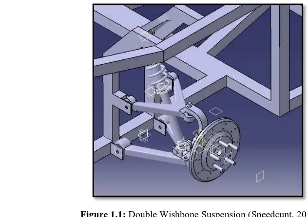
In this project, double wishbone suspension had been selected to use by extreme buggy. This due to advantages of this suspension system and it compatibility with extreme buggy chassis. This suspension usually attaches to front or rear wheel where hub assembly attach to the single point and chassis with two points. This will maintain a straight tire during driving and prevent wheel from turn to the side.
Figure 1.1: Double Wishbone Suspension (Speedcunt, 2012)
1.2 Problem Statement
Suspension system is the most important thing when designed an extreme buggy car. In recent years, handling stability and ride with a comfort is a very important features when design an off-road vehicle. In off-road terrain, the track consists of all kinds of obstacles that could easily bind up suspension of any buggy car. Thus, to make the buggy more compatible with extreme terrain, it is necessary to design a suspension system that can handle the roughest of bump without affecting vehicle stability and at the same time it provide a smooth ride to the driver and passenger. This mean a strong and tough suspension is needed to build an extreme buggy that suitable for all challenging terrain.
1.3 Objective
Based on the title “Design and Analysis of Suspension System for Extreme
Buggy”, the objectives to be achieve at the end of this project are as below :- To design and analysis suspension system for extreme buggy.
1.4 Scope & Limitation
This extreme buggy will be design with two seats for driver and passenger. It must be suitable and practical to be use on a rough and extreme terrain. This buggy will use 1.3 Litre engine from Perodua Kembara. It is 4WD with front mounted engine. This project will use CATIA V5R19 software to design suspension system and produce details child part drawing. Then, by using same software, a structure analysis will be done to analysis it strength and weakness point. After that, a kinematics and compliance analysis will be run to study the movement of each component in buggy suspension. This analysis will done using HyperWorks Motion View. A raw material that will be use is A4 paper for details child part drawing. The requirement that needed to do this project is student must be able to use CATIA V5 and HyperWorks software and know how to run analysis using both software.
To study and design a suitable suspension system for extreme buggy. To produce details child part drawing for all component in extreme buggy
suspension system.
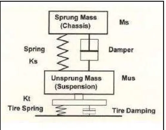
In Figure 2.1, it illustrates a line diagram model of total suspension of an automobile. The magnitude of the sprung masses and un-sprung masses are required for the analysis of suspension during the design stage. Depend on these masses, the suspension that consisting shock absorbers and spring are designed. Since the un-sprung mass will always stay as un-un-sprung mass, design should always to be keep the un-sprung mass as low as possible.
2.3 Main Types Of Suspension
There a two main types of suspension system that can be found in vehicles. It is independent and dependent suspension. It refers to ability of other wheels to move independently from of each other. While, a dependent suspension system or also call as solid axle is move dependently based on opposite wheel. This suspension system usually found on off-road vehicle and truck. This mean that dependent suspension system wheels are linked to each other. As example, when tire on the left side hit a bump, it directly affected the right side. This will cause a larger effect from original bump. Other disadvantage of dependent system is it weight commonly more compare to independent system. This cause by number of part that require in dependent system but no need in independent system.
2.4 Dependent Suspension
According to Gillespie, T. D. (1992), dependent suspension is located at end of the rigid beam so any movement from one wheel will transmitted to opposite wheel. This will cause wheel to steer and camber together. This system usually used by front suspension of heavy trucks that carry massive load. However, dependent suspension has it own advantage where wheel camber is not affect by body roll.
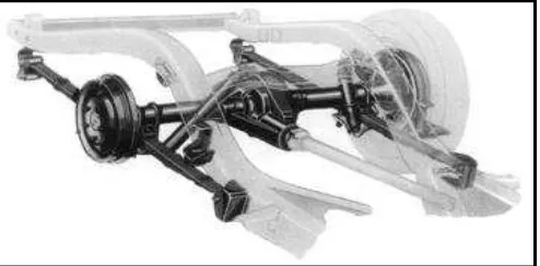
2.4.1 Hotchkiss
This suspension system is the most familiar form of the solid drive axle. The axle using semi-elliptic leaf springs as shown in Figure 2.2 and driven through longitudinal driveshaft with universal joint at transmission and axle. The spring is attach longitudinal and connect to chassis at the end while axle is attached near the midpoint. It is the simplest and least expensive of all suspensions. The Hotchkiss system use widely on the rear axle in passenger car in year 1960 and still use by mostly light and heavy truck.