UNIVERSITI TEKNIKAL MALAYSIA MELAKA
DESIGN AND ANALYSIS OF PITCHING AND ROLLING
CONTROL FOR PASSENGER CAR
This report submitted in accordance with requirement of the Universiti Teknikal Malaysia Melaka (UTeM) for the Bachelor Degree in Mechanical Engineering
Technology (Automotive Technology) with Honours
by
MUHAMMAD NAZIM BIN MOHD BASHIR
B071110344
890716-01-6145
UNIVERSITI TEKNIKAL MALAYSIA MELAKA
BORANG PENGESAHAN STATUS LAPORAN PROJEK SARJANA MUDA
TAJUK: Design and Analysis of Pitching and Rolling Control for Passenger Car
SESI PENGAJIAN: 2014/15 Semester 2
Saya MUHAMMAD NAZIM BIN MOHD BASHIR
mengaku membenarkan Laporan PSM ini disimpan di Perpustakaan Universiti Teknikal Malaysia Melaka (UTeM) dengan syarat-syarat kegunaan seperti berikut: 1. Laporan PSM adalah hak milik Universiti Teknikal Malaysia Melaka dan penulis. 2. Perpustakaan Universiti Teknikal Malaysia Melaka dibenarkan membuat salinan
untuk tujuan pengajian sahaja dengan izin penulis.
3. Perpustakaan dibenarkan membuat salinan laporan PSM ini sebagai bahan pertukaran antara institusi pengajian tinggi.
4. **Sila tandakan ( )
SULIT
TERHAD
TIDAK TERHAD
(Mengandungi maklumat yang berdarjah keselamatan atau kepentingan Malaysia sebagaimana yang termaktub dalam AKTA RAHSIA RASMI 1972)
(Mengandungi maklumat TERHAD yang telah ditentukan oleh organisasi/badan di mana penyelidikan dijalankan)
Alamat Tetap:
DECLARATION
I hereby, declared this report entitled “Design and Analysis of Pitching and Rolling Control for Passenger Car” is the results of my own research except as cited in
references.
Signature : ……….
Author’s Name : Muhammad Nazim Bin Mohd Bashir Date : 12 December 2014
APPROVAL
This report is submitted to the Faculty of Engineering Technology of UTeM as a partial fulfillment of the requirements for the degree of Bachelor of Mechanical Engineering Technology (Automotive Technology) with Honours. The member of the supervisory is as follow:
………
(ENGR.MOHAMAD HAFIZ BIN HARUN)
ABSTRAK
Laporan ini membentangkan projek dalam membangunkan pemodelan matematik untuk kajian penuh dinamik kenderaan khusus untuk brek kenderaan dan keadaan ketika mengambil selekoh. Penerbitan rumus 7 DOF model perjalanan kenderaan dibentangkan. Model perjalanan kenderaan termasuk darjah kebebasan untuk ‘pitching’, guling, dan gerakan tegak jisim ‘sprung’ dan juga gerakan tegak bagi
setiap jisim ‘unsprung’. Persamaan matematik 7 DOF kenderaan penuh adalah menjadi diterbitkan Dan simulasi dalam Matlab Simulink. Pengaturcaraan simulasi tambahan seperti CarSimEd digabungkan dan disahkan untuk perjalanan model 7 DOF untuk mengkaji dan mengawal prestasi penggantungan aktif. Prestasi perbandingan kerana rolling dan padanan kenderaan antara penggantungan pasif dengan penggantungan aktif juga akan dibincangkan.
ABSTRACT
This report presents the developing a mathematical modelling for full vehicle dynamics study specifically for the vehicle braking and cornering condition. The derivation of 7 DOF vehicle ride model are presented. Vehicle ride model includes the degree of freedom for pitch, roll, and vertical motion of the sprung mass and also vertical motion of each unsprung mass. The 7 DOF full vehicle mathematical equation are been derive and was simulate in Matlab Simulink. Additional simulation programming such as CarSimEd is combined and validated to the 7 DOF ride model to study and control the performance of active suspension. The performance comparison due to rolling and pitching of the vehicle between passive suspensions with active suspension will also be discussed
DEDICATION
I would like to thank my family for their love and support. I would especially like to thank my parents for their love, care, and financial support during my time as a student. Their help has made this achievement possible.
ACKNOWLEDGEMENT
Praise to Allah S.W.T from whom I seek help and guidance and under his benevolence we exist and without his help this project could not have been accomplished.
Firstly, I would like to take this opportunity and express my gratitude to my supervisor ENGR. Mohammad Hafiz Bin Harun for of his guidance and encouragement during this thesis period. He always appreciates whatever little progress and gives me guideline to accomplish this report. Because of him, I have achieved, and also continuously give me much inspiration by sharing his precious knowledge and experience.
Last but not least, I thank everyone who has been involved directly and indirectly in this project. The sacrifice and commitment given towards me earning my bachelor’s degree are indescribable and without them, this PSM thesis would have been impossible.
TABLE OF CONTENT
2.5 Previous studies on Mathematical modeling 11CHAPTER 3: METHODOLOGY 13
3.1 Modelling assumption 13
3.2 Project process flowchart 14
3.3 Project Gantt chart 15
3.6 Active Suspension Controller Structure 26
3.7 Modelling with Matlab Simulink 27
3.8 Validation of 7 DOF ride model using CarSimEdu 28
Chapter 5 : CONCLUSION AND RECOMMENDATION 44
LIST OF TABLES
3.1 Project Gantt Chart 15
3.2 Ziegler-Nichols tuning method 26 3.3 Parameter for 7 DOF ride model 33
4.1 PID for step steer test 39
4.2 PID for hard cornering test 41
4.3 PID for hard braking test 43
LIST OF FIGURES
2.1 Rolling motion 4
2.2 Pitching motion (dive and squat motion) 5
2.3 Passive Suspension block diagram 6
2.4 Semi Active Suspension block diagram 7
2.5 Low bandwidth or soft active suspension 8 2.6 High bandwidth or stiff active suspension 9 2.7 The result simulation in braking and cornering using passive
suspension
12
3.1 Project process flowchart 14
3.2 14 DOF Full Vehicle Model 16
3.3 A 7-DOF vehicle handling model 21
3.4 Schematic of active suspension design 25
3.5 A block diagram of PID controller 25
3.6 Control structure of active suspension system 27 3.7 Full Vehicle Model in Matlab SIMULINK 28
3.8 Vehicle body parameter 29
3.9 Suspension parameter 29
3.10 Tire parameter 30
3.11 Steering input 30
3.12 Carsim run setup 31
3.13 Graph of roll (deg) versus time(s) 31
3.14 Graph of pitch (deg) versus time(s) 32
3.15 Graph of vehicle vertical acceleration versus time(s) 32
3.16 Steering input for hard cornering 34
3.17 CarSimEd result simulation in roll angle 34 3.18 CarSimEd result simulation in pitch angle 35
3.19 Braking input for hard braking test 35
3.20 CarSimEdu pitch angle due to hard brake 36
3.21 CarSimEd vertical acceleration due to hard braking 36
4.1 Vehicle body roll in step steer test 37
4.2 Vehicle body acceleration in step steer test 38 4.3 Vehicle body pitch in step steer test 38 4.4 Active suspension vs. Passive vehicle body in roll angle 40 4.5 Active suspension vs. Passive vehicle body in pitch angle 40 4.6 Active Vs passive suspension in body roll 41 4.7 Active vs. Passive suspension in body pitch 42 4.8 Active Vs. Passive suspension in body pitch 43
LIST OF ABBREVIATIONS, SYMBOLS AND
NOMENCLATURE
Ffl - suspension force at front left corner
rl
Z , - front right unsprung masses acceleration
fl u
Z , - front left unsprung masses acceleration
rr u
Z , - rear right unsprung masses acceleration
rl u
Z , - rear left unsprung masses acceleration
CHAPTER 1
INTRODUCTION
This chapter will provide the information on behavior of vehicle when pitching and rolling. The importance of these simulating will be presented in this chapter. The problem statement, objective and scope of this project will also be included.
1.1 Background
A vehicle will act naturally in pitching and rolling during cornering and braking. Too much pitching and rolling will reduce ride comfort and also cause driver hard to manipulate and maintain the direction of movement of the vehicle.
During braking, the weight of the vehicle will be transfered from the rear tires to the front tires. This will cause the front vehicle move downward and rear vehicle to the upward. This motion is known as dive motion. When vehicle turn to the left, the weight will transfer from the left tires to the right tires. This weight transfer will occur in an opposite way, if vehicle turn to the right. This motion is known as roll motion. These motions depend on driver input on a vehicle, such as accelerating and also steering.
1.2 Problem statement
The behaviour of vehicle motion due to the hard braking, cornering and others road condition will affect the vehicle handling and stability of the vehicle. This vehicle behaviour, especially pitching and rolling during braking and cornering are being analyzed and studied. A mathematical modelling based on vehicle model is
built to represent the actual vehicle behaviour while cornering, braking and other road condition. This mathematical modelling is then used to study and control the pitching and rolling of the vehicle during braking and cornering.
1.3 Objective
1. The objective of this project is to study, analysis and control the result of the pitching and rolling control of a passenger car during braking, cornering and other road conditions.
2. The secondary objective is to validate the 7-Degree of Freedom (DOF) of full vehicle model by using Carsim software.
1.4 Project scope
The scopes of this project are:
1. Developing a 7-Degree of Freedom (DOF) full vehicle mathematical equation ride model based on vehicle model.
2. All the 7-Degree of Freedom (DOF) full vehicle mathematical equation then will be modelled in Matlab Simulink to simulate the dynamic behavior and evaluate the performance of the control structure.
3. Validate of 7-Degree of Freedom (DOF) of a vehicle model by using Carsim software.
4. The research methodology implemented in this project takes the following steps of works; literature review on the related field, study some previous works, development of equations of motion, simulation and comparison with the passive system.
1.5 Significance of the Study
The significance of this study is to gain a performance result of passive and active suspension system. Besides that, by analyzing the 7-Degree Of Freedom (DOF) full vehicle model, I am able to design the system that can improve the rolling and pitching control for the passenger car. If this system are improved, it can increase the safety and ride comfort of the passenger car when the car travelling in bumpy road, taking a cornering and braking.
1.6 Project outline
This report on “simulation study of pitching and rolling control for passenger car” is divided by 5 chapters.
Chapter 1 introduces the general background of this research, problem statement, project objective, and project scope. It also views an overall project outline.
Chapter 2 is a compilation of literature review and required information gathered from published journals, books and also from electronic media.
Chapter 3 is about the methodology used to develop 7 Degree of Freedom (7DOF) of ride vehicle model. This methodology consist of detailed equation of motion in vehicle ride model, validation steps of 7 DOF with CarSimEd and 3 types of vehicle step steer test.
Chapter 4 represents the result of simulation and also the outcome of the project. This chapter will also discuss the result obtained from the simulation of passive and active suspension.
Finally, Chapter 5 presents the conclusion and recommendation to improve this simulation to be more accurate as represent an actual vehicle model.
CHAPTER 2
LITERATURE REVIEW
This chapter provides a theory of pitching and rolling of vehicle, type of suspension, Suspension performance features, previous study on active suspension and previous study of mathematical modelling.
2.1 Theory of pitching and rolling
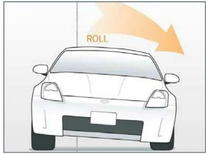
Rolling movement of the vehicle is the apparent motion of vehicle body in the longitudinal axis as shown in Figure 2.1. Rolling is achieved by a rotational velocity at the line or point of contact which is equivalent to the translational
velocity. When there is no sliding takes place the rolling motion is referred to as pure
rolling. The rolling movement usually occurs when a vehicle takes cornering and also when one of the tires hit the bump. Too much rolling movement will cause passenger discomfort and also loss of steering control.
Figure 2.1: Rolling motion (source: modified.com)
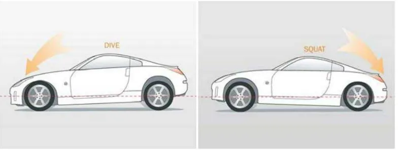
The pitching motion of the vehicle is the movement of a vehicle in lateral axis. Pitch motion in vehicle can be divided by 2 motions that is dive and squat motion. Figure 2.2 showed the dive and squat motion of the vehicle. A dive motion occurs when a driver stops or brakes their vehicle suddenly. A squat motion will take place when a driver suddenly accelerates their car. The impact of dive and squat motion will cause discomfort to passengers and also may damage vehicle body.
Figure 2.2 : Pitching motion (dive and squat motion) (Source: modified.com)
2.2 Suspension
Suspension is the main component that controls the movement of the pitching and rolling of a vehicle. Vehicle suspension system is a mechanism that physically separates the body of the vehicle with tyred wheels. Vehicle suspension system provides two functions that contribute to the vehicle control and braking for good security and driving comfort, maintaining the level of comfort when going through uneven road, the bumps and absorb vibration.
Balance suspension is very necessary to control the pitching and rolling of the vehicle. The only interactions between car and road are the four contact patches of the tires and it is very important to exploit these areas optimally, because all the road or ground forces acting on the vehicle do so through the contact patches of the tires.
The suspension also helps to protect the vehicle itself and any goods or luggage from
break and wear. Passive, semi-active and active are the three type of suspensions for the vehicle.
Therefore, generally a system of links connects the unsprung mass (wheel, brake, steering hub) to the sprung mass (car body). The geometry of these links is a trade off between optimal orientation of the wheels with respect to the road in case of suspension travel caused by bumps in the road and suspension travel caused by cornering. The springs have to be stiff enough to prevent exaggerate rolling of the car’s body; otherwise the geometry of the suspension system must be able to fully compensate for this situation. In order to avoid exaggerate rolling the system are attached with anti-roll bar. After that, the spring stiffness can be reducing in order to improve the comfort. However, the anti-roll bars stiffness function is restricted because it is it is unable to transfer the vibration from the road surface from one wheel to the other.
2.2.1 Passive suspension
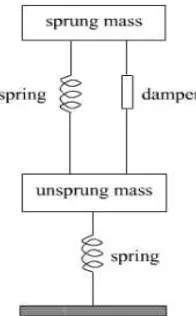
A passive suspension is a conventional suspension consists of non-controlled spring and shock-absorbing damper as shown in Figure 2.3. Passive suspension system controls the movement of vehicle body and wheel by limiting their relative velocities to a rate that give the driver comfort ability. Passive suspension means that the suspension only controls the motion of the vehicle body and wheel by limiting the suspension velocity according to the rate determined by manufacturer.
Figure 2.3 : Passive Suspension block diagram (Source: Prof Dr. Yahya, 2006)
2.2.2 Semi Active Suspension
The semi-active suspension has the same aspect as passive suspension but the damper has two or more selectable damping rate as shown in Figure2.4. In early on semi-active suspension system, the regulating of the damping force can be achieve by utilizing the controlled dampers under closed loop control, and such is only capable of dissipating energy. Two types of dampers are used in the semi-active suspension namely the two state damper and continuous variable dampers.
Figure 2.4 : Semi Active Suspension block diagram(Source: Prof Dr. Yahya, 2006)
2.2.3 Active Suspension
The active suspension is characterized by the hydraulic actuator that place in parallel with the damp and the spring. Since the hydraulic actuator connects the unsprung mass to the body, it can manipulate both the wheel hop motion as well as the body motion. An active suspension is one in which the passive component is augmented by hydraulic actuators that supply additional force.
An active suspension is different from the conventional passive suspensions in their ability to inject energy into the system, as well as store and dissipate it. An active suspension can be divided by 2 categories; low bandwidth or soft active suspension and the high bandwidth or stiff active suspension. The advantage of such
active suspension is that even if the active hydraulic actuator or the control system fails, the passive components come into action.
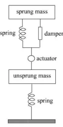
A low bandwidth or soft active suspension can be characterized by an actuator that in series with a damper and the spring as shown in Figure 2.5. A low bandwidth system aims to control the suspension over the lower frequency range, and especially around the rattle space frequency. At higher frequencies the actuator effectively locks-up and hence the wheel-hop motion is controlled passively.
With these systems we can achieve a significant reduction in body roll and pitch during manoeuvres such as cornering and braking, with lower energy consumption than a high bandwidth system. A wheel hop motion is controlled passively by the damper, so that the active function of suspension can be restricted to body motion. Therefore, such type of suspension can only improve ride comfort.
Figure 2.5 : Low bandwidth or soft active suspension (Source: Prof Dr. Yahya, 2006)
A high bandwidth or stiff active suspension is characterized by an actuator placed in parallel with the damper and the spring; generally consider an actuator connected between the sprung and unsprung masses of the vehicle as shown in