Abstract—In an Unmanned Underwater Vehicle (UUV), the craft's orientation, velocity, and gravitational forces are the important measurements to make sure the UUV’s navigation system can be fully operated. Most of the current UUV system uses pressure sensor to control the navigation of the craft. But the pressure sensor is not suitable to use in getting UUV’s navigation data or information. Without the information on UUV’s navigation, there are difficult to monitor the movement of UUV. This project introduces a methodology to analyze the position, velocity vector and the rotation of UUV, using a combination of accelerometer and gyroscope. This sensing unit is a combination of Accelerometer ADXL-345 sensor and Gyroscope ITG-3200 sensor called as an Inertial Measurement Unit (IMU). The measurement unit will be programmed by an Atmel microcontroller (Arduino UNO) to get the important data of the UUV’s navigation system. The real-time data of sensing unit communicated with Serial Chart and Processing software to get output graph and real-time 3D animation of UUV. From this project outcome, the movement of UUV is monitored in processing software. Hence, the navigation system of a UUV such as auto depth control, left-right movement and obstacle avoidance purpose can be improved.
Index Terms—unmanned underwater vehicle, navigation system, auto depth control, inertial measurement unit
I. INTRODUCTION
Within the past few decades, there has been an explosion of interest in Autonomous Underwater Vehicle (AUV) and the Remotely Operated Underwater Vehicle (ROV). AUV and ROV are being utilized to explore the ocean depth, survey and aid in salvage operations, and are even used in keeping the safety of soldiers and sailors [1-2]. The current crop of Unmanned Underwater Vehicle (UUV) is utilized in areas where the main navigational hazard is the ocean bed. The next generation of UUVs will need to be able to navigate in water with a variety of obstruction: pier pylons, kelp beds, oil platforms, etc. The usage of a UUV in typical military mission is to map an area and detect or determine if the seabed area have any mines. It also can make sure that an area (such as a harbor) that is protected monitoring by UUV for detect new unidentified objects. In the field of anti-submarine warfare, UUV also can use to aid in the detection of manned submarines [3].
Manuscript received August, 2013.
M.S.M. Aras, Faculty of Electrical Engineering (FKE), Universiti Teknikal Malaysia Melaka (UTeM), Malaysia.
S.S. Abdullah, Faculty of Electrical Engineering (FKE), Universiti Teknikal Malaysia Melaka (UTeM), Malaysia.
F.A. Azis, Faculty of Electrical Engineering (FKE), Universiti Teknikal Malaysia Melaka (UTeM), Malaysia.
The technology of UUV must be clean and not pollute the environment as found in a renewable energy system [4 – 5]. Many researchers do some studies on the navigation system on UUV can be referred to [6 – 14].
In this project, the main purpose is to analyze the navigation of UUV by using a combination of Accelerometer ADXL-345 and Gyroscope ITG-3200 sensor with low cost implementation. By using the output graph of this sensing unit, the value of angular rate, degree, and translational acceleration of a UUV can be obtained. Hence, the improvements of the navigation system of a UUV such as auto depth control left-right movement and obstacle avoidance purpose. Without the help of output graph and 3D real-time animation, there are a bit difficult to improve the movement by changing the coding of left-right movement, auto depth or obstacle avoidance programs [15]. One clear benefit in this project is the significant economic if compared this accelerometer and gyroscope sensing unit with fully GPS+IMU navigation control system.
The main scope of this project is to design an inertial sensing unit (accelerometer ADXL345 + gyroscope ITG3200) for getting the data in angular rate and acceleration and analysis the movement of UUV. The sensing system should be waterproof for safety because it plays with current and water is one of the good conductor mediums. Software design which including software programming (Arduino UNO) and Serial Chart software program should be done before real time environment testing. The Processing software is used for monitoring the UUV’s pitch and roll. The underwater vehicle will only consist of simple navigation programs and the maneuverability consisted forward and rotation movement.
II. THEORETICAL AND FORMULATION
The IMU reading that can be read in Arduino is in raw data unit, these raw data need to convert to acceleration and angular velocity for plot the output graph [16]. There are few simple equations that need to be considered in getting the Theorem Pythagoras, we can get the distance of X, Y and Z:
Analysis Movement of Unmanned Underwater
Vehicle using the Inertial Measurement Unit
Analysis Movement of Unmanned Underwater Vehicle using the Inertial Measurement Unit
(4)
(5)
(6)
From (4), (5) and (6), we can get the angles by using trigonometry formula:
(4)
(5)
(6)
From (7), (8) and (9), the angles can determine with respect to x-axis, y-axis and z-axis. These theta values are in radian unit, so now we need to convert the theta of x, y and z into a degree as shown in (10).
(10)
The IMU will not give the output degree from 0 to 360 for 1 circle. For X-axis and Y-axis, the 1st quadrant is 0 to 90 degrees, 2nd quadrant is 90 to 0 degrees, 3rd quadrant is 0 to -90 degrees and 4th quadrant is 90 to 0 degrees that show in Fig. 1.. For Z-axis, 1st quadrant is 0 to 90 degrees, 2nd quadrant is -90 to 0 degrees, 3rd quadrant is 0 to -90 degrees and 4th quadrant is 90 to 0 degrees.
Figure1: Orientation of angle output at X-axis
III. METHODOLOGY
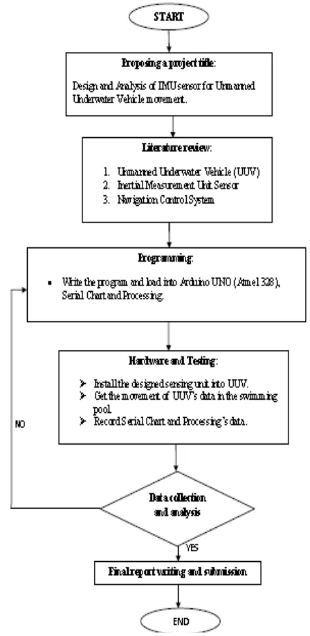
Figure 2 shows the whole system that has been constructed for the purpose of monitoring the UUV movement patterns. The system includes; tri-axial accelerometer (ADXL-345) and tri-axis gyroscope (ITG-3200), a microcontroller board (Arduino-UNO), a personal laptop, Serial Chart and
Processing software. The MEMS accelerometer ADXL-345 and gyroscope ITG-3200 is the measurement unit to sense the motion movement of UUV. As seen in the Figure 2, the output data of sensing unit will be processed with the help of written program of the microcontroller and the output of the microcontroller will translate into the laptop via USB communication. After that, Serial Chart and Processing program receives the serial port data and visually plot the output graph of the data from the sensing unit graphical form. The input voltage of the microcontroller and the sensing unit can simply provide via USB communication cable because the power supply from the USB port is sufficient. As a result, the sending unit provides continuous real time data that can be analytically the movement of UUV. Fig. 3 shows the overall process of the methodology for this project.
Figure 3: Flow chart of methodology 1st
2nd
3rd 4t
h -90 to 0
0 to 90 90 to
0
Figure 2: Illustration of the System
A. Accelerometer ADXL-345
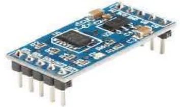
ADXL-345 as shown in Fig. 4 is a 3-axis MEMS accelerometer and produced digital output. The good resolution and provided ± 16g, ±8g, ±4g, ±2g range makes it widely used in several applications [17-18].
Figure 4: Accelerometer ADXL-345
The other main features are:
- X, Y, Z axis acceleration sensors on a single chip - Low power consumption (23microAmprere and 1.7V) - High resolution up to 13 bit with a range of ± 16g - I2C and SPI interfaces
- Free fall detection
- Two different interrupt pins
B. Gyroscope ITG3200
ITG-3200 as illustrated in Fig. 5 is a 3-axis MEMS gyroscope and produced digital output to the microcontroller. The most important is this sensor is the world first single chip with digital output and its application is a motion analysis in gaming and 3D mice [19].
The other main features are:
- X, Y, Z axis angular velocity sensors integrated on one chip - Tiny size (14mm x 19mm)
- Configurable scale range of +-2000deg/Sec - 16 bit ADC (analogue to digital converter) - Sensitivity of 14.375 LSBs per °/Sec - Configurable low pass filter [20] - I2C interface
Figure 5: Gyroscope ITG-3200
IV. RESULT AND ANALYSIS
Table 1, Table 2 and Table 3 shows the reading of accelerometer sensor at z-axis, y-axis and x-axis respectively. Meanwhile, Table 4 shows the data obtained after adjusting the coding of Arduino by referring to the offset error.
Table 1: Reading of accelerometer sensor at z-axis
Analysis Movement of Unmanned Underwater Vehicle using the Inertial Measurement Unit
Table 4: The reading after adjusting the coding of Arduino by referring to the offset error.
From the table 1, the average reading of z-axis is -10.53m/s2. By referring to acceleration of Earth Gravity, -9.81m/s2, the offset error as (11).
-9.81m/s2 – (-10.53m/s2 ) = +0.72m/s2 (11)
Percentages of offset error are as (12), (13) and (14).
X-axis, [-9.81-(-9.84)] / -9.81 * 100% = -0.31% (12)
Y-axis, [-9.81-(-9.79)] / -9.81 * 100% = +0.20% (13)
Z-axis, [-9.81-(-9.83)] / -9.81 * 100% = -0.20% (14)
Since the result shows that X, Y and Z-axis error is in the range between - 0.4% to + 0.3%, so this result is acceptable because this error is small and do not affect the actual result. There is no changing for the coding after this adjustment.
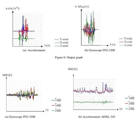
(a): Accelerometer (b) Gyroscope ITG-3200
Figure 6: Output graph
(a) Gyroscope ITG-3200 (b) Accelerometer ADXL-345
Figure 6 (a) shows the graph of this experiment part 1 result. The x-axis of the graph is time (second) and y-axis is acceleration (m/s2). The green color line is the z-axis of acceleration, the red color line is y-axis of acceleration and the blue color line is x-axis of acceleration. From the output graph, green color (z-axis) line was vibrates, following by vibration of the blue color line (y-axis) and the last vibration is the red color line (x-axis). The output graph is matched with the sensor’s box moving sequences. So, the Serial Chart software successfully communicated with the Arduino via serial communication port.
Figure 6 (b) shows the Serial Chart real-time output graph of gyroscope ITG-3200. From the Figure 6 (b), the x-axis of the graph represented the time in second and y-axis of the graph represented a degree per second of gyroscope’s x, y and z-axis. We can observe that there are 3 maximum points at the positive side and 3 minimum points at the negative side. So, this gyroscope successfully communicated between Arduino and Serial Chart software via serial communication port.
Figure 7 (a) and (b) shows the graph of the forward movement of UTeM glider using gyroscope and accelerometer respectively. The theoretical velocity of this glider is 0.13 m/s. The distance of this movement is 2 meters, and time taken is about 17 second. From these graphs, the z-axis was more stable than x-axis and y-axis. The less vibration shows that the glider does not too much changing in z-axis, which means the frequency vibration of glider at z-axis was less than the vibration at axis and x-axis. The buoyancy force is nearing equal to the glider gravity force so that the glider always stable at the surface of water.
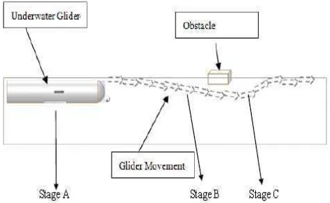
The x-axis and y-axis line are more vibrant in the output graph. As observed, the swimming pool has a water flow caused by the filtering water process and it caused the vibration at x-axis and y-axis. The glider also produced the water flow by its forward motor, this flow was mixed with the flow of filtering and produced larger unwanted flow. The forward movement of glider also caused the vibration of y-axis. This movement produced by the backward force of the motor. When the backward force, inertial force of the glider after it move forward and the resistance of the water mixed, the vibration of y-axis being stronger as shows in Figure 7 (a) and (b). It means when the initial time equal to zero, the y-axis and x-axis graph were more stable if compare after the glider move after 10 second (inertial of glider and water resistance occur). The expected movement of glider for obstacle avoidance is shown in Figure 8.
At stage A, the 3D animation output as Figure 9. The pitch angle shows in Processing are -1° and roll angle is 2°.
Figure 9: 3D output at stage A.
At stage B, the 3D output as Figure 10. The pitch angle is -43° and the roll angle is 4°.
Figure 10: 3D output at stage B.
In stage C, the 3D output as Figure 11. The pitch angle is +43° and the roll angle is -4°.
Figure 11: The 3D output at stage C.
Analysis Movement of Unmanned Underwater Vehicle using the Inertial Measurement Unit
43°. The reading for roll is 4°and this might caused by the water flow inside the swimming pool. Stage C is the stage that the wings become 43° and the glider will push by the buoyancy force to rise up.
V.CONCLUSION
A measurement unit was successfully developed and experiment using accelerometer ADXL-345 and gyroscope ITG-3200 with interfaced to Atemel 328 IC in Arduino UNO board. The data from these two sensors is successfully interpreted in a graphical form using Serial Chart software via computer serial communication port.Many technical challenges such as interacting between microcontroller and serial communication port, programming of Arduino, graph plotting, assembling sensor into UTeM glider and the waterproof of the glider and sensor were successful resolved during this project. The most time taken for this project is to interface the hardware (sensor) and the software (Arduino) thru programming. After defining the address of both sensors in microcontroller programming using I2C communication, then just the overall project can be start and analysis thru the graphical form. There are 3 critical parts that might have water leaking into the UTeM glider body. The 1st one is left-right servo motor hole, 2nd is a forward motor’s shaft of UTeM glider and the last one is the cap of the glider. This experiment tested after seal the hole on the left-right motor and glider cap. For the shaft of forward motor, only put the grease on it. All trail testing is 30 minutes to fill in 40kg iron rod to make sure the body of glider fully submerged in the lab pool water. The movement of the glider in pitch and roll angle was a successes monitor in the computer. The angle of the glider in the obstacle avoidance system and forward movement was monitored in computer software and these angles acted as the close loop feedback for each movement. In future, the signal of IMU can be applied in the open loop system such as obstacle avoidance application for reducing the steady state error caused by the movement of the glider. This project provides useful data for a future UUV project in UTeM by analysis and predicting the pace of UUV’s movement such as fully automatic obstacle avoidance system. By improving the data fusion of accelerometer and gyroscope, there was success to get the output 3D animation with the help of the Processing software
VI. ACKNOWLEDGMENT
The authors would like to thank Universiti Teknikal Malaysia Melaka (UTeM) for the financial support of this project and the permission to publish the work.
REFERENCES
[1] Paul A. Miller, Jay A. Farrell, Fellow, IEEE, Yuanyuan Zhao, and Vladimir Djapic. Autonomous Underwater Vehicle Navigation. IEEE JOURNAL OF OCEANIC ENGINEERING, VOL. 35, NO. 3, JULY 2010.
[2] M.S.M Aras, H.A. Kasdirin, M.H. Jamaluddin, M F. Basar, Design and Development of an Autonomous Underwater Vehicle (AUV-FKEUTeM), Proceedings of MUCEET2009 Malaysian Technical Universities Conference on Engineering and Technology, MUCEET2009, MS Garden, Kuantan, Pahang, Malaysia, 2009. [3] Yanrui Geng, Ricardo Martins, Joao Sousa. Study of Inertial
Measurement Unit Sensor Accuracy Analysis of DVL/IMU/Magnetometer Integrated Navigation System using Different IMUs in AUV. 8th IEEE International Conference on Control and Automation Xiamen, China,2010.
[4] M. F. Basar, A. Ahmad, N. Hasim and K. Sopian, “Introduction to the Pico Hydropower and the status of implementation in Malaysia,” IEEE Student Conference on Research and Development (SCOReD), pp. 283-288, ISBN: 978-1-4673-0099-5, Cyberjaya, Malaysia, 19-20 December 2011.
[5] M. F. Basar, A.A. Rahman, Z Mahmod, “Design and Development of Green Electricity Generation System Using Ocean Surface Wave,” PEA-AIT International Conference on Energy and Sustainable Development : Issues and Strategies (ESD 2010), pp. 1-11, ISBN: 978-1-4244-8563-5, Chiang Mai, Thailand, 02-04 June 2010. [6] D. Hazry, M. Sofian, A. Zul Azfar. Study of Inertial Measurement Unit
Sensor. Proceedings of the International Conference on Man-Machine Systems (ICoMMS), October 2009.
[7] Pan-Mook Lee, Sea-Moon Kim, Bong-Hwan Jeon, Hyun Taek Choi and Chong-Moo Lee. Improvement on an Inertial-Doppler Navigation System of Underwater Vehicles Using a Complementary Range Sonar. IEEE JOURNAL, 2007
[8] Pan-Mook Lee, Bong-Huan Jun, Kihun Kim, Jihong Lee, Taro Aoki, and Tadahiro Hyakudome. Simulation of an Inertial Acoustic Navigation System with Range Aiding for an AutonomousUnderwater Vehicle. IEEE JOURNAL OF OCEANIC ENGINEERING, VOL. 32, NO. 2, APRIL 2007.
[9] Shojiro Ishibashi, Satoshi Tsukioka, Takao Sawa, Hiroshi Yoshida, Tadahiro Hyakudome, Junichiro Tahara, Taro Aoki, Akihisa Ishikawa. The Rotation Control System to Improve the Accuracy of an Inertial Navigation System Installed in an Autonomous Underwater Vehicle. IEEE JOURNAL, Tokyo, Japan, 17-20 April 2007.
[10] M.Ijliana, Navigation System of an Autonomous Underwater Vehicle For Antarctic Exploration. IEEE JOURNAL, 1997.
[11] Vadim Bistrov. Performance Analysis of Alignment Process of MEMS IMU. Hindawi Publishing Corporation International Journal of Navigation and Observation Volume 2012.
[12] Pan-Mook Lee, Bong-Huan Jun, Ji-Hong Li. Navigation and Control System of a Deep-sea Unmanned Underwater Vehicle 'HEMIRE'. IEEE Journal, 2008.
[13] N. Hasim, M.F. Basar, M.S. Aras, “Design and Development of a Water Bath Control System: A Virtual Laboratory Environment,” 2011 IEEE Student Conference on Research and Development (SCORED), pp. 403-408, ISBN: 978-1-4673-0099-5, Cyberjaya, Malaysia, 19-20 December 2011.
[14] MSM Aras, SS Abdullah, SS Shafei, Investigation and Evaluation of Low Cost Depth Sensor System Using Pressure Sensor for Unmanned Underwater Vehicle, Majlesi Journal of Electrical Engineering, Volume 6 Issue 2, 2012.
[15] Shojiro Ishibashi, Satoshi Tsukioka, Takao Sawa, Akishisa Ishikawa and etc. The Rotation Control System to Improve the Accuracy of an Inertial Navigation System Installed in an Autonomous Underwater Vehicle. Nippon Marine Enterprises, LTD,2010.
[16] Maluf, N. and Williams, K. An Introduction to Microelectromechanical Systems Engineering. Published , 2nd ed. Boston: Artech House Publishers, 2004.
[17] MSM Aras, FA Azis, MN Othman, SS Abdullah,A Low Cost 4 DOF Remotely Operated Underwater Vehicle Integrated With IMU and Pressure Sensor, 4th International Conference on Underwater System Technology: Theory and Applications (USYS'12). Malaysia, 2012. [18] www.arduino.cc
[19] www.sparkfun.com
Mohd Shahrieel b Mohd Aras is a lecturer at Faculty of Electrical Engineering, Universiti Teknikal Malaysia Melaka (UTeM). He currently pursues his PhD in Control and Automation at Universiti Teknology Malaysia, Skudai, Johor. His currently research is focusing on control system design of underwater technology. ([email protected])
.
Fadilah Binti Abdul Azis is a lecturer of Mechatronics Department in Universiti Teknikal Malaysia Melaka (UTeM). She has a Bachelor of Mechatronics Engineering (Hons) from International Islamic University Malaysia (IIUM) and a MSc in Mechatronics Engineering from University of Siegen, Germany. Her research interest includes in the Emerging Technology focus areas such as Underwater Technology and Smart Material Structures. She is currently working on the development of underwater vehicle for underwater industry
Fara Ashikin Binti Ali is a lecturer of Faculty of Engineering Technology in Universiti Teknikal Malaysia Melaka. She has a Bachelor of Science in Physics and Master of Engineering in Electrical and Computer Engineering, both from Kanazawa University, Japan. Her research interest includes Underwater research, Physics and Sensor technology.