i
SMART HOME AUTOMATION USING VOICE RECOGNITION
MUHAMMAD AIMAN FAIZ BIN MOHD YUSOF
This Report Is Submitted In Partial Fulfillment of Requirements For The Bachelor Degree of Electronic Engineering (Industrial Electronic)
Fakulti Kejuruteraan Elektronik dan Kejuruteraan Komputer Universiti Teknikal Malaysia Melaka
v
ABSTRACT
vi
ABSTRAK
TABLE OF CONTENTS
Chapter Content Page
Title i
Report Status Verification Form ii
Supervisor Verification Form iii
Student Verification Form iv
Abstract v
Abstrak vi
List of Abbreviations vii
List of Figures viii
List of Tables x
I INTRODUCTION
1.1 Introduction of Project
1.2 Objective 1
1.3 Problem Statement 2
1.4 Scope of Project 3
II LITERATURE REVIEW
2.1 Overview
2.2 Home Automation 5
2.3 Microcontroller 7
2.3.1 Speed 8
2.3.2 Memory 8
2.3.3 Number of Input/ Output Ports 8
2.3.4 Packaging 9
2.3.5 Cost per Unit 9
2.4 Microcontroller PIC16F877A 9
2.5 Speech Characteristics 11
2.5.1 Speech Recognition Overview 12 2.6 Microsoft Speech SDK 5.1 (SAPI 5.1) 13
2.6.1 API Overview 13
2.7 Zigbee 14
III METHODOLOGY
3.1 Overview
3.2 The Gantt Chart 16
3.3 Methodology Workflow 19
IV RESULT AND DISCUSSION
4.1 Overview
4.2 Software Implementation 22
4.2.1 Visual Basic Software Algorithm 22
4.3.1 Designing the Circuit 27 4.3.2 Logic Level Shifting 32 4.3.3 XBee Pro Configuration 33 4.3.4 Light Emitting Diode Implementation 38 4.3.5 Relay Implementation 41
4.4 System Verification 45
4.5 Improving the Accuracy 54
V CONCLUSION AND RECOMMENDATION
5.1 Overview
5.2 Conclusion 60
5.3 Recommendation 61
REFERENCES 62
vii
LIST OF ABBREVIATIONS
API : Application Programming Interface
ASCII : American Standard Code for Information Interchange CPU : Central Processor Unit
CSMA-CA : Carrier Sense Multiple Access with Collision Avoidance CSR : Continuous Speech Recognition
DSP : Digital Signal Processor GPRS : General Packet Radio Service GUI : Graphical User Interface
IEEE : Institute of Electrical and Electronics Engineers IWR : Isolated Word Recognition
MCU : Micro Controller Unit PCB : Printed Circuit Board
SMA : Security, Monitoring and Automation
SMS : Short Message Services
viii
LIST OF FIGURES
NO TITLE PAGE
2.1 uControl Touch Screen Panel 6
2.2 PIC16F877A Pin Diagram 10
2.3 Waveform Signal 11
2.4 The API Flow Overview 14
3.1 Project Flowchart 20
3.2 Project Workflow 21
4.1 Modem Connected 23
4.2 Error Display as COM Port Not Selected or Not Open 23
4.3 Software Voice Monitoring System Flowchart 24
4.4 Timer1 Event Flowchart 25
4.5 Error Handler Flowchart 26
4.6 ASCII Conversion Flowchart 28
4.7 End Device Flowchart 29
4.8 End Device Schematic Diagram 30
4.9 PCB Layout 31
4.10 XBee Pro 100mW Module and PIC 16F877A chip 32
4.11 Logic Level Shifting Connection 33
4.12 COM Port Testing 35
ix
4.14 Configuration of Both Destination Addresses 37
4.15 Data Transmit and Receive Successfully 38
4.16 LED Graph Characteristic 39
4.17 Brightness Comparison over Different Resistance 41
4.18 Relay Activation Circuit 43
4.19 Living Hall Light, Master Bedroom Light and Living Hall Fan ON 49 4.20 Result for Living Hall Light, Master Bedroom Light and Living Hall Fan ON
49
4.21 Malay Word Being Pronounce to ON the Lamp 2 50
4.22 Result for Lamp 2 ON 50
4.23 Turn OFF All Appliances 51
4.24 Result for OFF All Appliances 51
4.25 Play Music in Playlist 52
4.26 Go to the Next Music Playlist 52
4.27 Back to the Previous Music Playlist 53
4.28 Stop Music in Playlist 53
4.29 Speech Recognition Option 54
4.30 Editing the Malay Word 56
4.31 Word Being Patterned In Uppercase Letter 57
4.32 Word Being Recorded 58
x
LIST OF TABLES
NO TITLE PAGE
3.1 The Gantt Chart 17
4.1 User Routine (Software Only) 46
4.2 Command List for DC Modes 47
4.3 Command List for AC Modes 48
CHAPTER 1
INTRODUCTION
1.1 Introduction of Project
1
1.2 Objective
There are several objectives involved in this project that should be focused in order to achieve the design of the project.
To design a smart home automation system using voice recognition.
The idea is to create smart home systems that use biometric method such as human voice as directive to activate electrical appliances. Hence, voice will be used as input to the system.
To provide a friendly user interface for smart home automation system
especially for disabled and elderly.
The idea is to design a simple, yet friendly Graphical User Interface (GUI) to aid users especially disabilities and elderly person to do their daily home routine. The system should be using a simple understanding language for easy guidance.
To design an embedded wireless controller system for the project
The idea is using the wireless system to control home appliances wirelessly, which provide easy installment rather than heavy reconstruction by using wired system.
Improve the percentage of recognition accuracy to activate the appliances.
2
1.3 Problem Statement
Generally conventional home using simple latching switch that being connected to the power supply for controlling electrical appliances such as lighting. This switch usually located at wall in sight of the controlled appliances.
Nowadays new technologies create new solution for home system. This improvisation called home automation. There have been several commercial and research projects on smart homes. Many of the commercial products use remote control whether it has button or fully touch screen.
Still, monitoring and controlling the appliances need some movement and physical contact. Thus, this will be a burden to disable person especially for the disabled and elderly people.
3
1.4 Scope of Project
In order to achieve the objective of the project, several scopes need to be identified. The scope of the project includes:
Meant to control and monitor house appliances using voice. For voice recognition, Microsoft Speech Recognition engine will be use.
4
1.5 Project Methodology
Phase 1: Software Development
This development is to build Graphical User Interface (GUI) for control and monitoring the system using Visual Basic.
Phase 2: Hardware testing and debugging
Testing and debugging at this moment not using permanent circuitry but only using software. Implementation of circuit will be design in Proteus software.
Phase 3: Software and Hardware Testing
This phase involving testing the program by only using circuit in Proteus and GUI design. Both will be connected using serial communication port in order to test them.
Phase 4: Hardware Implementation
At this moment, the permanent circuitry will be design. Once again, this circuit will be linked to GUI to test the functionality.
Phase 5: Analysis Data
CHAPTER II
LITERATURE REVIEW
2.1 Overview
5
2.2 Home Automation
The demography of the world population shows a trend that elderly population worldwide is increasing rapidly as a result of the increase of the average life expectancy of people [1]. Home automation is one of the fast growing industries that keep promising and satisfy the world population in such many ways. It been created due to many aspect such for those who seeking luxury modern lifestyle while others being offers to those with special needs like elderly and disable person.
“Home automation is a very promising area. Its main benefits range from
increased comfort and greater safety and security, to a more rational use of energy and other resources, allowing for significant savings. It also offers powerful means for helping and supporting the special needs of people with disabilities and, in particular, the elderly. This application domain is very important and will steadily increase in the
future [2].”
According to Khusvinder Gill, Shuang-Hua Yang, Fang Yao, and Xin Lu, in recent years the introduction of network enabled devices into the home improvement has proceed at an unprecedented rate [3].
In other word, home automation also known as domotics. Domotics is defined as
“A set of element that, when installed, interconnected and controlled automatically in a
building, save the users worrying about routine everyday actions, providing improvement
in their comfort, in energy consumption, in security and in communication as well” [4].
6
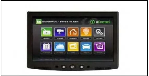
[image:21.612.182.467.309.456.2]Due to its potential, several products has been commercial and further development has been carry out to create more smart design. As in Figure 2.1, this is the an integrated platform for security, monitoring and automation (SMA) from uControl [5]. The system provide user a 7 inch touch screen panel with wireless controlling ability that connected to security alarm and other home appliances. uControl also provide user an ability to control their appliances from any browser or cell phone, alert via email or SMS, WiFi, GPRS, and cameras. With friendly GUI system, it also can manage video, photos, web content and social networking application.
Figure 2.1: uControl Touch Screen Panel (www.thetechjournal.com)
7
.2.3 Microcontroller
Microcontroller has been a major revolution in the field of electronics engineering. It has such a capability of input and output control as well as data processing incorporated into a single chip. It a best choice for application that involve embedded applications and system which require less processing capabilities, thus reducing the cost and complexity in the process of product design.
Microcontroller is defined as a “a self contained computer on a chip consisting of a central processing unit, non volatile program memory, random access memory for data
storage, with various input-output capabilities” [6].
However, it is important to choose the suitable microcontroller for the design. Basically, several features need to be considered before choosing the suitable microcontroller such as:
Speed Memory
Number of input/ output port Packaging
8
2.3.1 Speed
High speed performance is needed for time critical system such as digital signal processor (DSP) which can perform fast calculation. Also it is important for data to be process in real time function.
2.3.2 Memory
Memory use will depend on how critical the designs are, usually use for complex situation. Based on the complexity of the design, microcontroller should have suitable data space to store the program data. However, the price of microcontroller will cost higher based on memory capacity. Thus, using the suitable microcontroller is advisable.
2.3.3 Number of Input/ Output Ports
9
2.3.4 Packaging
The selection of microcontroller package is essential in product design. A suitable packaging is necessary because it could affect the physical presentation of the finished product. Usually it comes with anti static box that cover up the unit.
2.3.5 Cost per Unit
Microcontroller unit used in embedded system target simple system and application are cost sensitive, hence the price may be worth considering in developing a marketable product.
2.4 Microcontroller PIC 16F877A
As for PIC16F877A, it provides a basic feature and cheap solution, where it enough to work as receiver [8]. Figure 2.3 shows the detail of PIC16F family features:
High performance RICS CPU
Operating speed: DC-20Mhz clock input DC- 200ns instruction cycle
Up to 8K x 14 words of FLASH Program Memory, Up to 368 x 8 bytes of Data Memory (RAM), Up to 256 x 8 bytes of EEPROM Data Memory