DESIGN CONTROL AND MONITORING TECHNIQUE FOR DOMESTIC USAGE VIA PC BASED
SAIFUL AMIN B KAMARUDDIN
BARCHELOR OF ELECTRICAL ENGINEERING (INDUSTRIAL POWER)
DESIGN CONTROL AND MONITORING TECHNIQUE FOR DOMESTIC USAGE VIA PC BASED
SAIFUL AMIN B. KAMARUDDIN
A report submitted in partial fulfillment of the requirements for the degree Of Bachelor’s in Electrical Engineering (Industrial Power)
Faculty of Electrical Engineering
UNIVERSITI TEKNIKAL MALAYSIA MELAKA
2012
“I hereby declare that I have read through this report entitle “Design Control and Monitoring Technique For Domestic Usage via PC Based” and found that it has comply the partial fulfillment for awarding the degree of Bachelor of Electrical Engineering (Industrial Power)”
I declare that this report “Design Control and Monitoring Technique For Domestic Usage via PC Based” is the result of my own research except as cited in the references. The report has not been accepted for any degree and is not concurrently submitted in candidature of any other degree.
ACKNOWLEDGEMENT
First and foremost , I am truly appreciate to my supervisor, En NorHafiz Bin Salim who has given me useful advices that have helped me a lot in accomplish this project and also guiding me in writing a good technical report.
Besides, I would like to extend my gratitude‟s to express my deeply thankful to all my friends answering all my doubtful concern around the field. Never forget too, I would like to give my heartily and thousand thanks to my family members for their support in order to accomplish this project.
Lastly, I would like to express my deepest gratitude to person who involved and constantly guiding me in my every step and I have learned a lot from them by their support, constructive suggestion and also critics. Thank you for lending hands when I needed them the most.
ABSTRACT
Nowadays, application of computer in control system are increasing due to the development of the information technology. The aim of this paper is to show how the computer technology can use to control and monitor the electrical appliances such as lamp and fan. The studies on existing control and monitoring technique for domestic usage via PC based will be conduct by using visual basic and microcontroller. Switching concept is used for control method to control ON/OFF of domestic application. The visual basic is use to monitor the temperature house. There for the switch fan can controlled automatic based on the temperature that set. For transmit signal to hardware, the XBee RF module is use for this project as an connector between PC and electric appliances. This method is chosen as alternative method other than traditional method because it can solve the
ABSTRAK
Pada masa kini, penggunaan komputer digunakan dalam sistem kawalan kerana perkembangan teknologi maklumat yang semakin meningkat. Tujuan kertas kerja ini adalah untuk menunjukkan bagaimana teknologi komputer boleh digunakan untuk mengawal dan mengawal penggunaan peralatan elektrik seperti lampu dan kipas. Kajian mengenai kawalan sedia ada dan teknik pemantauan bagi penggunaan domestik melalui PC akan dikawal dengan menggunakan visual basic dan microcontroller. Konsep
pensuisan yang digunakan untuk kaedah kawalan untuk mengawal ON / OFF penggunaan domestik. Visual basic juga gunakan untuk memantau suhu rumah. Oleh itu, suis boleh dikawal automatik berdasarkan kepada suhu yang ditetapkan. XBee frekuensi radio penghantaran isyarat digunakan dalam projek ini sebagai antara muka untuk penyambung antara perisian dan perkakasan. Kaedah ini dipilih sebagai kaedah alternatif selain daripada kaedah tradisional kerana ia boleh menyelesaikan isu-isu yang biasa berlaku dalam
TABLE OF CONTENTS
CHAPTER TITLE PAGE
ACKNOWLEDGMENT i
ABSTRACT ii
TABLE OF CONTENTS iii
LIST OF FIGURES vii
LIST OF TABLES AND GRAPHS ix
LIST OF ABBREVIATIONS x
LIST OF APPENDICES xi
1 INTRODUCTION 1.1 Project background 1
1.2 Problem statement 1
1.3 Objective 2
1.4 Scope 3
2 LITERATURE REVIEW 2.1 Introduction 4
2.2 Control and monitor 4
2.3 Visual Basic 5
2.3.1 Example of Graphical User Interface (GUI) 6
2.4 Wireless Communication 6
2.4.1 XBee RF Module 7
2.4.2 Bluetooth 7
2.5 Universal Asynchronous Receiver Transmitter 8
(UART) 2.6 Control Technique 9
2.7 Main Microcontroller 11
2.8 Load 13 2.8.1 LM35 Series (Temperature Sensor) 13
2.9 Summary 14
3 METHODOLOGY
3.1 Introduction 15
3.2 Project Work Flow 15
3.3 Hardware and software design 18
3.3.1 Hardware Design 18
3.3.1.1 Switching Circuit 18 3.3.1.2 Build circuit on PCB board 22 3.3.1.3 Integrated SK40C with XBee radio 26
frequency(RF) module
3.3.1.4 Integrated All Circuit 28 3.3.1.5 Hardware Development Design 29 3.3.1.6 Microcontroller Circuit Construction 30
3.3.2 Software Design 32
3.4 Design and Develop graphical user interface (GUI) 34
3.5 Summary 39
4 RESULT
4.1 Introduction 40
4.2 Result 40 4.2.1 Experiment 1- Simulation testing with Proteus 40 4.2.2 Experiment 2-Switching circuit testing use 44
relay 12V
4.2.3 Experiment 3-Integration Between XBee RF 45 module with microcontroller through GUI
5 ANALYSIS AND DISCUSSION
5.1 Analysis and discussion 50
6 CONCLUSION AND RECOMMENDATION
6.1 Conclusion 52
6.2Recommendation 53
6.2.1 XBee-Pro module 53
REFERENCES 54
APPENDICES 55
[image:11.595.101.512.169.763.2]
LIST OF FIGURES
FIGURE TITLE PAGE
2.1 User interface running on PC 6
2.2 The system diagram of XBee RF transmitter and receiver 7
2.3 Different functional blocks in the Bluetooth system 8
2.4 UART Frame Format 9
3.1 Project flowchart 17
3.2 Switching circuit 18
3.3 Switching circuit create in Proteus 19
3.4 Switching circuit constructed in Proteus 19
3.5 GUI system run with Proteus 20
3.6 Switching constructed in breadboard 20
3.7 Switching circuit testing for LED 21
3.8 Switching circuit testing for cooler fan 21
3.9 Switching circuit testing for LED and cooler fan 22
3.10 Process block for PCB board 22
3.11 Circuit design use ARES 7 Professional 23
3.12 Circuit design in 3D visual 23
3.13 Develop circuit with developer liquid 24
3.14 Etching Process 24
3.15 Drilling Process 25
3.16 PCB board after drill 25
3.17 Circuit testing 26
3.18 Integrate the XBee module with SK40C 27
3.19 X-CTU software 27
3.20 XBee integrate with PC 28
3.21 The combination of related circuits 28
3.22 Hardware is designed and installed by a few materials needs 29
3.24 PIC16F877A 30
3.25 SK40C 30
3.26 XBee radio frequency (RF) module 31
3.27 Mikro C software 33
3.28 Coding mikro C flowchart 34
3.29 GUI programming flowchart 35
3.30 Visual basic new project 36
3.31 Toolbox and windows properties of visual basic 37
3.32 Visual basic coding 37
3.33 First GUI layout design 38
3.34 Second GUI layout design 38
4.1 MikroC coding 41
4.2 Visual basic coding 42
4.3 GUI system 42
4.4 Circuit in Proteus 43
4.5 Switching circuit 44
4.6 Switching circuit integrate with XBee RF 45
4.7 Graph for accuracy of signal strength indoor testing 46
4.8 Graph for accuracy of signal strength outdoor testing 48
5.1 Graph for accuracy of signal strength at outdoor testing 51
LIST OF TABLES AND GRAPHS
TABLES TITLE PAGE 4.1 Simulation testing data 43 4.2 Address and functionality for hardware 45 4.3 Data collected for analyze the effect of wirelessly 46 technique system indoor testing
4.4 Data collected for analyze the effect of wirelessly 47 technique system outdoor testing
4.5 Fan control and monitoring based on temperature 49
LIST OF ABBREVIATIONS
VB Visual Basic
GUI Graphical User Interface IDE Integrated Development RAD Rapid Integrated Development DAO Data Access Objects
RDO Remote Data Objects ADO ActiveX Data Objects VBA Visual Basic Application
PC Personal Computer
RF Radio Frequency
GSM Global System for Mobile Communications PIC Peripheral Interface Controller
ECG Electrocardiogram
BASIC Beginner's All-purpose Symbolic Instruction Code CDMA Code Division Multiple Access
USART Universal synchronous/asynchronous receiver/transmitter PLC Programmable logic controller
PDA Personal digital assistance
IO Input output
MCU Microcontroller unit
WDT Watchdog Timer
ICD In-Circuit Debug
PIC Peripheral Interface Controller ECG Electrocardiogram
LIST OF APPENDICES
APPENDIX TITLE PAGE A Project Gantt Chart 55
B Wireless link performance 56
CHAPTER 1
INTRODUCTION
1.1 Project Background
This project design control and monitoring technique for domestic usage via PC based basically use for solve the some problem in the domestic usage. Interface between hardware and computer is call the external controller. Interface between hardware and computer is chosen that call external controller or graphical user interface (GUI). Graphical user interface (GUI) is created and developed by using Visual Basic 2008 as internal controller and monitoring system and the signal from machine language as computer is transmitted to the interface and received data from microcontroller. Besides that, XBee RF module is used as a connector between computer and electrical appliances. The module can communicate with any logic and voltage compatible universal synchronous/asynchronous receiver/transmitter (USART) through this serial port. The wireless communication is applied for transmit signal to hardware in real-time operation.
1.2 Problem Statement
Today, anything want to have a new technology. That why in order to control and monitor technique the graphical user interface (GUI) layout developed in Visual Basic (VB) is represented. This method is a alternative method compare the traditional method. This method is chosen for this project because it can solve the common some issues occur.
monthly usage can be minimized. The wireless communication is use to solve the problem for wire communication. The wire communication can increase the cost of maintenance but when use wireless communication the problem can solve.
This project also to reduce space of PLC that use for control. So for this project PIC microcontroller is choose to replace PLC.. The size and cost of interface also can reduce because PLC expensive and size is large compare PIC microcontroller interface.
Based on this project, the temperature can control loads such as fan automatic based on the temperature that set. When the loads can control automatic, the cost of TNB tariff bill can minimize.
1.3 Objective
Generally, this purpose is to control and monitoring domestic usage by using PC based. The domestic usage are represented by prototype of the domestic usage. The specific objective of this project are:
i. To study about Visual Basic and GUI system.
ii. To design a GUI for controlling and monitoring by using Visual Basic and PIC. iii. To verify and analyze GUI on control and monitoring technique for the domestic
1.4 Scope
CHAPTER 2
LITERATURE REVIEW
2.1 Introduction
When to start this project some research must have to do in order to make this project successful. For this chapter, sources such as books, articles, journals and internet as use for get some information for do this project. This research are very useful as a guide in doing this project. In this chapter, The anything research that have related with this project must be record and discussed. In order to project successful, understanding of the concept about the design control and monitoring technique for domestic usage via PC based are very important.
2.2 Control and Monitor
The main program basically control and monitor by used computer. A computer act as a brain of the system and a main controller designed to sequentially and automatically carry out a sequence of arithmetic or logical operations. For control and monitor electrical appliances, a computer must link with some interface such as wireless to operate system. To run the interface, GUI such as Visual Basic use as program. The wireless is use for alternative solution for control electric appliances in domestic usage.
For control and monitoring system, divide system to three parts:- i. Visual Basic (GUI)
ii. Peripheral Interface Controller (PIC) iii. XBee RF module
2.3 Visual Basic
The programming that use for this project is Visual Basic 2008 Express Edition. For information, the third-generation event-driven programming language like visual basic language and integrated development (IDE) are develop by Microsoft. The easy programming language such as visual basic is suitable. That is because visual basic is a graphical development features and Beginner's All-purpose Symbolic Instruction Code (BASIC) heritage.
Many functions and application can developed use Visual Basic 2008. The application such as the rapid application development (RAD) of graphical user interface (GUI) applications, access to databases using Data Access Objects (DAO), Remote Data Objects (RDO), or ActiveX Data Objects (ADO) and creation of ActiveX controls and objects are familiar with visual basic (VB) software. The databases is use for control and monitoring systems. VB is connect the interface can use parallel port or USB hub.
Visual basic software has been chosen as the control and monitor system between hardware like electrical appliances and computer. Visual basic (VB) provides not only neat interface but also a simple programming to communicate with the rest of the component block [1].
2.3.1 Example of Graphical User Interface (GUI)
The graphical user interface is very useful for this project as a system for control and monitor system. GUI can developed by use computer for transfusion data, monitors and interconnection mechanisms. A Graphical User Interface (GUI) is developed in Visual Basic , which analyses the infusion history of the system [2]. Figure 2.1 show the Graphical user interface layout.
Figure 2.1: User interface running on PC [3]
The graphical user interface (GUI) is developed in Visual Basic 2008 use to control and monitor that easy to handle. GUI use to send the data to microcontroller and display data that receiver from microcontroller.
2.4 Wireless Communication
Basically have two type of wireless communication that research in this project i. Xbee RF module
2.4.1 XBee RF Module
XBee radio frequency (RF) module is a wireless device acts as interface between host devices integrated with microcontroller and range of the radio frequency or rate of oscillation within the range is depend on the properties of the XBee module. The range of XBee RF module is depend on the frequency of alternating current electrical signal that used for transfer data to another device. This system is use alternating current electric signals for produce and detect radio waves. The range of the frequency must low than the vibration rate that most mechanical systems can respond to radio frequency. When higher than vibration rate usually the frequency refer to oscillation in electrical circuits or electromagnetic radiation.
The system includes a computer as the main controller, radio frequency transmitter and receiver in order to send the signal from user to a electrical appliances [1]. XBee RF module act as an identification method. XBee use the radio waves, relying on storing and remotely retrieving data form the sensor. Figure 2.2 show the system diagram of XBee RF transmitter and receiver. The XBee transmit ting information to remote station within range of 100 meters. However the range can be increase as per equipment of a real time system and the cost of system[4]
Figure 2.2: The system diagram of XBee RF transmitter and receiver [6]
2.4.2 Bluetooth
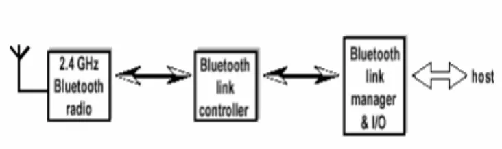
Bluetooth is a technology standard for exchanging data over short distances using short wavelength radio transmissions from mobile devices. The Bluetooth standard defines 79 channel with the frequency width of 1MHz in the ISM band [7]. Basic Bluetooth system
i. Radio transmitter (2.4 GHz Bluetooth radio) ii. Link controller-controls the transmitter.
iii. Link manager and I/O - takes care of the communication among I/O circuit and provides terminal interface for users concerning Bluetooth operated data transmission.
[image:23.595.122.488.363.472.2]The Bluetooth modules can be either built into electronic devices or used as an adaptor. In order to transmit data, it can create in computer as a computer card or externally attached via the USB port.
Figure 2.3: Different functional blocks in the Bluetooth system
2.5 Universal Asynchronous Receiver Transmitter (UART)
Universal Asynchronous Receiver Transmitter (UART) are serial chips on your computer motherboard. Function of UART is to link hardware with computer. On older computer, the chips were on the disk IO controller card. However older computer still have a serial boards.
parallel bytes, so the bit stream of UART‟s that enters the serial port via the external cable must converted to parallel bytes.
Figure 2.4: UART Frame Format [8]
The UART does some other things as a byproduct (side effect) of its primary task when it converting between serial and parallel. The voltage must be used to represent bits to converted data. When the computer parallel bus inside is high, the flow rate out the UART on the serial port side of it is much lower.
2.6 Control Technique
Today, various advantages such as ease of convenient management and low cost installation cause network technologies have been spreading widely in control engineering and applications of control system. Visual basic software, fuzzy logic and the other software are used for controllers in order to monitor and control the system.
Programming for domestic usage can create by use the fuzzy logic controller that use the JAVA language. Control of the process of the system can used fuzzy controller. When use the fuzzy, a wizard guides in the fuzzy controller is used for setup the controller. Fuzzy Toolbox is an easy-to-use visual tool for designing and implementing fuzzy logic controllers.