i
i NETWORK WIRELESS SMOKE DETECTOR
BY USING RF
LOKMAN HAKIM BIN AMRAN
This Report Is Submitted in Partial Fulfillment of the Requirements for the award of Bachelor of Electronic Engineering (Telecommunication Electronic) With Honours
Faculty of Electronic Engineering and Computer Engineering Universiti Teknikal Malaysia Melaka
ii
ii
UNIVERSTI TEKNIKAL MALAYSIA MELAKA
FAKULTI KEJURUTERAAN ELEKTRONIK DAN KEJURUTERAAN KOMPUTER
BORANG PENGESAHAN STATUS LAPORAN
PROJEK SARJANA MUDA II
Tajuk Projek : NETWORK WIRELESS SMOKE DETECTOR
BY USING RF
Sesi
Pengajian : 2009/10
Saya ………....LOKMAN HAKIM BIN AMRAN ………..……..
(HURUF BESAR)
mengaku membenarkan Laporan Projek Sarjana Muda ini disimpan di Perpustakaan dengan syarat-syarat kegunaan seperti berikut:
1. Laporan adalah hakmilik Universiti Teknikal Malaysia Melaka.
2. Perpustakaan dibenarkan membuat salinan untuk tujuan pengajian sahaja.
3. Perpustakaan dibenarkan membuat salinan laporan ini sebagai bahan pertukaran antara institusi pengajian tinggi.
4. Sila tandakan ( √ ) :
SULIT*
(Mengandungi maklumat yang berdarjah keselamatan atau kepentingan Malaysia seperti yang termaktub di dalam AKTA RAHSIA RASMI 1972)
TERHAD* (Mengandungi maklumat terhad yang telah ditentukan oleh
organisasi/badan di mana penyelidikan dijalankan)
TIDAK TERHAD
Disahkan oleh:
__________________________ ___________________________________
(TANDATANGAN PENULIS) (COP DAN TANDATANGAN PENYELIA)
Alamat :NO 101, JLN
BELANTARA 3, TMN SALENG BARU, 81400 SENAI, JOHOR
iii
iii
“I declared that this thesis is the result of my own work except the ideas and summaries
which I have clarified their sources.”
Signature : ………
Writer : LOKMAN HAKIM BIN AMRAN
iv
iv
“I hereby declare that I have read this report and in my opinion this report is sufficient in
terms of the scope and quality for the award of Bachelor of Electronic Engineering
(Telecommunication Electronic) With Honours”
Signature : ………
Supervisor’s Name : EN MOHD RIDUAN BIN AHMAD
v
v DEDICATION
Specially dedicated to my father, mother, brother and my friends for their loving,
vi
vi ACKNOWLEDGEMENT
Firstly, I would like to thank Allah because with His blessing I am able to prepare this report and final project (PSM) for Universiti Teknikal Malaysia Melaka.
Thousands of thank to my supervisor En. Mohd. Riduan B. Ahmad for his support, guidance and advice during the completion of this final project.
Special thank to my friends Mr. Sufian, Mr. hafiz and all my classmate for giving me support and encourage me to finish this report.
This project would not have been like this if they had not given great support and encouragement on me when other academic assignments and test has pressured me. The golden glory for me was during accomplishing this project is when my project successfully completed in the right path.
vii
vii ABSTRACT
viii
viii ABSTRAK
Laporan ini mengandungi maklumat tentang Rangkaian Pengesan Asap tanpa menggunakan wayar. Sistem pengesan asap ini beroperasi tanpa menggunakan wayar; dimana litar pengesan asap dan unit kawalan dihubungkan tanpa menggunakan wayar.
Didalam projek ini, jenis pengesan asap yang digunakan ialah dari jenis “Ionization”.
ix
ix TABLE OF CONTENTS
CHAPTER PAGE
TITLE i
DECLARATION iii
DEDICATION v
ACKNOWLEDGEMENT vi
ABSTRACT vii
ABSTRAK viii
TABLE OF CONTENTS ix
LIST OF TABLES xii
LIST OF FIGURES xiii
LIST OF SYMBOLS xv
I INTRODUCTION 1
1.1 INTRODUCTION OF PROJECT 1
1.2 PROJECT OBJECTIVE 2
1.3 PROBLEMS STATEMENT 3
1.4 SCOPES OF WORKS 3
1.5 PROJECT’S METHODOLOGY 3
x
x
II LITERATURE REVIEW 5
2.1 SMOKE DETECTOR 5
2.2 MICROCONTROLLER 7
2.2.1 MICROCONTROLLER PIC 8
2.2.1.1 PIC16F84A 8
2.2.1.2 PIC16F87XA 10
2.3 RADIO FREQUENCY SIGNAL 12
2.4 REMOTE CONTROL DECODER 13
2.5 PROJECT CIRCUIT 15 2.5.1 Power supply for the circuit 17 2.5.2 Push button as input for PIC microcontroller 18 2.5.3 LED as output for PIC microcontroller 19 2.5.4 Buzzer as output of PIC microcontroller 19 2.5.5 ICSP for programming PIC microcontroller 20
2.6 RF-TX-315 AND RF-RX-315 20
2.7 IONIZATION SMOKE DETECTOR IC 22
2.8 WIRELESS CAR ALARM 24
2.8.1 Temperature control system 26
III METHODOLOGY 27
3.1 DESIGNING PROCESS 27
3.1.1 Find the source about project 28 3.1.2 Construct the project circuit 28 3.1.3 Buy the components 29 3.1.4 Test the circuit on breadboard 29
xi
xi
3.1.7 Control program 30
3.1.7.1 Program PIC16F876A 31 3.1.8 Construct circuit on PCB 33 3.1.9 Flow chart for PIC programmer 35
3.2 BLOCK FIGURE 36
3.2.1 Microcontroller 37
3.2.2 Smoke detector circuit 37
3.2.3 Transmitter circuit 38
3.2.4 Receiver circuit 39
3.2.5 Buzzer 39
3.2.6 LED 40
3.3 SCHEDULE 41
IV RESULT AND DISCUSSION 42
4.1 INTRODUCTION 42
4.1.1 Power source 42
4.1.2 Output at PIC16F876A 43 4.2 PROJECT RESULT-WIRELESS SYSTEM 44
4.3 DECODER AND ENCODER 45
xii
xii
V CONCLUSIONS 48
5.1 CONCLUSION 48
5.2 SUGGESTION 49
REFFERENCES 50
APPENDICES
xiii
xiii LIST OF TABLE
TABLE TITLE PAGE
2.3 FREQUENCY 13
xiv
xiv LIST OF FIGURE
FIGURE TITLE PAGE
2.1 PIC16F84A . 9
2.2 PIC16F87XA 12
2.3 PT2272 14
2.4 TYPICAL APPLICATION AS IONIZATION 15
2.5 MAIN PIC CIRCUIT 16
2.6 PT2272 AND RF RECEIVER 16
2.7 CIRCUIT OF POWER SUPPLY 17
2.8 BUTTON CIRCUIT 18
2.9 LED 19
3.0 BUZZER 19
3.1 ICSP 20
3.2 RF-RX-315 21
3.3 MC145018 22
3.4 PIN ASSIGNMENT 23
3.5 TRANSMITTER CIRCUIT 25
3.6 RECEIVER CIRCUIT 25
3.7 TEMPERATURE CONTROL SYSTEM 26
3.8 FLOW CHART PROGRAM 30
3.9 CONTROLLER PROGRAMMER FOR DEFINE 31
4.0 STARTING SYSTEM CONDITION 31
4.1 OUTPUT OPERATION SYSTEM 32
4.2 CONTROL UNIT CIRCUIT ON BREADBOARD 33
4.3 SMOKE DETECTOR CIRCUIT 34
4.4 FLOW CHART PROGRAM 35
xv
xv
4.6 PIC16F876A 37
4.7 IONIZATION SMOKE DETECTOR 38
4.8 TRANSMITTER RX-315 38
4.9 RECEIVER RX-315 39
5.0 BUZZER 40
5.1 LED 40
5.2 WIRELESS SMOKE DETECTOR 44
5.3 CONTROL UNIT 45
5.4 ENCODER CIRCUIT 46
5.5 DECODER WITH PT2272 46
xvi
xvi LIST OF SYMBOL / ACRONYM
CCS CUSTOM COMPUTER SERVICES
dB DECIBEL UNIT
DSP DIGITAL SIGNAL PROCESSING LED LIGHT EMITTING DIODE
I/O INPUT AND OUTPUT
PCB PRINTED CIRCUIT BOARD RAM RANDOM ACCESS MEMORY
PIC PERIPHERAL INTERFACE CONTROLLER
ROM READ ONLY MEMORY
1
1 CHAPTER 1
INTRODUCTION
1.1 Background
This system has been creating to make sure that our life and properties are
2
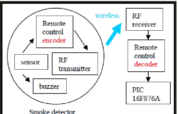
[image:18.612.184.474.69.255.2]2 Figure 1.0: System overview
1.2 Objective
The objective of this project is to design, implement, construct and prototype the network wireless
1.3 Problem Statement
Problem Statement:
1. Installing smoke detector system using cable is difficult and expensive.
2. Smoke detector and the buzzer are combining in one circuit and don’t have the control unit.
3
3 1.4 Scope
1. Use PIC16F876A.
256 bytes of EEPROM data memory.
It is a Universal Asynchronous Receiver Transmitter. 2. Use two smoke detector (Ionization type)
3. This smoke detector is using 9V battery to operate.
4. This project is using an IC remote control (PT2272) to encode data.
1.5 Methodology
Project Planning
Identify project and discussion with supervisor
Prepare Gantt Chart for guidelines and progress of project
Literature Review
Background reading and reference Search for suitable and practical circuits
Building the Hardware
Components and parts identification Data gathering and analysis.
Assembly the component on the board and test run the operation. If any problems occur after testing the circuit, the process of troubleshooting must be held.
Finishing
Testing of prototype in operation, application and result Presentation on outcome of project
4
4 1.6 Report Structure
Chapter 1 briefly explains the introduction of the Network wireless smoke detector using RF. It consist objectives of the project, research or background study of network wireless smoke detector using RF that had been done before, problems statement of the project, the scope and the methodology of the project.
Chapter 2 will be discussed about general knowledge on literature review of network wireless smoke detector using RF. It will be explained on the method and approach that had been used in previous research and also explained on the relationship of the research information and the theory.
Chapter 3 will be discuss on methodology in more detail by using the data collection method, data process method, analyze the data, and flow chart. All this will describe the process in detail of each part starting from the scratch until complete.
5
5 CHAPTER 2
LITERATURE REVIEW
2.1 Smoke Detector
In home security, there are several type of detector which like flood detector, smoke detector and temperature detector. This project is focus to create a network wireless smoke detector by using RF signal.
There are two type of Smoke Detector which are ionization type and photoelectric type.
Ionization Detectors
6
6 attracted to the positive plate, generating a small, continuous electric current. When smoke enters the ionization chamber, the smoke particles attach to the ions and neutralize them, so they do not reach the plate. The drop in current between the plates triggers the alarm.
Photoelectric Detectors
In one type of photoelectric device, smoke can block a light beam. In this case, the reduction in light reaching a photocell sets off the alarm. In the most common type of photoelectric unit, however, light is scattered by smoke particles onto a photocell, initiating an alarm. In this type of detector there is a T-shaped chamber with a light-emitting diode (LED) that shoots a beam of light across the horizontal bar of the T. A photocell, positioned at the bottom of the vertical base of the T, generates a current when it is exposed to light. Under smoke-free conditions, the light beam crosses the top of the T in an uninterrupted straight line, not striking the photocell positioned at a right angle below the beam. When smoke is present, the light is scattered by smoke particles, and some of the light is directed down the vertical part of the T to strike the photocell. When sufficient light hits the cell, the current triggers the alarm.
Which type is better?
7
7 the detector becomes ineffective. Back-up batteries may be used for photoelectric detectors.
So in this case, I have choose Ionization type because it more suitable for my project.
2.2 Microcontroller
A microcontroller (also MCU or µC) is a functional computer system-on-a-chip. It contains a processor core, memory, and programmable input/output peripherals. Microcontrollers include an integrated CPU, memory (a small amount of RAM, program memory, or both) and peripherals capable of input and output.
It emphasizes high integration, in contrast to a microprocessor which only contains a CPU (the kind used in a PC). In addition to the usual arithmetic and logic elements of a general purpose microprocessor, the microcontroller integrates additional elements such as read-write memory for data storage, read-only memory for program storage, Flash memory for permanent data storage, peripherals, and input/output interfaces. At clock speeds of as little as 32 KHz, microcontrollers often operate at very low speed compared to microprocessors, but this is adequate for typical applications. They consume relatively little power (milliwatts or even microwatts), and will generally have the ability to retain functionality while waiting for an event such as a button press or interrupt. Power consumption while sleeping (CPU clock and peripherals disabled) may be just nanowatts, making them ideal for low power and long lasting battery applications.
8
8 2.2.1 Microcontroller PIC
The full name of PIC is Peripheral Interface Controller. There are many type of PIC that we can find in market like example PIC16FXXX, PIC16C5XX and PIC17CXXXX. In my project, I have chosen to use PIC that have been produced by Microchip Technology. Below are several type of PIC that company have been procedure:
2.2.1.1 PIC16F84A
PIC16F84A which have been shown in figure 2.1 have 18-pin. Below is the features of the PIC16F84A.
High Performance RISC CPU Features:
Only 35 single word instructions to learn
• All instructions single-cycle except for program branches which are two-cycle
• Operating speed: DC - 20 MHz clock input DC - 200 ns instruction cycle
• 1024 words of program memory • 68 bytes of Data RAM
• 64 bytes of Data EEPROM • 14-bit wide instruction words
• 8-bit wide data bytes
• 15 Special Function Hardware registers
• Eight-level deep hardware stack
• Direct, indirect and relative addressing modes
• Four interrupt sources:
- External RB0/INT pin - TMR0 timer overflow