GSM MOBILE CAR ALARM SYSTEM
NURHAZWANI BT SALEH
This report is submitted in partial fulfillment of requirements for the award of Bachelor of Electronic Engineering (Industrial Electronic) With
Honours
Faculty of Electronic Engineering and Computer Engineering Universiti Teknikal Malaysia Melaka
UNIVERSTI TEKNIKAL MALAYSIA MELAKA
FAKULTI KEJURUTERAAN ELEKTRONIK DAN KEJURUTERAAN KOMPUTER
BORANG PENGESAHAN STATUS LAPORAN
PROJEK SARJANA MUDA II
Tajuk Projek : GSM MOBILE CAR ALARM SYSTEM Sesi
Pengajian : SESI 2008/2009
Saya NURHAZWANI BT SALEH mengaku membenarkan Laporan Projek Sarjana Muda ini disimpan di Perpustakaan dengan syarat-syarat kegunaan seperti berikut:
1. Laporan adalah hakmilik Universiti Teknikal Malaysia Melaka.
2. Perpustakaan dibenarkan membuat salinan untuk tujuan pengajian sahaja.
3. Perpustakaan dibenarkan membuat salinan laporan ini sebagai bahan pertukaran antara institusi pengajian tinggi.
4. Sila tandakan ( √ ) :
SULIT* (Mengandungi maklumat yang berdarjah keselamatan
atau kepentingan Malaysia seperti yang termaktub di dalam AKTA RAHSIA RASMI 1972)
TERHAD* (Mengandungi maklumat terhad yang telah ditentukan
oleh organisasi/badan di mana penyelidikan dijalankan)
TIDAK TERHAD
Disahkan oleh:
__________________________ ___________________________________ (TANDATANGAN PENULIS) (COP DAN TANDATANGAN
PENYELIA)
Alamat Tetap:.
No.114, JLN TSR 30, TAMAN SRI REMBAU, 71300 REMBAU. NEGERI SEMBILAN.
Tarikh: 30TH APRIL 2009 Tarikh: 30TH
“I hereby declare that this report is the result of my own work except for quotes as cited in the references.”
Signature : …... Author : NURHAZWANI BT SALEH
Date : 30th APRIL 2009
“I hereby declare that I have read this report and in my opinion this report is sufficient in terms of the scope and quality for the award of Bachelor of Electronic
Engineering (Industrial Electronics) with Honours.”
Signature :
Supervisor‟s Name : MISS SYAFEEZA BT AHMAD RADZI
Date : 30TH APRIL 2009
Specially dedicated to my beloved parents;
Saleh Bin Bahari and Norhayati Bt Hassan
who have encouraged, guided and inspired me throughout my journey of education.
My siblings;
Mohd Sa’izan Bin Saleh
Mohd Zamri Bin Saleh
Nurhamizah Binti Saleh
Muhamad Hafiz Bin Saleh
Hoping that you will be successful in whatever field you are involved and be strong in
facing the challenges of life.
ACKNOWLEDGEMENT
Alhamdulillah, thank Allah S.W.T for the guidance and knowledge bestowed upon me, for without it I would not have been able to come this far. I would like to express my greatest gratitude and sincere thanks to my supervisor, Miss Syafeeza Bt Ahmad Radzi, for her valuable advice and assistance in the supervision and consultation of this Final Year Project. At times, the guidance and moral support given by Miss Syefeeza very much motivating at the same time persuade me when obstacle arise throughout the interlude of completing this project.
Furthermore, I would akin to take this prospect to show a gigantic appreciation to Mr. Sivakumar Subramaniam, Industrial Electronic Tutor resting on his opinion and hold up given to me all the way through the accomplishment of this project. At the same time, I would like to exemplify an extraordinary appreciation to the Faculty of Electronic Engineering and Computer Engineering (FKEKK) on putting into practice the Final Year Project as a compulsory chore for the final year students prior to complete their course. Not forgetting Universiti Teknikal Malaysia Melaka for their contribution on the facilities and also equipments as well as creating a platform to the final year student to achieve and carry out their projects in durable manner.
Last but not least, I would like to thank my beloved family for their encouragement and never ending support. Their support and exquisite companionship is another important source of my strength. Without their devoted love and sacrifices, none of this would have been possible. My deepest appreciation goes to all my fellow friends for the companionship, fruitful suggestion, proof reading and wishes.
ABSTRACT
Vehicle security system has always been a matter of concern among vehicle owners and has become a booming industry by itself. Advancement in technology enables new and more innovative methods of vehicle safety to be introducing into the market. Today‟s vehicle security systems mostly only have to lock or unlock the door and sounding the siren in the case of intrusion. The siren can only alert those who are near the vehicle during an emergency and this shows that the existing security systems sometimes are not effective. The main objective of this project is to improve the existing system by developing a sophisticated car alarm system based on Programmable Logic Controller (PLC). This system is able to control the vehicle‟s safety through a mobile phone by giving a feedback to the vehicle owner immediately if intrusion has occurred and the owner will be able to control the vehicle‟s component by using the telephone. This project will be expected to enhance the capability of the existing system and wishes to reduce the statistic of stolen vehicles, which are on the increase day after day.
ABSTRAK
Sistem keselamatan kenderaan merupakan antara perkara yang menjadi perhatian di kalangan pemilik kenderaan dan merupakan satu industri yang sedang berkembang pesat pada hari ini. Peningkatan teknologi membolehkan banyak ciptaan baru dan inovatif diperkenalkan di pasaran . Sistem keselamatan kenderaan pada hari ini kebanyakannya hanya mampu membuka atau mengunci pintu dan membunyikan siren jika sesebuah kenderaan itu dicerobohi. Siren yang terhasil pula hanya boleh didengar oleh mereka yang berada berhampiran dengan kenderaan tersebut. Ini membuktikan bahawa sistem keselamatan kenderaan yang sedia ada kadang-kala tidak begitu berkesan. Objektif utama projek ini adalah untuk memperbaiki sistem keselamatan kenderaan yang sedia ada dengan membina sebuah sistem yang lebih baik berasaskan Programmable Logic Controller (PLC). Sistem ini mampu mengawal keselamatan kenderaan dan juga berupaya memberikan maklumat dengan segera menerusi telefon bimbit kepada pemilik kenderaan sekiranya kenderaan mereka dicerobohi dan pemilik kenderaan boleh mengawal komponen kenderaan (pintu) dengan menggunakan telefon. Hasil projek ini diharapkan dapat meningkatkan lagi prestasi sistem keselamatan kenderaan yang sedia ada dan dapat mengurangkan kadar kecurian dan pencerobohan kenderaan yang semakin hari semakin membimbangkan.
TABLE OF CONTENTS
CHAPTER TITLE PAGE
PROJECT TITLE i
DECLARATION ii
DEDICATION iv
ACKNOLEDGEMENT v
ABSTRACT vi
ABSTRAK vii
TABLE OF CONTENTS viii
LIST OF TABLES xii
LIST OF FIGURES xiii
I INTRODUCTION
1.1 Project Overview 1
1.2 Objectives 3
1.3 Problem Statement 3
1.4 Scope and Organization 4
II LITERATURE REVIEW
2.1 Chapter Overview 7
2.2 Background 7
2.3 How Does GSM Car Alarm Works? 9
2.4 Wireless Communication System 10
2.4.1 Two-Way Communication System 12 2.5 Programmable Logic Controller (PLC) 13
2.6 Wavecom Fastrack M1213 Gsm Modem 14
2.6.1 Fastrack M1213 Description 14
2.6.2 GSM Features 16
2.6.3 Hardware Interface 16
2.6.3.1 Connectors 17
2.6.3.2 SUB-D Connector 18
2.6.3.3 Power Supply Connector 19
2.6.3.4 LED Function 20
2.7 Simcard Interface 21
2.8 External Antenna 22
2.9 Ultrasonic Sensor 23
2.9.1 Ultrasonic Motion Detector 23
2.9.2 Advantages of Ultrasonic Sensor 24 2.9.3 How does Ultrasonic Motion Detector Works 25 2.9.4 Ultrasonic Motion Detector Circuit Diagram 26
2.9.4.1 Circuit Description 27
2.10 Shock / Vibration Sensor 29
III METHODOLOGY
3.1 Chapter Overview 31
3.2 Programmable Logic Controller (PLC) 31
3.3 Project Methodology 32
3.4 Software Implementation and 33
Programming
3.5 Real Time Smart Relay (RTSR) 34
3.5.1 Structure of RTSR 34
3.5.2 Features of RTSR 35
3.5.3 Advantages of RTSR 39
3.6 SR2COM01 Communication Interface 40
3.7 Hardware Development 43
3.8 Testing 43
IV RESULTS AND DISCUSSION
4.1 Chapter Overview 45
4.2 Software Development 44
4.3 Programming Procedures 48
4.4 Operation 51
4.3.1 Zelio Logic Sending Command 51
4.3.2 GSM Mobile Receive Messages 51
4.5 Remote Switching via SMS 52
4.6 Results 55
4.6.1 Programming 55
4.6.2 Message Alert 57
4.7 Hardware Development 60
4.7.1 Ultrasonic Motion Detector 60
4.7.2 Vibration Sensor 62
4.7.3 Series Voltage Regulator 63
4.8 Prototype Model 64
V CONCLUSION AND SUGGESTION
5.1 Conclusion 65
5.2 Future Recommendations 66
5.2.1 Three-way Communication 67
5.2.2 Additional Sensors 68
5.2.3 Software Upgrade 68
REFRENCES 69
LIST OF TABLES
NO TITLE PAGE
2.1 Physical characteristic of Fastrack modem 15
2.2 Fastrack Modem Features 16
2.3 Fastrack Connector 17
2.4 Pins assignment for15 pins SUB D Connector 18
2.5 Pin assignment for Power Supply Connector 19
2.6 Operational states of Fastrack modem 20
2.7 External Antenna Characteristic 22
3.1 Elements of RTSR Front Panel 38
xii
LIST OF FIGURES
NO TITLE PAGE
1.1 Block Diagram of System 2
2.1 PLC base car alarm system functional block diagram 8
2.2 Wireless Communication 10
2.3 Two-way Wireless Communication 12
2.4 Zelio Real-time Smart Relay 13
2.5 Wavecom Fastrack M1213 GSM modem 14
2.6 Power supply cable diagram 15
2.7 SMA Connector 17
2.8 15 pins SUB-D connector (high density) 18
2.9 Pins Micro-Fit Connector 19
2.10 Position of Coverage LED 20
2.11 SIM card holder 21
2.12 External Antenna 22
2.13 Ultrasonic Motion Reflection Pattern 25
2.14 Ultrasonic Motion Detector Circuit Diagram 26
2.15 Circuit Description 26
2.16 Shock / Vibration Detector Circuit 29
2.17 The pin configuration of SCR BT169 and then back view of the 30 piezo element
3.1 Project Methodology 32
3.2 RTSR Front Panel 38
3.3 Real Time Smart Relay dimension 39
3.4 Zelio Communication Interface 40
3.5 Zelio Communication Interface Descriptions 41
3.6 Uploading Program to RTSR 42
3.7 Complete Connection 42
4.1 Full functional Block Diagram 46
4.2 Illustration diagram of system connection 47
4.3 Ladder Diagram of Remote Switching Concept 52
4.4 Variable Modification Setting 53
4.5 User identification configuration 54
4.6 GSM Mobile Car Alarm System Complete Program 55
4.7 Basic functionality of the GSM Mobile Car Alarm System 56
4.8 Message Command when PLC turned ON 57
4.9 Message Command when Front Door 1 is opened 57
4.10 Message Command when Front Door 2 is opened 58 4.11 Message Command when Ultrasonic Sensor triggered 58 4.12 Message Command when Vibration Sensor triggered 59
4.13 Ultrasonic Motion Detector circuit 60
4.14 Analysis result of Ultrasonic Motion Detector 61
4.15 Circuit diagram of vibration sensor 62
4.16 Circuit of vibration sensor 62
4.17 Simulation results of Series Voltage Regulator 63 4.18 Series Voltage Regulator circuit on Protoboard 63
4.19 Complete Prototype 64
5.1 Three way communication 67
LIST OF ABBREVIATIONS
CI - Communication Interface
CM - Conventional Method
GSM - Global System for Mobile Communication Modem LCD - Liquid Crystal Display
LED - Light Emitting Diode
PLC - Programmable Logic Controller RTSR - Real-time Smart Relay
SIM - Subscriber Identity Module SMS - Short Messaging System
CHAPTER 1
INTRODUCTION
1.1 PROJECT OVERVIEW
This project is focusing on anti-theft security system especially for a car. This GSM car alarm is an advanced car security system. It uses the mobile GSM communication networks to transmit alarm signal and control instruction. This intelligent car alarm system provides two way communications between the owner and the car. It takes advantage of mobile phone networks to tackle any problems; it always enables the user to keep in touch with their car conveniently. The user could easily supervise, protect and control their car anywhere at anytime. It also provides the most cost-effective protection service for users.
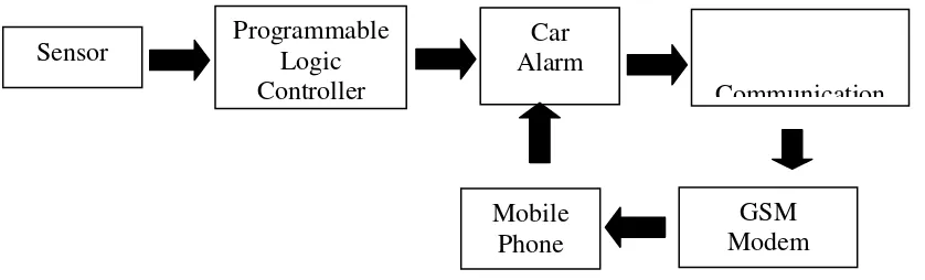
The block diagram of this system is shown as below:
Figure 1.1: Block Diagram of the GSM Mobile Car Alarm System
Step 1: The car owner leaves the car, and presses remote control to arm the system, the car is now under alert condition.
Step 2: If the car door is illegally opened, or the car is vibrated, an alarm signal will be sent out to the preset mobile phone immediately and automatically. Meanwhile, the siren of the car alarm will warn the burglar by making a loud sound.
Step 3: Upon receiving the alarm signal, the car owner can listen to the sound around the car, and judge that their car is in a danger condition and take an immediate action. Step 4: In case of robbery, the driver can leave the car safely and then use mobile phone to send out a command to lock the car.
Sensor
Communication
GSM Modem Mobile
Phone Programmable
Logic Controller
Car Alarm
1.2 OBJECTIVES
There are several objectives to be achieved:-
To understand the basic principles of Programmable Logic Controller (PLC), and Global System for Mobile Communication (GSM) modem.
To design the advanced auto anti-theft device that can protect the interest of car owners and safeguard the public security.
To design anti-theft security system via SMS.
To introduce the PLC application based on intelligent.
1.3 PROBLEM STATEMENT
Most of people today spent a lot of money to have a security system and also willing to spend more to maintain the vehicle by adding accessories to make their vehicle fine-looking. People use vehicles as transportation for work, study, entertainment or going to hospital in emergency cases. We realized that vehicle is not a symbol of luxurious anymore but own a vehicle today makes our live become more comfortable.
A vehicle owner's nightmare is when they went back to the car park and found out that their vehicle is no longer there. In some other cases, when the owner back to the vehicle, they noticed that the doors are unlocked, and found that the valuable things was disappeared. No matter where we park our vehicle, there is always a risk of it getting stolen nowadays. Vehicles can be stolen from parking lots in hotels, shopping complexes or public car parks. In fact vehicles parked in front of homes also disappeared!
A car security system has always been a matter of concern among vehicle owners and has become a booming industry by itself. Advancement in technology enables new and more innovative methods of vehicle safety to be introduced into the market. Today‟s vehicle security systems mostly only have to lock or unlock the door and sounding the siren in the case of intrusion. The siren can only alert those who are near the vehicle during an emergency and this shows that the existing security systems sometimes are not effective. By improving the existing system a sophisticated car security alarm system is required. This system enables information to be sent via SMS to the vehicle owner immediately if intrusion has occurred. The user can then lock the car‟s door by sending back a SMS.
This new generation of vehicle anti-theft device firstly adopts wireless data communication technology in the field of GSM car alarm system, and has achieved the technological breakthrough and eventually turned the wireless connection of GSM car alarm into reality. It is a most advanced auto anti-theft device that can protect the interest of car owners and safeguard the public security. It could be placed at any hidden place of vehicle due to its wireless connection, and thus enable it hard to be found by burglar and efficiently assured of the normal operation of the system.
1.4 SCOPE AND ORGANIZATION
There are several processes was involved in order to complete this „GSM Mobile Car Alarm System‟. This is a continuous process to ensure the quality and the functionality of this system. This system consists of several devices such as Program Logic Controller (PLC), Global System for Mobile Communication (GSM) modem, Interface Module, and Antenna.
Besides the components and devices, two softwares are used to complete this system. Proteus 6 Professional is software used to design the circuit diagram on a PCB Board. Whereby, Software Zelio soft 2 is used to create the PLC program, which enables a SMS to be sent through mobile phone. For this design, it uses six pushbuttons that will react as a switch. Four switches will be applied at the door and another two is needed for the booth and bonnet. If any switch is ON, it will immediately trigger the alarm. Below is the list of input and output of this system:-
Input: Ultrasonic Sensor, Shock Sensor, Pushbutton
Output: Siren, Light
There are two types of sensor circuit are applied in this project:-
a) Ultrasonic Motion Detector/Sensor Circuit
This circuit is one of the security alarm circuit which it will captures and evaluates any movements in the vehicle interior. It is a good circuit for detecting intruder and turning on the light, siren and etc. The sensitivity is adjustable via user‟s control.
b) Shock Sensor Circuit
The shock sensor is one of the primary theft detectors for a car security system. This type of circuit is implemented in this system which will response when detecting a force or shock. For every small shift on the vehicle for example moving the tyre off the car, it will be detected by this sensor and ultimately turning on the siren, light to give a warning sign. This circuit is used as an input to the PLC.
Below is the function of the additional devices used in this system:-
a) GSM Network
This design is fitted with a mobile telephone SIM card which allows the alarm to make and receive telephone calls. This also allows the owner to track the location of the car via the telephone signal. Any sim card can be used.
b) Door lock/unlock remote
The door can be lock/unlock by using a telephone or by transmitter. Once the alarm is triggered, the owner can take an action by sending a SMS to lock the car.
c) Telephone Alarming
Alarming telephone numbers can be registered on the alarm. If the alarm is triggered, the alarm will automatically send a SMS to the telephone number. This is an addition to the regular alarm (flashing lights, siren).
d) Antenna
In this project, antenna is used in order to propagate a signal. It is important because the signal from antenna will allow the user to control the vehicle from anywhere.
CHAPTER 2
LITERITURE REVIEW
2.1 CHAPTER OVERVIEW
This chapter explains the research related to the background of car alarm system, wireless communication system and how this knowledge can be applied to develop an advanced car alarm system. Next, the basic information about components will be discussed briefly including GSM Modem, Antenna, PLC and Communication Interface. This chapter will increase deeper understanding about basic wireless communication system and the components.
2.2 BACKGROUND
Even though technology plays a main role in developing good automated smart switching module but still there are many addicts who are concern on the price tag (costing) of the device itself.
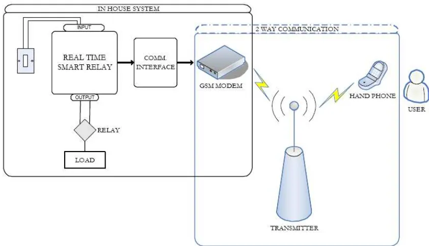
[image:24.612.116.537.336.577.2]Looking into all this aspect in the real life habit, a stable and acceptable solution which is the PLC base car security alarm system for remote access and via GSM modem has been designed. This project is to develop a smart switching system for car alarm using Real Time Programmable Logic Controller (PLC). Equipped with the latest technology, this system has the potential to become a reality in the new market. The functional block diagram of the GSM Mobile Car Alarm System is as shown below in Figure 2.1.
Figure 2.1: PLC base car alarm system functional block diagram