UNIVERSITI TEKNIKAL MALAYSIA MELAKA
DESIGN AND SIMULATION OF MULTIPLE DRILLING END
EFFECTOR
Report submitted in accordance with partial requirements of the Universiti Teknikal Malaysia Melaka for the Bachelor of Manufacturing Engineering
(Robotics & Automation) with Honours.
by
SITI ZURAIDAH BINTI MOHD ISA
DECLARATION
I hereby, declared this report entitled “DESIGN AND SIMULATION OF MULTIPLE DRILLING END EFFECTOR” is the results of my own research except as cited in references.
Signature : ……….
Author’s Name : SITI ZURAIDAH BINTI MOHD ISA
APPROVAL
This report is submitted to the Faculty of Manufacturing Engineering of UTeM as a partial fulfillment of the requirements for the degree of Bachelor of Manufacturing Engineering (Robotic & Autiomation) with Honours. The member of the supervisory committee is as follow:
……… Mrs.Silah Hayati Binti Kamsani
Project Supervisor
ABSTRACT
ABSTRAK
ACKNOWLEDGEMENT
I would like to express my gratitude to all those who gave me the possibility to complete this report. I am deeply indebted to my supervisor Puan Silah Hayati Binti Kamsani for all the guidance and critics given to me directly or indirectly, and also her sacrifice in time to teach and explain to me without a word of complains. I want to thank to my family for all their help, support, interest and valuable hints. My friend was of great help in difficult times.
2.3.1 Classes of drills 14-15
3.2 Project Understanding 31
3.3 Literature Review 32
3.4 Flow Chart 33
3.5 Conceptual Design 34
3.6 Factor Design of Multiple Drilling End Effector 34
3.7 Design Analysis 35
4. RESULT
4.1 Preliminary Design 37
4.2 Final Design 39
4.3 Material Selection 39
4.3.1 Cost 40
4.3.2 Strength 40
4.3.3 Final Material Selection 40-41
4.4 Analysis 41
4.4.1 Surface Curvature Analysis 41-42
4.4.2 Von Mises Stress 42-44
4.5 Simulation 45
5. DISCUSSION 46-47
6. CONCLUSION 48
LIST OF TABLES
2.1 Classes of Drills 15
2.2 Several Types of Drills 18
2.3 Recommendations for Speeds and Feeds in Drilling 19
4.1 Numbers of Component 39
4.2 Material and Its Yield Strength Value 40
4.3 Material of Component 41
4.4 Analysis Result of Surface Curvature 42
LIST OF FIGURES
2.1 Basic robot system 5
2.2 Robot controller block diagram 7
2.3 Robot teach pendant 8
2.14 Robotic turret tool with turret shaft and stepper motor 23 2.15 Programmable vision guide robotic turret 24
2.16 Typical PM servo motor 25
2.17 Stepper motor 26
2.18 Compressive Stress 28
2.19 Shear Stress 28
3.1 Process Flow of Designing End Effector 34
3.2 Process Flow of Analysis 35
3.3 Process Flow of Simulation 36
4.1 Preliminary Design of Multiple Drilling End Effector 37 4.2 Final Design of Multiple Drilling End Effector 38
4.3 Gaussian Analysis 41
4.4 Von Mises Stress for Mounting Plate 43
4.5 Von Mises Stress for Tool Holder 44
LIST OF EQUATION
2.1 Stress 27
2.2 Compressive Stress 28
2.3 Shear stress 29
2.4 Area of the rivet 29
2.5 Shear Stress 29
2.6 Shear Stress 29
2.7 F.O.S 29
CHAPTER 1
INTRODUCTION
1.1 Project Background
Hole making is among the most important operations in manufacturing, and drilling is a major and common hole making process. Most products whether it is small or large, in vast majority have several holes in them. Holes typically are used for assembly with fasteners such as bolts, screws and rivets, each of which requires a hole or for the design purpose such as weight reduction, ventilation, access to the inside parts, or for appearance.
Drilling can be defined as the operation of producing a hole by removing metal from solid mass using a cutting toll called a twist drill (Krar, etc al 1969). Although many other processes contribute to the production of holes, including boring, reaming, broaching and internal grinding, and the drilling accounts for the majority of holes produced in the machine shop. This is because it is simple, quick and economical. The other methods are used principally for more accurate, smoother, larger holes. They are often used after a drill has already made the pilot hole. The multiple drilling is common in industry, which is vastly used for CNC machine and the application of multiple drilling is used to increase the productivity, reduce time, minimum cost, and increase the accuracy.
challenge; their torque, speed, and possibility of breaking make them difficult to monitor robotically and require sensors for this monitoring.
In this project, all aspects with regards to design the multiple drilling end effectors for the purpose of drilling holes at the material will be discussed. The design should be consider on type of drilling process for example centering, drilling, reaming, tapping, counterboring, countersinking, and spotfacing. Then finite the analysis of design and lastly the simulation model will be developed.
1.2 Problem Statement
Drilling is a simple and easy process in industry, the problem that we can state on robotic drilling is the time that taken during change the tool bit, and when it have multi task of drilling processes for example first before making a hole we need to do a centering process, then we change the tool bit for the next process to drill a hole as instructed size. The problems that need to solve during this project is, to minimize the delay time during changing the tool bit.
1.3 Project Objective
The objective of this project is:
• To design the multiple drilling end effectors suitable for COMAU robot, that can solve the industrial problem.
1.4 Scope of Project
CHAPTER 2
LITERATURE REVIEW
2.1 Industrial Robot
Rehg (2000) explained that a robot is an automatically controlled, reprogrammable, multipurpose, manipulative machine with several reprogrammable axes, which may be either fixed in place or mobile for use in industrial automation applications. The key words are reprogrammable and multipurpose, because most single purpose machines do not meet these two requirements. Reprogrammable implies two elements; first the robots motion is controlled by a written program and second, the program can be modified to change significantly the motion of the robot arm in real time. Programming flexibility is demonstrated, for example, when the pickup point for a randomly placed part is located by a vision systems camera, and the program is changed while the robot arm is moving to the part. Multipurpose means a robot must be able to perform many different functions, depending on the program and tooling currently in use. For example, in one company a robot could be tooled and programmed to do welding, and in a second company the same type of robot could be used to stack boxes on pallets.
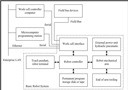
2.1.1 Robot System
Work cell controller
computer Field bus devices
Microcomputer programming station
Work cell interface External power unit hydraulic pneumatic
Robot controller Robot mechanical
arm
with attached teaching device, work-cell interface and program storage device. In addition, a source for pneumatic or hydraulic power is a part of the basic system. The work cell controller and other external devices that are part of the manufacturing system connect to the robot through the robot work-ell interface.
Figure 2.1: Basic robot system (Regh, 2000)
2.1.1.1 Mechanical arm
Arm is a mechanical device driven by electric-drive motors, pneumatic devices, or hydraulic actuators. The basic drive elements will be either linear or rotary actuators. The combination of motions included in the arm determines the type of arm geometry present. The basic geometries include rectangular, cylindrical, spherical and jointed spherical.
2.1.1.2Production Tooling
The robot arm alone has no production capability, but the robot arm interfaced to production tooling becomes an effective production system. The tooling to perform the work task is attached to the tool plate at the end of the arm. The tool plate is usually part of the wrist. The tooling is frequently identified by several names. The terms used to describe tooling in general are end of arm tooling and end effectors. If the tooling is an open and closed mechanism to grasp parts, it is referred as a gripper.
2.1.1.3 External Power Sources
The external power required to operate a robot system includes sources to drive the arm motion (electrical, hydraulic or pneumatic) and electricity for the electronic controller. Because most of grippers are activated by compressed air, a source of compressed air is required for most system. Large robot arms using hydraulic actuators for motion require a hydraulic power source, and in some cases a compressed air source will also be necessary for the gripper. All electric drive arms require only electrical power for motion, but many need compressed airs for tooling.
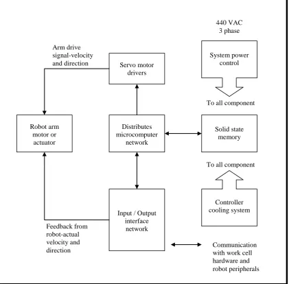
2.1.1.4 Robot Controller
Servo motor
direction Communication with work cell
hardware and robot peripherals
Figure 2.2: Robot controller block diagram (Regh, 2000)
2.1.1.5 Teach Stations
The teach stations on robots may consists of teach pendants, programming units, controller front panels, and DOS or windows based microcomputers. The teach pendant in Figure 2.3 is an example of a handheld terminal with a flat screen, multiline, touch sensitive display. Some robots permit a combination of programming devices to be used in programming the robot system whereas others provide only one system programming unit. In addition, some robots use DOS or windows based microcomputers as programming stations. Some robot vendors have programming units that are teach pendants with enhanced program creation and editing capability. All of the teach stations except the microcomputer support three
activities, first robot power up and preparation for programming, second entry and editing of programs and third is to execution of programs in the work cell. The development of a program includes keying in or selecting menu commands in the controller language, moving the robot arms to the desired position in the work cell, and recording the position and command in memory.
Figure 2.3: Robot teach pendant
2.1.2 Robot Manipulator Degree
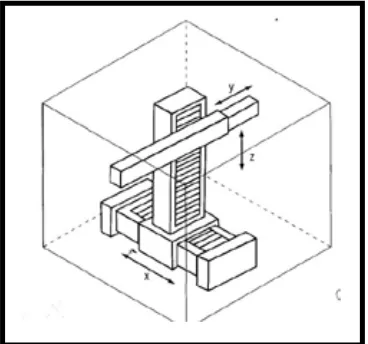
2.1.2.1Cartesian Robots
Cartesian robots have a common feature, in that; the first three joints corresponding to the major axes are prismatic (PPP), as seen in Figure 2.4. The advantages of Cartesian robots are that the configuration and design are simple, three prismatic joints are decoupled, and the motion control in Cartesian space can be easily carried out. The large Cartesian robots, which resemble overhead gantry cranes, are called gantry robots.
Figure 2.4: Cartesian robot
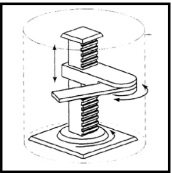
2.1.2.2Cylindrical Robots
Figure 2.5: Cylindrical robot
2.1.2.3Spherical Robots
A spherical robot is shown in Figure 2.6 below and the position of the wrist is determined by two rotations and one translation through two rotary joints and a prismatic joint (RRP). Theoretically, two rotational angles could change between 0 and +360 degrees, the work space should be between a spherical surface and a cylinder. In practice, the minimum height of arm above floor level is h. Therefore, the workspace is between a semi spherical surface and a cylinder. The reader is asked to draw the work space of the spherical robot.