Faculty of Electrical Engineering
SHADING ANALYSIS FOR DESIGN OF PV POWER PLANT
Vinodh A/L Annathurai
Bachelor in Electrical Engineering (Industrial Power)
SHADING ANALYSIS FOR DESIGN OF PV POWER PLANT
VINODH A/L ANNATHURAI
A report submitted
in partial fulfillment of the requirements for the Bachelor in Electrical Engineering (Industrial Power)
Faculty of Electrical Engineering
UNIVERSITI TEKNIKAL MALAYSIA MELAKA
ii
DECLARATION
I declare that this report entitle “Shading Analysis for Design of PV Power Plant” is the result of my own research except as cited in the references. The report has not been accepted for any degree and is not concurrently submitted in the candidature of any other degree.
Signature : ...
Name : VINODH A/L ANNATHURAI
iii
APPROVAL
I hereby declare that I have read through this report entitle “ShadingAnalysis for Design of PV Power Plant” and found that it has complied the partial fulfillment for awarding the Bachelor in Electrical Engineering (Industrial Power)
Signature : ...
Supervisor’s Name : DR. GAN CHIN KIM
iv
DEDICATION
v
ACKNOWLEDGEMENT
First of all, I would like to thank all the good people who have helped me in various ways to complete my Final Year Project.
My utmost gratitude goes to my main project supervisor Dr. Gan Chin Kim for continued patience and guidance, and for incredible expertise that he brings to all phases of the project. I highly appreciate his valuable time in giving me useful ideas to complete this project.
Very special thanks to all my course mates, who have provided insights into both the topic and technical guidance in this compilation. Cooperation between my class members helps me so much. The information that we have exchanged with each other ease the way of my project completion.
vi
ABSTRACT
PV system is environment friendly which is designed to reduce consumption of electricity from non-renewable energy sources. However, the PV system is exposed to weather conditions causing declination in power generation efficiency. Shading of photovoltaic modules is a widespread phenomenon which affects the performances of the PV system. In accordance to it, this research aims to improve the shading factors which will affect the performances of photovoltaic (PV) system in the solar power plant. Shading of solar cells not only reduces the cell power PMPP, but also changes the open circuit voltage VOC, short circuit
current ISC, fill factor and its efficiency. The objective of this research is to design a PV power
vii
ABSTRAK
viii
ix
2 LITERATURE REVIEW
2.1 Introduction 4
2.2 Theory and the Basic Principles 4
3 METHODOLOGY
3.1 Introduction 19
3.2 Methods or Techniques 20
3.3 Description of the work to be Undertaken 32
4 RESULTS AND DISCUSSION
4.1 Introduction 34
4.2 Specific Energy 35
4.3 Photovoltaic (PV) Energy Reduction 40
4.4 Analysis and Data Validation 45
4.5 Discussion and Finalisation of the Data 54
5 CONCLUSION
5.1 Conclusion 61
5.2 Recommendation 63
x
LIST TABLES
TABLE TITLE PAGE
3.1 Size of Power Plant with the Parameters 26
4.1 Total Irradiation(Solar Pro Software) 46
4.2 Comparison of the Total Irradiation from the Solar Pro and
the Metonorm 47
4.3 The Sun Hours and the AC Energy(SPF) 51
4.4 Summarise of Peak Sun Hour in Melaka (PSH) 52
4.5 Height of the Building with a Distance of 20m by 20m PV
Power Plant With No Shading 55
4.6 Height of the Building with a Distance of 40m by 40m PV
Power Plant With No Shading 56
4.7 Height of the Building with a Distance of 60m by 60m PV
Power Plant With No Shading 57
4.8 Height of the Building with a Distance of 80m by 80m PV
Power Plant With No Shading 58
4.9 Height of the Building with a Distance of 100m by 100m PV
Power Plant With No Shading 59
4.10 Distance of the Building from the PV Power Plant in Terms of
xi
LIST FIGURES
FIGURE TITLE PAGE
2.1 A Utility-Connected PV System 5
2.2 The Grid Connected PV System 5
2.3 The Surrounding Plant and Guano Shading Phenomenon 7
2.4 Front Row Shading Phenomenon 7
2.5 The Nearby Power Distribution Room and Wire Pole Shading
2.10 The Equivalent Circuit of the Double-Diode Model 14
2.11 The Bypass Diode Model 14
2.12 A Simple Energy Recovery Circuit 16
2.13 Array Configuration for Alleviating the Power Loss Under the Partial Shading Conditions. (a) SP, (b) TCT, and (c) BL.
17
2.14 The Series-parallel PV System with Bypass Diode 18
2.15 The New Added Circuit 18
3.1 Azimuth Angle and Tilt Angle 21
3.2 Angular Displacement 21
3.3 Tilt Angle 22
3.4 Name Plate Label of NA-V135H5 23
xii
3.7 A House Shaped Building beside the 20m by 20m PV Power Plant 27 3.8 A House Shaped Building beside the 80m by 80m PV Power Plant 27
3.9 3D CAD and Designing of the Building 28
3.10 An I-V Curve 29
3.11 Electric Power Calculation 30
3.12 A Solar Pathfinder 31
3.13 Flow Chart of Work to be Undertaken 33
4.1 PV Energy versus Distance of Building from the 20m by 20m Power Plant
35
4.2 PV Energy versus Distance of Building from the 40m by 40m Power Plant
36
4.3 PV Energy versus Distance of Building from the 60m by 60m Power Plant
37
4.4 PV Energy versus Distance of Building from the 80m by 80m Power Plant
38
4.5 PV Energy versus Distance of Building from the 100m by 100m Power Plant
39
4.6 Energy Reduction versus Distance of Building from the 20m by 20m Power Plant
40
4.7 Energy Reduction versus Distance of Building from the 40m by 40m Power Plant
41
4.8 Energy Reduction versus Distance of Building from the 60m by 60m Power Plant
4.11 PSH in Malaysia’s Stations 49
4.12 The 15m FKE Building 50
xiii
MPPT Maximum Power Point Tracking
PR Performance Ratio
PSH Peak Sun Hour
PV Photovoltaic
RE Renewable Energy
SEDA Sustainable Energy Development Authority
SPF Solar Path Finder
1
CHAPTER 1
INTRODUCTION
1.1 Research Background
At present, electrical energy plays an important role in our daily life. Most of the electrical energy is produced by fossil fuels and nuclear energy. Since these kinds of energy sources are exhaustible, many countries have started to promote and practice the renewable energy. Among all the renewable energy, solar energy has higher demand than others. The photovoltaic (PV) system is installed to convert the solar energy to electrical energy. However; few main factors influences the performances of the PV system. The shading phenomenon is one of the main problems that decrease the PV performances. This research is carried out to study the analysis of shading effect of the nearby buildings in PV module by using Solar Pro simulation method. These findings will give a clear view for the PV system installer in setting up any solar power plant in Melaka area with the coordinate of 2.2oN,
2
1.2 Problem Statement
The main aim of this research is to improve the shading factors which will affect the performances of photovoltaic (PV) system in the solar power plant. The major factor affecting the performance of this PV system is the shading phenomenon. There are several types of shading phenomenon in PV system; the front row PV array shading phenomenon, the height and distance of the surrounding buildings shading phenomenon and the nearby power distribution room and wire pole shading phenomenon. This research is carried out to ensure that the exact height and distance of surrounding buildings of the solar power plant which is free from shading that improves the performance of the PV system. The shading analysis and the system improvement are conducted by the simulation assisted by the Solar Pro software.
1.3 Objectives
The main objectives of this project are;
To identify the suitable distance between the surrounding building and solar power plant which minimizes the shading factor.
3
1.4 Scope of Work
This research focuses on the shading analysis of the surrounding building towards the PV power plant which is situated in the flat ground base. The distance of the surrounding building from the power plant and the height of surrounding building are considered as the shading phenomenon. The main aim of the research is to improve the performance of PV system by minimizing the shading factor. The solar panel is facing towards south and designed in Melaka with the coordinate of 2.2oN, 102.25oE. The house-shape building size is 20m by 20m which is kept constant with the varied height and placed in east and west direction of the power plant. The PV power plant is only designed for the size of 400m2, 1600m2, 3600m2,
6400m2 and 10000m2 with the maximum capacity of 16.2kW, 58.32kW, 126.36kW,
233.28kW and 356.40kW respectively. The Solar Pro software is used to simulate the shading analysis process.
1.5. Expected Project Outcome
4
CHAPTER 2
LITERATURE REVIEW
2.1 Introduction
This chapter will discuss the theoretical background of the project. The theoretical background will explore the basic history, analysis of solar shading, and simulation software review, especially Solar Pro and Solar Pathfinder that were used in this project. In the basic principles part the types of shading, the effect of the photovoltaic shading array, influence of shading on the electrical parameters and methods to mitigate the shading problem were explained.
2.2 Theory and the Basic Principles
This part will be discuss the theory and the basic principles of the photovoltaic principles, types of shading, the effect of the photovoltaic shading array, influence of shading on the electrical parameters and methods to mitigate the shading problem.
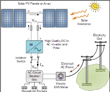
2.2.1 Photovoltaic System
5
components needed to convert solar energy into electricity usable loads. The PV system is a distributed system, which generates the small amount of power to the consumers. A utility-connected PV system is the most common system design. Figure 2.1 and Figure 2.2 show the common system of PV configuration and its Grid-Connected system respectively.
Figure 2.1: A Utility-Connected PV System
6
2.2.2 Types of Shading
There are many factors influencing the performance of this system during the real installations of Photovoltaic (PV) system. Shading is one of the main factors which influence the performance of PV system. There are many types of shading phenomena in a PV system, and it can be divided into the following categories after long time surveys and observation on one large ground-based grid connected PV system [1].
1. The surrounding plant and guano (bird drop) shading phenomenon (Figure 2.3). 2. The front row shading phenomenon (Figure 2.4).
7
Figure 2.3: The Surrounding Plant and Guano Shading Phenomenon
8
2.2.3 The Effect of Photovoltaic Shading Array
A PV system comprises of many PV modules that are connected in series and parallel way. If the array layout is irrational or there are shades around the arrays, shading will occur in some modules [1]. In practical condition, a module with shading in a long series will not generate photovoltage, while other modules in the same series still produce voltage normally. So there is current going through this shaded module [2,3].
2.2.4 Influence of Shading on the Electrical Parameters
The shading in the photovoltaic can effect in disproportional high losses in performance. Shaded solar cells are frequently driven in the negative voltage range. The annual loss in a performance in some systems is more than 10% [4]. The influence of cell shading on electrical parameters are the short circuit current Isc, open circuit voltage Voc, fill
factor, maximum power point PMPP and efficiency [4,5]. Figure 2.6is a simple example of the
solar system which obtains all the electrical parameters.
9
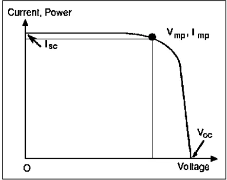
i.) 2.2.4.1 Current-Voltage (I-V) Curves
The current-voltage (I-V) characteristic is the basic electrical output profile of PV device. The I-V characteristic represents all possible current-voltage operating point (and power output) for a given PV device (cell, module, or array) at a specified condition of incident solar radiation and cell temperature [4,5]. Figure 2.7 shows an I-V curve, which illustrates the electrical output profile of a PV cell, module or array at a specific operating condition [4,5, 6].
A PV device can function at any place along its I-V curve, depending on the electrical load. At any specific voltage on an I-V curve there is an associated current, and this operating point is known as an I-V pair.
10
2.2.4.2 The Basic I-V Curve Parameters. i.) Open circuit voltage
The open circuit voltage Voc is the maximum voltage on an I-V curve and is the
operating point of a PV device under infinite load or open circuit condition, and no current output [4].
V(at I=0) =Voc (2.1)
Voc is also the maximum voltage difference across the cell for a forward-bias sweep
in the power quadrant [4-7].
VOC= VMAX for forward-bias power quadrant (2.2)
ii.) Short circuit current
The short circuit current Isc is the maximum current on an I-V curve and is the
operating point of a PV device under no load or short circuit condition, and no voltage output. Since the voltage is zero at the short-circuit current, the power output is also zero. I (at V=0) = Isc. For an ideal solar cell, this maximum current
value is the total current generated in the solar cell by photon excitation. Isc =IMAX =
Iℓ for forward-bias power quadrant [4-7].
iii.) Maximum power point