UNIVERSITI TEKNIKAL MALAYSIA MELAKA
Design and Development of Shimless Pump
Footing System
Report submitted in accordance with the requirements of the Universiti Teknikal Malaysia Melaka for the Bachelor Degree of Manufacturing Engineering in
Manufacturing Process
By
Mohd Faiz Haji Abdul Haji
UTeM Library (Pind.1/2007)
UNIVERSITI TEKNIKAL MALAYSIA MELAKA
BORANG PENGESAHAN STATUS LAPORAN PSM
JUDUL:
An Experimental Study of The Impact of Surface Grinding Parameter
On Flatness
SESI PENGAJIAN: Semester 2 2007/2008
Saya Mohd Faiz Abdul Haji
mengaku membenarkan laporan PSM / tesis (Sarjana/Doktor Falsafah) ini disimpan di Perpustakaan Universiti Teknikal Malaysia Melaka (UTeM) dengan syarat-syarat kegunaan seperti berikut:
1. Laporan PSM / tesis adalah hak milik Universiti Teknikal Malaysia Melaka dan
penulis.
2. Perpustakaan Universiti Teknikal Malaysia Melaka dibenarkan membuat salinan
untuk tujuan pengajian sahaja dengan izin penulis.
3. Perpustakaan dibenarkan membuat salinan laporan PSM / tesis ini sebagai bahan
pertukaran antara institusi pengajian tinggi.
4. *Sila tandakan (√)
SULIT
TERHAD
/ TIDAK TERHAD
(Mengandungi maklumat yang berdarjah keselamatan atau kepentingan Malaysia yang termaktub di dalam AKTA RAHSIA RASMI 1972)
(Mengandungi maklumat TERHAD yang telah ditentukan oleh organisasi/badan di mana penyelidikan dijalankan)
i
DECLARATION
I hereby, declare this report entitled “Design and Development of Shimless Pump Footing System” is the results of my own research except as cited in references.
Signature : ……….
Author‟s name : ……Mohd Faiz Haji Abdul Haji………..……...
APPROVAL
This PSM submitted to the senate of UTeM and has been as partial fulfillment of the requirements for the degree of Bachelor of Manufacturing Engineering (Manufacturing
Process). The member of the supervisory committee is as follow:
………
Mr. Mohd Shahir Kasim Project Supervisor
iii
ABSTRACT
ABSTRAK
Projek ini bertujuan untuk mengkaji masalah „soft foot‟ yang menyebabkan susunan system
pam mesin menjadi tidak lurus. Setelah itu, sebuah rekaan sistem kaki yang tidak ber‟shim‟ akan direka untuk mengatasi masalah „soft foot‟ ini. „Soft foot‟ ini terjadi apabila ada jarak
di antara kaki pam mesin dan tapak asasnya. Pam mesin ini akan bergerak dari kedudukan
asalnya walaupun nat telah diketatkan untuk mengelakkannya. „Soft foot‟ juga
menghasilkan garis tekanan pada mesin kerana kaki yang pendek diikat pada tapak asa dengan menggunakan nat. sekiranya ia tidak diperbaiki, hasil yang dihasilkan menjadi tidak berkualiti. Proses rekaan ini akan menggunakan CAD, iaitu Solidwork. Dengan
menggunakan perisian ini, sistem tidak ber‟shim‟ ini dapat dihasilkan dan diperhatikan untuk memastikan ia boleh mengatasi „soft foot‟. Sistem ini juga perlu mempunyai tapak
asas supaya ia tidak lagi bergantung pada „shim‟ untuk meluruskan system pam mesin. Rekaan ini memudahkan proses pelurusan dan masalah „soft foot‟ dapat dikurangkan.
Kemudian, selepas system ini telah reka, ia akan di analisis untuk mengkaji kesannya ke
atas „soft foot‟ ketika proses meluruskan. Pemerhatian akan dibuat sama ada system ini berkesan ataupun tidak dibandingkan dengan „shim‟ biasa. Ada dua cara asas untuk mengesan „soft foot‟ akan digunakan iaitu „frame distortion index‟ and „the laser soft foot locator‟. Ia meramalkan yang masalah „soft foot‟ boleh dihapuskan dimana „misalingment‟
v
DEDICATION
My parents,
Haji Abdul Haji Md Dangi
Hajah Sarah Abd Wahab
My beloved sibling,
Lily Harnisa Abdul Haji
Hanis Yusri Abdul Haji
Hairul Faizi Abdul Haji
ACKNOWLEDGEMENTS
First of all, Alhamdulillah, praise to Allah as I have completed my PSM 1 and 2. First and foremost, I would like to thank my beloved parent, Haji Abdul Haji Md Dangi and Hajah Sarah Abd Wahab for their full concern, encouragement and considerate. As well, I would like to state thankfulness to Encik Mohd Shahir Kasim, my PSM Supervisor, for his assistance and custody, together with training that I had learned. Besides, I want to thank to all lecturers of Faculty of Manufacturing Engineering, UTeM and staffs.
Secondly, my appreciation goes to those who have helped me during this thesis for their involvement, especially to Encik Fendi, technician of CNC Laboratory his assistance. Not forgotten, to my friend, Ahmad Anwar Hamdan for being helpful during the designation process.
Last but not least, for my course mate, BMFP 04-08, who are being supportive, helpful and sharing during studying in UTeM.
Wassalam,
vii
1.7.1 The effect of Soft Foot on Alignment...7
1.7.2 The minimum thickness shimless for soft foot…………..8
1.7.3 Difficulties in performing alignment……….8
1.7.4 Cost of Alignment……….11
1.7.5 Material……….11
1.8Overview……….12
1.8.1 The relation between soft foot and shaft alignment……..12
2.0LITERATURE REVIEW
2.1Introduction………...14
2.2 Types of soft foot………...………...15
2.2.1 Deflection and damage cause by soft foot………17
2.2.2 Soft foot Checks and Corrections………….………..…..19
2.2.2.1 Soft Foot Checks………...19
2.2.2.2 Soft Foot Corrections………21
2.2.3 Other method to Check Soft Foot ………...….23
2.2.3.1 Frame distortion index………...…...23
2.2.3.2 Laser soft foot locator………...……24
2.3 Vibration………26
2.4 Shaft Alignment……….29
2.4.1 Basic of shaft alignment…….………….………..29
2.4.2 Shaft alignment procedure……….30
2.4.3 Importance of alignment………31
2.4.3.1 Rough soft foot correction……….31
2.4.3.2 Rough alignment………32
2.4.3.3 Final soft foot correction………32
2.4.3.4 Final alignment………...32
2.4.3.5 Problem arising from poor alignment……….33 2.4.3 Offset alignment……….34
2.6.1 Application of shim………41
2.6.2 Limitation / Disadvantage of Shim………43
2.7 Design matrix………...45
ix
3.3.1 Project planning……….…….56
3.3.2 Design analysis……….…..57
3.3.3 Conceptual design……….……..58
3.3.3.1Concept 1……….…...58
3.3.3.2Concept 2………....59
3.3.3.3Concept 3……….…...60
3.3.4 Design selection……….….61
3.3.5 Selection material……….…..61
3.4Software CAD (SolidWorks)………...62
4.2.1 Design analysis Part 1……… ……….74
4.3Part 2………..79
4.3.1 Design analysis Part 2………..80
4.4Part 3………..84
4.5Assembly ………....89
4.6Calculation movement………....…92
4.6.1 Vertical and horizontal movement………....92
5.0DISCUSSION 5.1Introduction……….……93
5.2Design……….….…...93
5.3Material………...94
5.4Calculation………..94
5.5Vibration………..………...95
5.6Machining………..……….95
5.7Advantage………...96
6.0CONCLUSION 6.1Conclusion………..………97
6.2Recommendation………..………..98
REFERENCE………...99
xi
LIST OF FIGURES
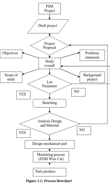
1.1 Process flowchart 4
1.2 Show the reading on of the pump 7
1.3 Show the angular misalignment 9
1.4 Effect on shaft caused by misalignment 10
2.1 Common Types of Soft Foot 15
2.8 Measure soft foot with feeler gauge and fill gap completely 21
2.9 Checking for softfoot 22
2.10 Step shimming 22
2.11 Measurement of vertical shift 24
2.12 Before the loosening sequence 27
2.13 After the loosening sequence 27
2.14 Phase relationship can show differences between vertical measurements on the bolt,
machine foot, base plate or base 28
2.15 Flow chart for shaft alignment process 30
2.16 Soft foot to be corrected 32
2.17 Offset misalignment 35
2.18 Example of an acceptable misalignment for an 1800 rpm machine 36
2.19 Angular misalignment 37
2.21 Stainless steel precut shim packs 41
2.22 Relief valve 42
2.23 Shim mounting 43
2.24 Baseplate Grouting 44
2.25 Screen shot captured from a SolidWorks top down design approach 47
3.1 High-level problem solving during early design 54
3.2 Flow chart important steps in design 56
3.3 The importance of material selection in product development 61
3.4 Final design 63
3.5 Before cutting 63
3.6 Machine set up according to dimension 64
3.7 The workpiece was clamped properly 64
3.8 Control the speed rate 65
3.9 Cutting the length of workpiece 65
3.10 Finished workpiece 66
3.11 Cutting the width of workpiece 66
xiii
4.10 Front view 81
4.11 Right view 81
4.12 Top view 82
4.13 Bottom view 82
4.14 Isometric view 83
4.15 Isometric drawing 84
4.16 Isometric drawing 85
4.17 Front view 86
4.18 Right view 86
4.19 Top view 87
4.20 Bottom view 87
4.21 Isometric view 88
4.22 Isometric view 89
4.23 Front view 90
4.24 Right view 90
4.25 Top view 91
LIST OF TABLES
1.1 Gantt chart 5
2.1 Laser Soft Foot Locator Results 25
2.2 Table of Maximum Allowable Offset 35
2.3 Maximum Allowable Angularity 37
1
CHAPTER 1
INTRODUCTION
1.1 Introduction
In theory, machine alignment is a straightforward process, but in real world applications, it is often compounded by structural faults such as soft foot, piping strain, induced frame distortion, excessive bearing clearance or shaft rubs.
For this project, it will examine how to eliminate soft foot which is some of the typical reasons why alignments are unsuccessful. In theory, machine alignment is a very straightforward process. With some type of measuring device extended across the coupling, the shafts are rotated to several positions (at least three) to determine the relative position between them (Skeirik R. D., 1997). Since alignment is an iterative process, which meaning that the misalignment should continuously decrease with each machine move, it is theoretically only a matter of sufficiently repeating alignment corrections until an acceptable solution is achieved.
In fact, quality alignment is not dependent on the type of measurement system used but dependent on how to solve problems happen in the alignment. Any good dial indicator set or laser system should be sufficient method to perform quality alignments.
To prevent any soft foot problems occur, the installed of the shim must done by personnel that has enough trained in mechanical seal installation practices. The other definitely limitation or disadvantages of shim such as material properties that using to construct the shim. Regarding to material properties, influence corrosion factor is very important to keep up the material strength in good condition. Stated that not all type of materials can be used for shimmed the pump. Although the steel materials are very strong but there are some type of steels can be easily become corrosion. This can limit the performance function for shim (Goulds Pumps (2002)).
1.2 Objective
a) Analyse effect on softfoot during alignment process.
b) Study and develop shimless system that can overcome the problem.
1.3 Scope of study
3
analyse the effectiveness of shimless unit compare to conventional shim in rectifiying misalignment problem.
1.4 Report Organization
This thesis consists of six chapters:
Chapter 1: Introduces of Shaft Alignment, the effect of soft foot on alignment, problem arises in industry which drive to develop the better shimless, objective and scope of this project.
Chapter 2: Literature review from journal, books and internet. The area covered including principle for shaft alignment, method in alignment, procedures, tolerance etc.
Chapter 3: Describes methodology to develop the system, the requirement to ensure the design of shimless, selection material etc.
Chapter 4: Result of design that has been obtained.
Chapter 5: Discussion on reliability of product design and improvement.
Chapter 6: Conclusion for the whole project and recommendation for future work.
5 1.6 Gantt Chart
7 1.7 Problem Statement
1.7.1 The Effect of Soft Foot on Alignment
The soft foot in one of the problems and challenges for plant operations and maintenance personnel. It is the common term for machine frame distortion, soft foot is caused when one or more feet of machine are shorter, longer or angled someway different than the rest of the feet. This non-uniformity causes stress on the machinery when the foot is forced into place by tightening the hold-down bolt (Hamernick I., 2006). The missing shims under a foot, a bend foot, or deteriorating base plate or foundation can cause this condition.
Figure 1.2: Show the reading on of the pump (McNally Institute (2005)
1.7.2 The minimum thickness shimless for soft foot
The bottoms of the machine feet shall rest on the base or foundation with 90 percent contact of the footprint (Wowk V., 2000). A 0.003 inch thick shim shall not penetrate under any foot with all hold down bolts loose. This is an unforeseen condition and will require more time to correct (Wowk V., 2000). Resonant foundations or bases are dynamic structural defects. This will cause high vibration at specific speeds. Resonances are not detectable during static alignment measurements.
A dial indicator, or other measuring devices, shall be fixture to measure the vertical rise at each foot as the hold down bolt is loosened. According to Wowk V. (2000), all other bolts shall remain tight. A rise of less than 0.002 inch is acceptable. A rise of more than 0.002 inch shall be corrected by adding shims. After shim changes are made, the above test shall be repeated at all feet until less than 0.002 inch rise is measured at each foot. If shim changes cannot adjust the rise, then the base will need to be ground or machined.
1.7.3 Difficulties in performing alignment