MOUSE PULSE DETECTOR CIRCUIT
NOOR ROHA BT ABDULLAH
MOUSE PULSE DETECTOR CIRCUIT
NOOR ROHA BT ABDULLAH
This report is submitted in partial fulfillment of requirements for the award of Bachelor of Electronics Engineering (Computer Engineering) With Honours
Faculty of Electronics and Computer Engineering Universiti Teknikal Malaysia Melaka
UNIVERSTI TEKNIKAL MALAYSIA MELAKA
FAKULTI KEJURUTERAAN ELEKTRONIK DAN KEJURUTERAAN KOMPUTER
BORANG PENGESAHAN STATUS LAPORAN PROJEK SARJANA MUDA II
Tajuk Projek : MOUSE PULSE DETECTOR CIRCUIT
Sesi
Pengajian : 2008/2009
Saya ………...NOOR ROHA BINTI ABDULLAH………. (HURUF BESAR)
mengaku membenarkan Laporan Projek Sarjana Muda ini disimpan di Perpustakaan dengan syarat-syarat kegunaan seperti berikut:
1. Laporan adalah hakmilik Universiti Teknikal Malaysia Melaka.
2. Perpustakaan dibenarkan membuat salinan untuk tujuan pengajian sahaja.
3. Perpustakaan dibenarkan membuat salinan laporan ini sebagai bahan pertukaran antara institusi
pengajian tinggi.
4. Sila tandakan ( √ ) :
SULIT*
(Mengandungi maklumat yang berdarjah keselamatan atau kepentingan Malaysia seperti yang termaktub di dalam AKTA RAHSIA RASMI 1972)
TERHAD* (Mengandungi maklumat terhad yang telah ditentukan oleh
organisasi/badan di mana penyelidikan dijalankan)
TIDAK TERHAD
Disahkan oleh:
__________________________ ___________________________________ (TANDATANGAN PENULIS) (COP DAN TANDATANGAN PENYELIA)
Alamat Tetap: NO. 9A KG. NYIOR, 23100 PAKA, DUNGUN, TERENGGANU
“I hereby declare that this report is the result of my own work except for quotes as cited in the reference”
Signature : ………
“I hereby declare that I have read this report and in my opinion this report is sufficient in terms scope and quality for the award of Bachelor of Electronic
Engineering (Industrial Electronics) With Honours”
Signature : ……….
Name : MR FARID ARAFAT BIN AZIDIN
ACKNOWLEDGEMENT
Alhamdulillah, finally I have been able to finish my Final Year Project within the allocated period successfully. First of all, I would like to express my greatest thanks to my supervisor, En. Farid Arafat bin Azidin for his cooperation, contribution and guidance toward the progress of this project. Thanks for his advise and effort to ensure the successfully completion of my final year project. My sincere acknowledgement to my beloved family especially may parent. Without their support and understanding this would not have been possible. My special appreciation and thank to my friends for their support and advice, and for their invaluable assistances towards this thesis project. Lastly, I would like to express my special thank to all individuals that involved either directly or indirect during completion of this final year project.
ABSTRACT
ABSTRAK
CHAPTER ITEM PAGE
II LITERATURE REVIEW
2.1 Introduction 6
2.2 Introduction to Detector 7
2.3 Sensor as Detector Element 7
2.3.1 Infrared Sensor 8
2.3.2 Photodiode Sensor 8
2.4 The Analysis of the Detector Circuit 9 2.4.1 Normal ECG Waveform 9 2.4.2 Pulse Detector Circuit 10
2.4.3 Pulse Detector Construction 11
III DESIGN METHODOLOGY
3.1 Chapter Overview 15
3.2 Project Plan Overview 15
3.3 Design pulse detector Circuit 18
3.3.1 Sensor 19
3.3.2 Operational Amplifier 20 3.3.3 Differential Amplifier 21 3.3.4 Instrumentation Amplifier 22 3.3.5 Transimpedance Amplifier Circuit 24
3.3.6 Filter 25
3.4 Fabrication Method 27
3.5 Testing and Troubleshooting 30
CHAPTER ITEM PAGE
4.3.2 Instrumentation Amplifier circuit
and Filter circuit 34
4.4 The Infrared Photodiode Transimpedance Circuit
Construction 36
4.5 Design Evaluation 40
4.6 The Result from Measuring Process 42
4.7 Filter 43
4.7.1 High Pass Filter 44
4.7.2 Low Pass Filter 45
4.8 Final Result of the Mouse Pulse Detector Circuit 46
V DISCUSSION
5.1 Signal Analysis 47
CHAPTER ITEM PAGE
VI CONCLUSION AND RECOMMENDATION
6.1 Conclusion 49
6.2 Recommendation 50
TABLE LIST
TABLE TITLE PAGES
3.1 Differences between photodiode and phototransistor 19 3.2
4.1
Features of IR emitter and IR receiver The estimation of the output voltage
FIGURE LIST
FIGURE TITLE PAGES
1.1 Process of the detector circuit 2
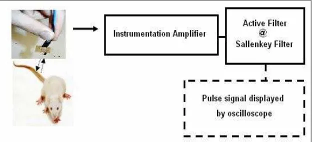
1.2 Block diagram on how detector circuit work 3
2.1 Normal ECG waveform 9
3.1 Project Planning and Methodology 16
3.2 Flow chart PSM1 and PSM2 20
3.3 The construction of the emitter and receiver circuit 17
3.4 IR emitter and IR detector 18
3.5 Pin connection of operational amplifier LM741 19
3.6 Instrumentation Amplifier 21
3.7 Transimpedance Amplifier circuit 22
3.8 Combination of Low Pass and High Pass filter 24 3.9 PCB ayout of Transimpedance circuit 27
3.10 PCB layout of Filter circuit 27
3.11 PCB board of the transimpedance circuit and filter circuit 28 3.12 The manufacturing process of PCB board 29
3.13 Procedure to test the circuit 30
3.14 Mouse Pulse Detector circuit prototype 31
4.1 Instrumentation circuit 33
FIGURE TITLE PAGES
4.7 Transimpedance circuit 36
4.8 Circuit prototypes 37
4.9 Circuit prototypes on PCB board 37
4.10 Testing circuit with active filter 38 4.11 Human Output voltages on oscilloscope 38
4.12 Active filter 38
4.13 Testing circuit with active filter 39 4.14 Human Output voltages on oscilloscope 39
4.15 Testing to a mouse 39
4.16 Mouse Output voltages on oscilloscope 40
4.17 Output voltages on oscilloscope 41
4.18 Emitter circuit 41
4.19 The human output voltage 42
4.20 First Order High Pass Filter 44
4.21 Second Order Low Pass Filter 45
APPENDIX LIST
NO TITLE PAGES
A High-Performance IR Emitter and IR PIN Photodiode in Subminiature SMT Package
51
CHAPTER I
INTRODUCTION
1.1 Project Introduction
Before this, the ECG, EEG and EMG – signal were introduced in bioelectrical signal which to detect the signal from human body like the brain, muscles and hearth. This bioelectric signal is measured from the surface of the skin that is mostly in range of 0-2000µV. In this project, a detector circuit will be constructed to detect a pulse signal from an animal which is a mouse. The same concept used in detecting human signal will be used in this project. The concept that will be used in designing this detector circuit is an amplifier concept.
1.2 Project Background
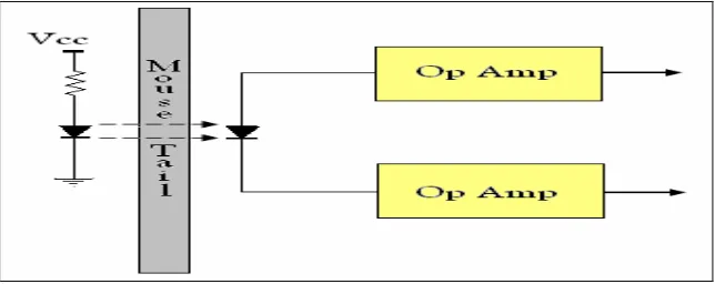
The basic concept of this detector circuit is the infrared light (875nm) are being transmitted through the skin and absorbed at the level of the wavelength by the electrical activities and blood contraction of the blood inside the body. This electrical activities and blood contraction allows more infrared light to pass through it. Thus, after the wavelength of light have been transmitted through tissue and received by a photodiode, the infrared light intensity is computed. The mouse pulse detector circuits design with a transimpedance circuit, which is the receiving circuits that convert the infrared light currents into voltages which can then be observed using an oscilloscope. The process can be illustrated by as a general schematic as in Figure 1.1 below:
Figure 1.1 Process of the detector circuit
1.3 Problem Statement
1.4 Objective
Due to the problem statement stated above, the aim of this project is to build a pulse detector circuit using an infrared photodiode sensor, which will be connected to an amplification circuit and then fed to an oscilloscope for observation. This pulse detector circuit will detects a mouse pulse using a principle of differential amplifier. This detector circuit used to detect an actual waveform of a mouse pulse signal. This pulse will be displayed on oscilloscope in range around 1.5s – 2.0s.
1.5 Project Scope
A mouse pulse detector circuit project function based on several scope of work which are:-
i. Design circuit and run simulation in Multism.
ii. The amplifier concept (the principle of differential amplifier) is used in designing the detector circuit.
iii. An infrared (IR) sensor, IR detector HSDL 5400 and IR emitter HSDL 4400 is used to detect and receive the signal from mouse and transmit the signal to be displayed on oscilloscope.
iv. An active filter: High pass and Low pass filter will be added into this detector circuit to discard unwanted signal (noise).
v. A special cage is designed so that the measuring process will not disturbing the mouse.
1.6 Design Criteria
This project used a sensor that will successfully measure the blood hemoglobin of a mouse. The device will attached to a mouse tail and will be capable of doing the following:
Measure a mouse hemoglobin level of 65 – 95%.
Work in a range of average mouse hearth rates of approximately 400-600 beats per minutes.
Fit comfortably on a mouse tail of approximately 3-5 mm diameter.
1.7 Project Methodology
Phase 1: Understand the project
Study about the amplifier concept, differential amplifier and instrumentation amplifier. Understand the concept and function of filter and sensor in this circuit. Get the datasheet for of component involved. (Sensor HSDL 4400 and HSDL 5400). Understand the circuit operation.
Phase 2: Literature Review
Research and find more information about the detector circuit from supervisor, internet, books, journal, and thesis and so on. Try to understand the concept and desired result for this detector circuit.
Phase 3: Design and simulate circuit
Phase 4: Design model of detector circuit
Design, test and troubleshoot the circuit on breadboard and PCB. If the circuit can run successfully, start with designing the detector circuit model with a cage.
Phase 5: Writing Report and Thesis Start with a report and thesis.
1.8 Report Outlines
This report consists of five chapters. The following chapters are the outline of the implementation of the project, a mouse pulse detector circuit.
Chapter I
Discuss briefly about overview of the project. This chapter contains with introduction, problem statement, objectives, project scope and methodology.
Chapter II
Covers the literature review. Contains the research and information about the project on several important concepts of designing the detector circuit.
Chapter III
Covers in design methodology. Including details about design and modeling of the detector circuit. Discuss briefly about all component involve in designing detector circuit.
Chapter IV
Including the simulation results, analysis and observation of the detector circuit.
Chapter V
CHAPTER II
LITERATURE REVIEW
2.1 Introduction
Literature Review is important in each project as a base for gathering information necessary to complete the project. All information is gathered from various sources such as:-
Journal Books
Conference Transcript Thesis
Patent Website
2.2 Introduction to Detector
Detector can be defines as any device that receives a signal or stimulus (as heat or pressure or light or motion etc.) and responds to it. A detector is implemented as a sensitive element or a primary energy transducer is the main unit of electric systems for measuring nonelectric parameters. Detector for measuring the pulse wave should have a high intrinsic frequency, low frequency and temperature errors within the range from 0 to 400C. They should be compatible with devices for measuring both AC and DC components of signal.
Detector are synonym to sensor which defines as a device that measures or detects a real-world condition, such as motion, heat or light and converts the condition into an analog or digital representation. Because sensors are a type of transducer, they change one form of energy into another. For this reason, sensors can be classified according to the type of energy transfer that they detect.
2.3 Sensor as Detector Elements
A sensor is a device that measures a physical quantity and converts it into a signal which can be read by an observer or by an instrument. There are many sensing method that is widely used in order to detect an object or obstacle. However, its application will decide whether the sensor is suitable to use or not. However, not all of it will be suitable to apply on pulse detector circuit. There are some specific definitions pertaining to sensor performance that must be clarified. A good sensor should acts as the following rules: