SECURE ENTRY MONITORING SYSTEM
GAN MAY HUI
UNIVERSITI TEKNIKAL MALAYSIA MELAKA
ii
SECURE ENTRY MONITORING SYSTEM
GAN MAY HUI
This report is submitted in partial fulfillment of requirement for the award of Bachelor of Electronic Engineering (Computer Engineering) With Honors
Faculty of Electronics and Computer Engineering Universiti Teknikal Malaysia Melaka
iii
UNIVERSTI TEKNIKAL MALAYSIA MELAKA
FAKULTI KEJURUTERAAN ELEKTRONIK DAN KEJURUTERAAN KOMPUTER
BORANG PENGESAHAN STATUS LAPORAN
PROJEK SARJANA MUDA II
Tajuk Projek : SECURE ENTRY MONITORING SYSTEM
Sesi Pengajian : 2009/2010
Saya, mengaku membenarkan Laporan Projek Sarjana Muda ini disimpan di Perpustakaan dengan syarat-syarat kegunaan seperti berikut:
1. Laporan adalah hakmilik Universiti Teknikal Malaysia Melaka.
2. Perpustakaan dibenarkan membuat salinan untuk tujuan pengajian sahaja. 3. Perpustakaan dibenarkan membuat salinan laporan ini sebagai bahan pertukaran
antara institusi pengajian tinggi. 4. Sila tandakan ( √ ) :
SULIT*
(Mengandungi maklumat yang berdarjah keselamatan atau kepentingan Malaysia seperti yang termaktub di dalam AKTA RAHSIA RASMI 1972)
TERHAD* (Mengandungi maklumat terhad yang telah ditentukan oleh
organisasi/badan di mana penyelidikan dijalankan) TIDAK
TERHAD
Disahkan oleh:
__________________________ ________________________
(TANDATANGAN PENULIS) (COP DAN TANDATANGAN PENYELIA) Alamat Tetap:
iv
“I hereby declare that this report is result of my own effort except for works that have been cited clearly in the references.”
Signature : ……….
Name : GAN MAY HUI
v
“I hereby declare that I have read this report and in my opinion this report is sufficient in terms of the scope and quality for the award of Bachelor of Electronic Engineering
(Computer Engineering) With Honors.”
Signature : ……….
Supervisor’s Name and Cop :
vi
DEDICATION
vii
ACKNOWLEDGMENT
viii
ABSTRACT
The constant flow and accuracy on the amount of hazardous yet expensive drug liquid inserted into the patients’ artery play the critical factors in any pain therapy. If the syringe is not securely monitored, there is a high risk of patient, especially for those who are in coma condition, being injected an additional or unnecessary infusion when syringes are changed or when the infusions are restarted. With real time keyless entry monitoring and event captured backup, provision against accidental modification of settings, syringe theft or unauthorized replacement of syringe is further enhanced. In taking account on the patient health and safety, sufficient prove of records (the syringe pump cover entries, time and date with the persons’ names) may help on cases analysis and investigation. Therefore, in this project, the event captured in Secure Entry Monitoring Main Board by PIC24FJ128GA010 is to be transferred to computer for data analysis through PIC18F4550 and USB flash drive. The backup of event captured from the main board is then displayed in graphical form for faulty cases inspection.
ix
ABSTRAK
x
TABLE OF CONTENT
CHAPTER TITLE PAGE
PROJECT TITLE i
REPORT STATUS DECLARATION iii
STUDENT DECLARATION iv
SUPERVISOR DECLARATION v
DEDICATION vi
ACKNOWLEDGMENT vii
ABSTRACT viii
ABSTRAK ix
TABLE OF CONTENTS x
LIST OF TABLES xiv
LIST OF FIGURES xv
LIST OF ABBREVIATIONS xviii
xi
CHAPTER TITLE PAGE
I INTRODUCTION
1.1 Project Background 1
1.2 Project Problem Statements And Objectives 2
1.3 Project Scope 3
II LITERATURE REVIEW
2.1 Types Of Patient Controlled Analgesia (PCA) Syringe 6 Pump
2.2 Choosing The Right PIC Processor For SEMS 9 2.2.1 16-Bit Microcontroller: PIC24F 10 2.2.2 Language Tools To Program Firmware Of SEMS 13 2.3 Explorer16 Development Board 13 2.4 Real Time Clock And Calendar In SEMS 14 2.4.1 Real Time Clock Chip For PIC18F4550: DS1307 16 2.5 Parallel Master Port Module In PIC24FJ128GA010 For 17
Display And Data Storage
2.6 Flash Memory Of PIC18F4550 18
xii
CHAPTER TITLE PAGE
III METHODOLOGY
3.1 Initial State Of PIC24FJ128GA010 27 3.2 Controlling Brightness Of Color LEDs 28 3.3 Increasing Program Efficiency 29 3.4 Displaying Long String In 2x16 LCD 29
3.5 Positioning LCD Cursor 30
3.6 LCD Display Using Table Pointer With PIC18F4550 31 3.7 LCD Display Using Parallel Master Port (PMP) Module 33
With PIC24FJ128GA010
3.8 Interfacing Real Time Clock And Calendar (RTCC) 34 3.8.1 Getting Real Time Clock And Calendar (RTCC) 35 3.8.2 Setting Real Time Clock And Calendar (RTCC) 36 3.9 Keypad-To-PIC24FJ128GA010 Connection 37 3.10 Data Storage Using EEPROM 25LC256 40 3.11 Providing Clock For CPU And USB From A Single 41
Oscillator Source
3.12 Detecting Bus Attachment And Detachment 41
IV RESULT AND DISCUSSION
xiii
CHAPTER TITLE PAGE
V CONCLUSION AND RECOMMENDATION
5.1 Conclusion 53
5.2 Future Enhancement 54
xiv
LIST OF TABLES
NO. TITLE PAGE
6.1 EEPROM Instruction Set Command 62
6.2 3mm LED Specification 62
xv
LIST OF FIGURES
NO. TITLE PAGE
1.1 Ordinary Mechanical Key Lock Of PCA Syringe Pump 2
1.2 Project’s Hardware 4
2.1.1 Graseby Omnifuse Syringe Pump Manufactured In UK 7 2.1.2 Medex 3010A Syringe Pump Manufactured In USA 7 2.1.3 Alaris Asena GS Syringe Pump Manufactured In UK 8 2.1.4 Arcomed uSP6000 Syringe Pump Manufactured In Switzerland 8
2.2.1 Microchip Products Development 9
2.2.2 Two Families of PIC24 10
2.2.3 Migration of Microchip’s 16-bits Families 11 2.2.4 Specification Of PIC24FJ Products 12 2.2.5 Microcontroller’s Code Explanation 12
2.3.1 Explorer 16 Development Board 14
2.4.1 PIC24 RTCC Block Diagram 16
2.6.1 Table Read Operation 19
xvi
NO. TITLE PAGE
2.8.1 PIC24F LCD Control (Byte Mode Operation) 21
2.9.1 25LC256 EEPROM IC Pins 23
2.9.2 SPI Master And Slave Interface Block Diagram 23 2.9.3 SPI Master To Slaves Block Diagram 24 3.1.1 Proteus Simulation Result for LOW state of 28
PIC24FJ128GA010
3.2.1 LED Schematic Connection In Proteus 7.0 29 3.5.1 Simulation Result Of Date, Time And String Positions on LCD 31
Screen In Proteus 7.0
3.6.1 PIC18 LCD Display (Table Pointer Method) Flow Chart 32 3.7.1 LCD PMP Module Interface Flow Chart 34
3.8.1 RTCC Display Flow Chart 35
3.8.2 RTCC Grab Flow Chart 36
3.8.3 RTCVAL Register Mapping 37
3.8.4 Masking Operation 37
3.9.1 Hex Keypad Buttons and Functions 39
3.12.1 Bus Detection Process 42
4.1.1 Firmware Main Flow Chart 44
xvii
NO. TITLE PAGE
4.3.3 Java Program Compilation And Execution Of Text File Stored In Flash 50 Drive
xviii
LIST OF ABBREVIATIONS
ALU - Arithmetic Logic Unit BCD - Binary Coded Decimal BSF - Bank Select Registers
CDC - Communication Device Class COG - Chip On Glass
CS - Chip Select
EEPROM - Electrical Erasable Programmable Read Only Memory FIFO - First In First Out
xix PIC - Programmable Integrated Circuit PMP - Parallel Master Port
PSP - Parallel Slave Peripheral
xx RHS - Right-Hand Side
RTCC - Real Time Clock and Calendar RTCVAL - RTCC Value Register
SCK - Serial Clock SEE - Serial EEPROM SI - Serial Input SO - Serial Output
SPI - Serial Peripheral Interface TBLAT - Table latch
TBPTR - Table Pointer
USB - Universal Synchronous Bus
UART - Universal Asynchronous Receiver/Transmitter WP - Write Protect
xxi
LIST OF APPENDIXES
NO TITLE PAGE
1 Pseudo Codes 60
2 Explanation On The Numbering Parts Of Explorer16 61 Development board
3 EEPROM Instruction Set Command 62
4 LED Specifications 62
5 Instruction Sets 63
CHAPTER I
INTRODUCTION
1.1 PROJECT BACKGROUND
Patient Controlled Analgesia (PCA) meets the needs of acute and chronic pain management therapies. One of the equipments used in the therapies is a syringe pump. In the syringe pump, a syringe filled with hazardous but expensive drug liquid is inserted into the slot on the plunger carriage. Syringes must be used in caution because any disconnection would pose a high risk to the patients or users. If the syringe is not securely monitored, there is a possibility of patients, especially for those who are in coma condition, being given an additional or unnecessary infusion when syringes are changed or when the infusions are restarted [1].
2
In fact, every member of the team has a great responsibility to minimize the risk. Doctors and nurses have to confirm the clinical reason for inserting this line and to check that the intended dose and volume are safe for the individual patient. Whereas, computer and electronics engineer can help to improve on the bedside syringe pump safety features. Therefore, security improvement is to be done in this project.
1.2 PROJECT PROBLEM STATEMENTS AND OBJECTIVES
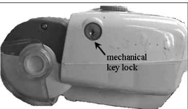
After the filled syringe is inserted into the syringe pump, the plunger carriage must be locked. Instead of using a mechanical key as shown in Figure 1.1, this project implements the keyless entry monitoring system by using secure password to lock and unlock the slot plunger for provision against accidental modification of settings and to prevent syringe theft or unauthorized replacement of syringe.
Figure 1.1: Ordinary Mechanical Key Lock Of PCA Syringe Pump Source: By courtesy of Hospital Sultanah Aminah, Johor, Malaysia
3 Thus, another objective of this project is to produce an efficient security system in which USB feature is build in the Secure Entry Monitoring main board. With the peripheral connected, the data captured in Secure Entry Monitoring main board can be transferred to computer easily for further data analysis and investigation. In other words, data can be stored in the main board, USB flash drive and computer.
In fact, most of the existing PCA syringe pumps are already equipped with the LCD display and buttons/keypad (buttons arranged in matrix form), as shown in the literature review in section 2.1 in Chapter II. Therefore, minimum cost is needed to upgrade the existing product to implement the project’s objectives because this project is making use of the of the features available (LCD display and buttons/ keypad).
1.3 PROJECT SCOPE
Since security systems are growing ever more popular, various kinds of security systems are available in diverse applications such as residential, business and working area. In this project, the Secure Entry Monitoring System (SEMS) will contribute to not only the business and working field, but also to the medical line. In the former area, this secure monitoring system can be implemented in houses, offices and banks. For the latter, PCA syringe pump is one of the suitable applications.
This project involves hardware, firmware and software. There are seven major parts for programming, as shown below:
1. LCD display
2. Real Time Clock and Calendar 3. Hex keypad