A Numerical Analysis on Double Acting Pneumatic Telescopic
Cylinder Motion Characteristics
1Abdul Talib Din (Author)
1Faculty of Mechanical Engineering,
Universiti Teknikal Malaysia Melaka, UTeM, Melaka, Malaysia
e-mail : [email protected]
Abstract - This paper presents the design and development of a mathematical model of dynamic motion of pneumatic telescopic cylinder. The aim of the research is to develop a telescopic pneumatic system that can handle variable load at constant forward and retracting speed. The design analysis carried out is focused and based mainly on identifying the characteristics of the pneumatic cylinder using force-feedback control system. A conceptual model was made and the limitations were identified and further studied on nonlinear behavior and the solutions to improve its characteristics were sought in the process of designing and developing the telescopic cylinder. The control system contained combination of proportional and on-off valve in controlling the telescopic cylinder movement. The determination of the displacement of each stage of the telescopic cylinder, velocity and acceleration were optimized using multi-order PI controller. Method of research is performed by simulation studies using Matlab Simulink to prove the dynamic mathematical modeling of the cylinder. During the last stage of the research, a scale down model of the telescopic cylinder was fabricated incorporating all design aspects derived from the theoretical and simulation analysis. After that an experimental study was conducted on the scale down cylinder in order to validate the data obtained. The validated data shall be used in the design of the full scale of the telescopic cylinder. It is found that from the numerical analysis, the designed system can achieve a constant speed although loaded with varied axial force.
Keywords - telescopic cylinder; motion characteristic ; force-feedback ; pneumatic
I. INTRODUCTION
Telescopic is design and applied in hydraulic or pneumatic cylinders in order to minimize the length of the stroke when in retracted position. It can be found in several applications such as telescoping fluid actuator that useful in industries for localized applications of considerable forces in areas that lack sufficient space, in agricultural tools or on vehicle for use in construction and maintenance work on overhead system as the telescopic cylinder were mounted on the platform and can be lifted enough to reach the uppermost parts of the structure [10],[11].
2Roslina Aida Rahimi (Co-author)
2Faculty of Mechanical Engineering,
Universiti Teknikal Malaysia Melaka, UTeM, construction that minimize the production cost on material construction and maintenance while at the same time reducing the overall length of the pneumatic cylinder when retracted and to maximize the effective length when extended. [9]
Pneumatic cylinder is one of most common type of industry actuators. Compared to conventional electric and hydraulic actuators, it offers better alternative in certain types of applications. Pneumatic actuators provide the enumerated qualities at low cost and suitable for clean environments as it safer and easier to work with [1], [2]. Furthermore, the pneumatic actuator has a lower specific weight and a higher power rate (torque-squared to inertia ratio) than an equivalent electromechanical actuator. In some cases, a pneumatic system may provide a significant weight advantage [4].
AEROSPACE ENGINEERING (CMAE 2010), CHENGDU, CHINA
and controlled using force-feedback of system thatwill also control the nonlinearities obtained from the compressibility of air. The behavior of the actuator is then controlled by multi order Proportional-Integral (PI) that will control the error in displacement, velocity and acceleration of the cylinder motion. Simulation results were presented to obtain the idea of the telescopic cylinder behavior.
II. TELESCOPIC CYLINDER
MODEL
Telescopic pneumatic cylinder consists of several segments of cylinder which could shorten and lengthen by mean of tightly slide-on hollow cylindrical shape high pressure containers as shown in Figure 1 below.
Figure 1. Pneumatic Telescopic cylinder. (source : Vatel. B,1994)
The cylinder was designed by providing a telescopic cylinder having several stages with each having a hollow piston and piston rod opening toward an inlet end of the cylinder and substantially contained therein when retracted. An inner sealed bushing on the opposite end of the piston rod is used as a cylinder face cap. Air opening serving as exhaust ports are aligned to vent the voids between piston rods when sequentially extending the several stages. [9]
III. PNEUMATIC ACTUATOR MODEL
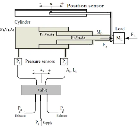
The pneumatic system that is used in this research consists of double acting telescopic cylinder that reacts as force in its motion and connected to the valve. In this study, a combination of 5/3 way valve and proportional regulator has been applied. The combination of the on-off valve and pressure regulator is needed in controlling the speed of each stage and at the same time to avoid shock when the telescopic cylinder retract or extend from stage to stage. The schematic figure can be seen in figure 2.
Figure 2. Schematic representation of the pneumatic telescopic cylinder-valve system.
The mathematical model considers the dynamics of the piston and pressure of the chamber in extended and retracted motion. The system model consist of several equations as follows [1],[2]
:-Mx¨+Bx˙+Ff+F=A(P1−P2) (1)
˙
P1= CfR√T A
(
12L+x
)
[αin¯Aυ1inPsm˙r(Ps,¯P1)
−αex¯Aυ1exP1m˙r(P1,¯Pa)]−α P1A
A(1
2L+x)
˙ x
˙
The control structure of the pneumatic telescopic cylinder can be seen in figure 3. It is aim to obtain the same velocity value for extended movement of each stage of the telescopic cylinder. The telescopic cylinder used in this experiment consists of three stages with different value of surface area. Proportional-Integral-Derivative (PID) was applied in this study to control the error measurement from the pneumatic system [3]. However the measurement of the multi-order value of displacement, velocity and acceleration of this study were only using Proportional-Integral and usually be called PI controller. There were several studies on control strategies such as (Jihong et al., 1999) that using combination of modified PID controller to a pusher mechanism in the packaging of confectionary products that give accurate positioning and time accuracy [5]. In other cases, PID control shown good control level of speed for radial piston air motor and both speed and direction control of motor is feasible in real time (Takhi et al., 2001).
Figure 3. Control structure of Pneumatic Telescopic Cylinder Motion
B. Inner Loop Control
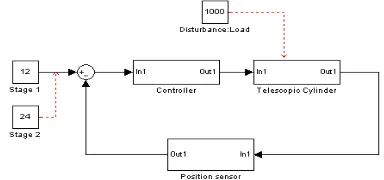
The inner loop control was simulated using PI controller whereby the proportional makes change to the output that is proportional to the current error value while integral function was to reset magnitude and the duration of the error by summing the instantaneous error over time. The inner loop schematic can be seen in figure 4.
Figure 4 . Position feedback varied with load disturbance
The optimum value of the Multi-order Proportional-Integral (PI) controller employed in this paper is adopted [8]. The optimum value of the real time desired force for the pneumatic actuator is given by
AEROSPACE ENGINEERING (CMAE 2010), CHENGDU, CHINA
Single order of PI controller namely known aszero-order PI controller, first-order PI controller, and the second-order PI controller. The optimum value of the real time desired force for the pneumatic actuators given by the zero-order PI, first-order PI, and second-order PI controller given in Eq. (6), (7), and (8).
∑
F=ez[
KP+KIs
]
z (6)∑
F=e˙z[
KP+KIs
]
˙z (7)
∑
F=e¨z[
KP+KI
s
]
¨z (8)(8)
Where
Pout : Proportional term of output
Kp : proportional gain, a tuning parameter
Ki : Integral gain, a tuning parameter
e : Error = SP-PV
t : Time or instantaneous time(the present)
V. SIMULATION RESULTS
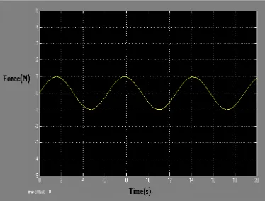
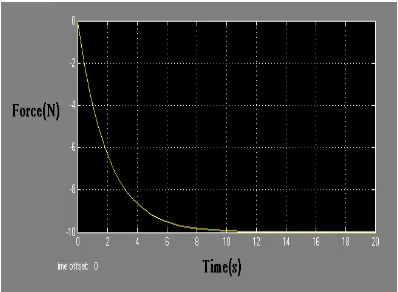
Figure 5 and 6 show the simulation results of the telescopic cylinder movement using certain given load.
Simulation of the multi order velocity and acceleration were obtained using Simulink and compared with the theoretical calculation. Graphs shown are the results of the actual condition while the theoretical calculation represents the desired value of the zero, first and second order for the telescopic movement.
Figure 5a. Velocity at 5 kg in sinusoidal line
Figure 6a. Acceleration at load 5 kg in sinusoidal line
Figure 6b. Acceleration at load 5 kg in quadratic line
VI. CONCLUSION
The differential value of displacement, velocity and acceleration has been developed by minimizing the error from the position and force feedback control structure. The simulation results shown that the telescopic cylinder system able to achieve desired performance of the pneumatic actuator compared to the theoretical calculation that has been made. In conclusion, the simulation results manage to obtain good agreement with the expected experimental value where the motion of each telescopic stage moving in constant velocity even though the surface area is different from each telescopic stage. Besides that, the cylinder able to
reduce jerk condition in motion changing stage to stage that proves the functionality of on-off and proportional regulator valve combination.
VII. REFERENCES
[1] Richer, E. and Hurmuzlu, Y. , A high performance pneumatic force actuator system Part I - Nonlinear mathematical model. Journal of Dynamic Systems, Measurement and Control, ASME, Vol.122, No.3, 2000, pp 416–425.
[2] Richer, E. and Hurmuzlu, Y., A high performance pneumatic force actuator system Part II – Nonlinear controller design. Journal of Dynamic Systems, Measurement and Control, ASME, Vol.122, No.3, 2000 , pp 426–434.
[3] Lai, J.Y., Menq, C.H. and Singh, R., Accurate Position Control of a Pneumatic Actuator,
Journal of Dynamic Systems, Measurement and Control, ASME, Vol.112, No.4, 1990, pp 734-739.
[4] Hazem I. Ali, Mohd Noor, S.B., S. M. Bashi, M. H. Marhaban , A Review of Pneumatic Actuators (Modeling and Control), Australian Journal of Basic and Applied Sciences, Vol 3(2), 2009, pp 440-454.
[5] Xiang, F., Block Oriented Nonlinear Control of Pneumatic Actuator Systems, PhD thesis, Royal Institute of Technology, KTH. , 2001
[6] Kamman, J. W. and Jennings, A. System Identification and Control of a Pneumatic Cylinder. Western Michigan University.Technical Report Number: MAE-05-07. 2005
[7] Wang, J., Kotta, U. and Ke, J., Tracking control of nonlinear pneumatic actuator systems using Static state feedback linearization of the input–output map . Proc. Estonian Acad. Sci. Phys. Math., Vol 56, 1, 2007, pp 47–66.
[8] Imaduddin, F., Hudha, K., Ubaidillah and Jamaluddin , H., Simulation and Experimental Evaluation of Multi-order Proportional-Integral Control for Pneumatically Actuated Active Suspension System. 2008, Universiti Teknikal Malaysia Melaka.
[9] Vatel, B. Pneumatic Telescoping Cylinder and Method. US005341724A(Patent). 1994
[10] Franco Telescopic Extensible Rod., 0666019A1(Patent). 1994