i
“ I hereby declare that I have read through this report entitle “Data Acquisition System for air conditioning system in FKE for analysis” and found that it has comply the fulfillment for awarding the degree of Bachelor of Electrical Engineering (Mechatronic)”
Signature :………
Supervisor’s Name :Mr. Zamani Bin Md. Sani
ii
DATA ACQUISITION SYSTEM FOR AIR-COND IN FKE FOR ANALYSIS
LOH WUI FOON
A report submitted in fulfillment of the requirement for the degree of Mechatronic
Faculty of Electrical Engineering
University Technical Malaysia Malacca
iii
I declare that this report entitle “Data Acquisition System for air conditioning System in FKE for analysis” is the result of my own research except as cited in the references. The report has not been accepted for any degree and is not concurrently submitted in
candidature of any other degree.
Signature :
………
Name : LOH WUI FOON
iv
v
Table of Contents
Chapter 1 Introduction ... 1
1.1 Project Overview ... 1
1.2 Project Objective ... 2
1.3 Project Scope ... 2
1.4 Problem Statement ... 3
Chapter 2 Literature Review... 4
2.1 Introduction ... 4
2.2 Literature Review ... 4
2.2.1 Portable DAQ... 5
2.2.2 Design of DAQ ... 6
2.2.3 Review of Design DAQ ... 13
2.3 Theory ... 14
2.3.1 Standard Room Temperature ... 14
2.3.2 Air Flow System ... 14
2.3.3 Refrigeration Cycle ... 18
2.3.4 Air-Conditioning Control System ... 22
2.3.5 Air Flow Structure ... 24
2.3.6 Hardware ... 25
2.3.7 Software ... 29
Chapter 3 Methodology ... 31
3.1 Introduction ... 31
vi
3.2.1 Designing Electronics Circuit ... 33
3.2.2 Design Prototype Housing ... 34
3.2.3 Integration of Both Designs ... 34
3.3 Hardware Implementation ... 35
3.3.1 PIC Microcontroller ... 35
3.3.2 RTC and SD-Card ... 37
3.3.3 Liquid Crystal Display (LCD) ... 38
3.4 Software Implement ... 38
3.4.1 MikroC Programming Algorithms ... 39
3.4.2 SolidWorks ... 40
3.5 Design of Experiments ... 40
3.5.1 Experiment 1: Determine the accuracy of detected temperature value in closed room... 41
3.5.2 Experiment 2: Functionality test for SD-Card data storage ... 42
3.6 Improvement for Air-conditional System ... 43
3.6.1 Target of Improvement ... 43
3.6.2 Improvement with BMS ... 44
3.6.3 Improvement with Manual Control Valve ... 45
3.6.4 Second Improvement with Manual Control Valve ... 46
Chapter 4 Results and Analysis ... 47
4.1 Introduction ... 47
4.2 Hardware Result ... 47
4.2.1 Circuit ... 48
4.2.2 Prototype Housing ... 49
vii
4.3.1 Simulation Result ... 51
4.4 Experiment Results and Analysis ... 52
4.4.1 Experiment 1: Determine the accuracy of detected temperature value in closed room... 52
4.4.2 Experiment 2: Functionality test for SD-Card data storage ... 55
4.5 Results and Analysis for Actions of Improvement ... 56
4.5.1 Normal Setting (before improvement) ... 56
4.5.2 Improvement with BMS ... 58
4.5.3 Improvement with Manual Control Valve ... 59
4.5.4 Second Improvement with Manual Control Valve ... 60
4.5.5 Combination View for Graph of Improvement ... 61
Chapter 5 Discussion of Result ... 62
5.1 Discussion ... 62
5.2 Problems ... 63
5.2.1 Hardware Problem ... 64
5.2.2 Software Problem... 64
Chapter 6 Conclusion and Recommendation ... 65
6.1 Conclusion ... 65
viii
Table of Figures
Figure 2-1 System Hardware Structure for PV DAQ ... 6
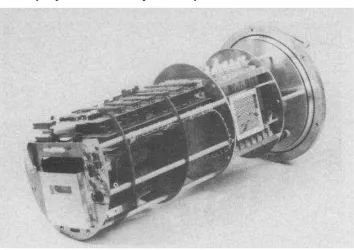
Figure 2-2 Battery-Operated DAS ... 7
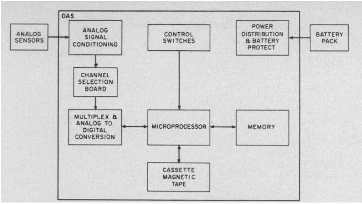
Figure 2-3 Block diagram for Battery-Operated DAS ... 8
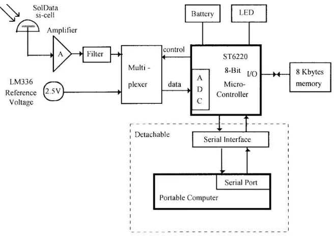
Figure 2-4 Block Diagram for Mukaro’s DAS ... 9
Figure 2-5 DAQ setup configuration ... 10
Figure 2-6 System Chart for Temperature and Humidity DAQ ... 11
Figure 2-7 AHU system ... 15
Figure 2-8 FCU system ... 15
Figure 2-9 Connection between AHU system to room ... 16
Figure 2-10 AHU room in FKE Building ... 16
Figure 2-11 Control Valves on Pipes ... 17
Figure 2-12 AC-Refrigerator Cycle ... 18
Figure 2-13 Air-Conditional System ... 18
Figure 2-14 Compressor for Air Conditional System ... 19
Figure 2-15 Condenser for Air Conditional System ... 19
Figure 2-16 Evaporator for Air-Conditioning system ... 20
Figure 2-17 State of Working Fluid ... 21
Figure 2-18 Example for BMS control System ... 22
Figure 2-19 Manual Control System... 23
Figure 2-20 Structure of Level 3 wing A, FKE ... 24
Figure 2-21 DS1307 ... 26
ix
Figure 2-23 Micro SD-Card with Adapter ... 28
Figure 3-1 Flow Diagram for Manufacturing of portable DAQ ... 32
Figure 3-2 Integration of Circuit Board ... 33
Figure 3-3 PIC18F452 ... 36
Figure 3-4 Liquid Crystal Display (LCD) ... 38
Figure 3-5 Programming Algorithms... 39
Figure 3-6 Location of data recording ... 43
Figure 3-7 Setpoint in BMS ... 44
Figure 3-8 Manual Valve Control ... 45
Figure 4-1 Complete Basic Circuit ... 48
Figure 4-2 Design of Prototype Housing ... 49
Figure 4-3 Dissemble Mode... 50
Figure 4-4 Real design of Housing ... 50
Figure 4-5 Comparison between DAQ and Logger ... 53
Figure 4-6 Temperature data collected from portable DAQ ... 54
Figure 4-7 Temperature data collected from standard Logger ... 54
Figure 4-8 Experimental results for SD-Card test ... 55
Figure 4-9 Temperature Output before Improvement ... 56
Figure 4-10 Temperature during Day Time ... 57
Figure 4-11 Temperature Output for Improvement with BMS ... 58
Figure 4-12 Temperature Output for Improvement with Manual Control Valve ... 59
x
List of Tables
Table 2-1 Comparison between DAQ... 12
Table 2-2 Pin Layout of SD-Card for SD and SPI mode ... 28
Table 3-1 Feature of PIC18F452 ... 35
Table 4-1 Comparison between DAQ and Temperature Logger ... 52
List of Equations Equation 4-1 Percentage error ... 41
xi
Projek Abstrak
xii
xiii
Project Abstract
xiv
1
Chapter 1 Introduction
1.1 Project Overview
2
1.2 Project Objective
To develop an equipment with the ability to record the temperature changes in a room for 3 days time by using the circuit integrated with temperature sensor (LM035), microcontroller PIC 18F452, Real Time Clock (DS1307) and SD-Card. To find out the source of problem for the unstable temperature output in the
building.
To analyze the collected information base on the setting adjustment to achieve the optimum room temperature.
To collect the data of measured temperature for problem analysis.
1.3 Project Scope
3
1.4 Problem Statement
4
Chapter 2 Literature Review
2.1 Introduction
This chapter will explains the source of idea for design, concept, specification and other information that related to the project. This information is obtained from the researches on the portable data acquisition system. The information is divided to two parts; first part is refers to the available DAQ in the market, these information will help to develop and improve the new design DAQ through the project; the other part stand of the survey on the components to used, which components can be improved or removed from the previous DAQ. Besides, all the theories of all components and compatible software that are used in this project will also be discussed in this chapter.
2.2 Literature Review
5
2.2.1 Portable DAQ
Data Acquisition System (DAQ/DAS) is a device or equipment that uses to measure and record the real world physical conditions. For portable DAQ, the basic function is still maintained, and this equipment had been improved with the feature of mobility, an external battery source is used to replace the power supply for the whole circuit. However, there is limitation for the usage of power in battery, improvement in duration of usage is needed by consider the power consumption for every device included in the main circuit.
DAQ usually consists of multiple components such as microcontroller/microprocessor, multiplexer, sensors, RTC, LCD, and external memory. Microcontroller in DAQ acts like a brain where it controls the whole system and I/O peripherals. These components are connected to the main controller via bus connection.
The capacity of DAQ is depends on the memory used in the design. There are plenty lot of memory types in the market, memory selection is based on the amount of data stored. The data collected will be temporarily stored into the memory of DAQ, it will then transferred to computer by using the communication bus such as serial bus, parallel bus, USB bus, or SD-card etc..
6
2.2.2 Design of DAQ
2.2.2.1 PV power station remote monitoring system data acquisition device
J.M.Xiao and the group were developed a data acquisition system to monitor and control the photovoltaic system. For the past, this system is generally needed to continuously monitoring the data shown in equipment. Therefore, a large part of the current constructions of photovoltaic power station are in the environment that is failed for long-term duty. In this design, telephone lines and RS-232 bus is use to transfer data, with the existing telephone network, remote monitoring application has replace the staff on duty in PV power station. At the same time, the man-power resources in this station are greatly reduced. The DAQ is use to monitoring the DC current, AV voltage, temperature testing, parameter collecting, real-time monitoring, remote monitoring and finally storing all the data in the PV power station. (J.M.Xiao, 2011) [1]
7
2.2.2.2 Battery-Operated Data Acquisition System
Figure 2-2 Battery-Operated DAS
8
9
2.2.2.3 Microcontroller-based Data Acquisition System for Solar Radiation
R.Mukaro, had invented a low-cost battery operated microcontroller-based data acquisition system to overcome the difficulty to collect the quantitative information on global solar radiation and other environmental parameters as research material. This equipment is used to monitor the solar radiation continuously and the improvement for this system is regardless of hardware changes. The device communication between the device and computer is through RS-232 serial link, recorder data is transferred to computer for subsequent analysis. The main controller used in this equipment is STT62E20 microcontroller which is driven by 8MHz crystal oscillator. The data collected is stored in a serial EEPROM before uploaded to computer. The schematic for this design is simple and run in offline mode to reduce the cost consumption and get rid of network problems. (Mukaro, 1999) [3]
10
2.2.2.4 Data Acquisition System for Capturing Dynamic Transient in Control
Valve
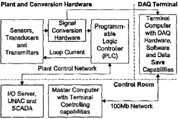
There are also DAQ developed to predict for the effect or behavior of a system. A.Helling had constructed a mathematical function in his DAQ to capture the dynamic transients in a control valve. The dynamic mathematical model will be used in a simulator to predict the behavior of the device. Neural Networks (NN) and fuzzy logic systems (FLS) are included in this modeling. This DAQ is integrated with sensors, transducers, transmitters, process hardware and some software for data management. There are two construction methods for this system, which is internal DAQ card and external DAQ card. For external DAQ, the device is communicating through parallel port and Universal Serial Bus (USB) ports. In additional, the loop current is converted to voltage by determined the value of sense resistor. The loop receivers have an internal conversion accuracy of 0.1% and operation temperature up to 70 degree Celsius. This is an ideal device to be installed in System Control and Data Acquisition (SCADA) and Resistor Temperature Devices (RTC). (Armold Helling, 2004) [4]