i
AUTOMATION PROCESS BY USING PLC OMRON WITH PC CUSTOMIZED SIMULATOR
Teh Tze Keong
ii
“ I hereby declare that I have read through this report entitle “Automation Process by Using PLC OMRON with PC Customized Simulator” and found that it has comply the partial fulfillment for awarding the degree of Bachelor of Mechatronic Engineering”.
Signature : ...
Supervisor‟s Name : EN. SHAHRUDIN BIN ZAKARIA
iii
AUTOMATION PROCESS BY USING PLC OMRON WITH PC CUSTOMIZED SIMULATOR
TEH TZE KEONG
A report submitted in partial fulfillment of the requirements for the degree of Bachelor of Mechatronics Engineering
Faculty of Electrical Engineering
UNIVERSITI TEKNIKAL MALAYSIA MELAKA
iv
I declare that this report entitle “Automation Process by Using PLC OMRON with PC Customized Simulator” is the result of my own research except as cited in the references.
The report has not been accepted for any degree and is not concurrently submitted in candidature of any other degree.
Signature : ...
Name : TEH TZE KEONG
v
ACKNOWLEDGEMENT
First and foremost, I would like to express my greatest gratefulness and sincere thanks to my supervisor, Mr. Shahrudin Bin Zakaria, for his valuable helps and guidance in the portion of supervision of this final year project. In truth, he gave me precious advices during my dilemma in doing this final year project through this period of time.
In addition, I would like to thanks Sophic Automation Sdn. Bhd. PLC senior programmer, Tan Khaik Koon, without him, I would not be able to get an overall idea on how pass data to data memory, he had offer me a great help in this final year project.
Furthermore, I would like to give my appreciation to Sophic Automation Sdn. Bhd. Software senior programmer, Yeoh Yow Yih for teaching me in Microsoft Visual Basic 2008 programming. Without his support and patient, I would not be able to write coding in Visual Basic in such short period.
Last but not least, the appreciation gives to the lab technician, Siti Fatimah Binti Kamarudin, due to her cooperation by letting me to make use of PLC in PLC laboratory. Without her, I would not be able to access OMRON PLC CQM1H-CPU21 in PLC laboratory. My fellow friends should be also recognized for their support, my sincere appreciation to those who had provided me brilliant idea and assistance during my final year project. Unfortunately, it is impossible to list all of my friends in this restricted space. I am thankful to my family members.
vi
ABSTRACT
vii
ABSTRAK
viii
TABLE OF CONTENTS
DECLARATION………...iii
ACKNOWLEDGEMENT ... v
ABSTRACT ... vi
ABSTRAK ...vii
TABLE OF CONTENTS ... viii
LISTS OF TABLES ... x
LIST OF FIGURES ... xi
LIST OF ABBREVIATIONS ...xii
CHAPTER I INTRODUCTION ... 1
1.1 Introduction ... 1
1.2 Problem Statement ... 3
1.3 Objectives ... 3
1.4 Project Scope ... 4
CHAPTER 2 LITERATURE REVIEW ... 5
2.1 Introduction ... 5
2.2 Types of Interface... 6
2.3 Types of Connection ... 8
2.4 Type of header ... 9
2.5 Software Tools ... 11
2.5 Literature Review Summary ... 14
CHAPTER 3 METHODOLOGY ... 15
ix
3.2 Software Design ... 17
3.4 Gantt Chart ... 19
3.5 K-chart ... 19
3.6 Study and Research ... 22
CHAPTER 4 RESULT AND ANALYSIS...24_Toc326875988 4.1 CQM1H-CPU21 Graphical User Interface (GUI) Data Read Accuracy... 24
4.2 CQM1H-CPU21 Graphical User Interface (GUI) Data Read Stability ... 28
4.3 Hardware Repeatability ... 30
4.4 Industrial Survey ... 32
CHAPTER 5 DISCUSSION ... 34
CHAPTER 6 CONCLUSION AND RECOMMENDATION ... 37
6.1 Conclusion ... 37
6.2 Recommendation... 38
REFERENCES ... 39
x
LISTS OF TABLES
Table 2.1: Touch Screen VS Laptop/Desktop ... 7
Table 2.2: Comparison of Types of Connections ... 9
Table 2.3: Comparison of Header Code for Read Purpose ... 10
Table 2.4: Command Line Interface VS Graphical User Interface ... 11
Table 3.1: Gantt Chart ... 20
Table 3.2: Definition of Accuracy ... 27
Table 4.1: Definition of accuracy ... Error! Bookmark not defined.7 Table 4.2: Actuator trigger according to length of wood ... 300
xi
LIST OF FIGURES
Figure 3.1: Overall Project Flow Chart ... 16
Figure 3.2: Software Design Flow Chart ... 18
Figure 3.3: K-Chart ... 21
Figure 3.4: Command and Response Format ... 22
Figure 4.1: CQM1H-CPU21 Graphical User Interface ... 25
Figure 4.2: CQM1H-CPU21 Graphical User Interface after Connection Establish ... 26
Figure 4.3: Graph of Accuracy versus Number of Experiment ... 27
Figure 4.4: Graph of Connection Stability versus Time ... 29
Figure 4.5: Hardware outlook ... 30
Figure 4.6: Success/Fail versus length of material ... 31
xii
LIST OF ABBREVIATIONS
PLC - Programmable Logical Controller I/O - Input or output
LED - Light emitting Diode PC - Personal Computer
API - Application Programming Interface GUI - Graphical User Interface
1
CHAPTER I
INTRODUCTION
This chapter explains the traditional Programmable Logical Controller (PLC) status monitoring system compared with the proposal system.
1.1 Introduction
Programmable Logical Controller (PLC) is one of the famous automation process controller used all over the world. It is mainly apply in control of machinery on factory assembly line, quality control line or light fixtures for more economy operational cost. Programmable Logical Controller (PLC) is famous because of its flexibility and user friendly ladder diagram programming language.
2
By the way, Programmable Logical Controller (PLC) is not as perfect as we think, it is good at flexibility for automation process control and other applications, but, the monitoring of it is limited to those people who know how to use and program the Programmable Logical Controller only. In order to monitor how much data or the counter‟s value, the user will need to enter the Programmable Logical Controller (PLC) ladder diagram to view the data they need. In addition, every different kind of Programmable Logical Controller got their own custom ladder diagram programming language, although the flow to program is almost the same, the end user still unable to learn every kind of language for it except for those expertises.
From the above paragraph, it is clear that if want to know the status or data of automation process, will need to hire someone who able to access and read Programmable Logical Controller (PLC) ladder diagram just to obtain the data we want from Programmable Logical Controller (PLC), and this phenomena is really waste of human resources. Thus, the implementation of PC base simulator is require to show the data of Programmable Logical Controller (PLC) on the screen of PC without need any access into the Programmable Logical Controller (PLC).
3
1.2 Problem Statement
From the internship period, I had observe that a lot of factories engineer or technician still do not have any idea on their device status such as sensor, actuator, motor and sort of automation devices. This had make hard for engineer or technician who going to run maintenance and also in the process of monitoring machine status such as the motor status, or the output counts; this is because not everyone know how to monitor the status of Programmable Logical Controller (PLC) ladder diagram, or directly from the LED indicator on the Programmable Logical Controller (PLC). From this project, the low cost monitoring system will be developed and able to reduce operation cost of the factory for long term planning and able to prevent put engineer or technician into great danger while operate or running maintenance on the machine.
1.3 Objectives
The objectives of this project are:
i) To design a PC simulator that able to monitor the Omron CQM1H-CPU21 PLC current I/O status.
ii) To apply the knowledge of Microsoft Visual Basic 2008 Programming in automation monitoring process that controlled by Omron CQM1H-CPU21 PLC. iii) To design and develop a low cost PC simulator that able to monitor the Omron
CQM1H-CPU21 PLC current I/O status.
4
1.4 Project Scope
This project will focus primarily on the software design (types of programming language) and hardware design to monitor the Omron CQM1H-CPU21 PLC I/O status directly on the screen of PC via PC simulator that designed by Microsoft Visual Basic 2008.
a) Software part:
1. To program a PC simulator by using Microsoft Visual Basic 2008.
2. To read I/O status from Omron CQM1H-CPU21 PLC only, not include write data into PLC.
3. The PC simulator only can be used with Omron CQM1H-CPU21 PLC only. 4. The PC simulator must connect to Omron CQM1H-CPU21 PLC by using
RS232 cable.
b) Hardware Part
1. The automation process to be designed possesses not more than 10 I/O on Omron CQM1H-CPU21 PLC.
2. The PC which equip with PC simulator must be connected to PC by using RS232 cable and the wiring connection must be refer to Omron CQM1H-CPU21 Operational Manual.
5
CHAPTER 2
LITERATURE REVIEW
2.1 Introduction
PC simulator is one of the methods to connect the Programmable Logical Connector (PLC) and monitor the Programmable Logical Controller (PLC) status. This type of application is fairy important and possess high demand in the industry area, especially for those do not have knowledge on Programmable Logical Controller (PLC). As we know that, the Inputs and outputs of Programmable Logical Controller (PLC) are form by various kinds of dangerous equipments, such as motor, actuator, driller, sensor, even 240V electric supply is count as input.
Thus, with this system, it can prevent that some engineers or technicians who not equip with Programmable Logical Controller being injured or hurt by the inputs or outputs of Programmable Logical controller (PLC) while they are going to run a maintenance on the machine. In addition, with this project, it is able to reduce the production operation cost monthly by reduce the human resources needed in that particular area.
6
2.2 Types of Interface
There are many methods to illustrate the data of Programmable Logical Controller (PLC) to user through pre-determine interface path. The available interfaces are monitor screen of laptop or desktop and touch screen.
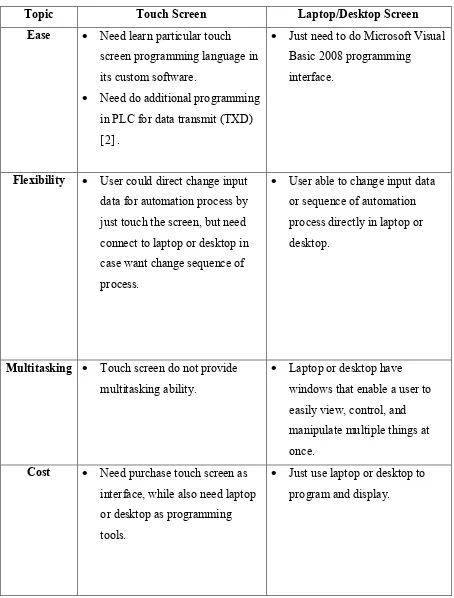
Among these two types of screen, the price of touch screen will be higher compare to monitor screen of laptop or desktop. In addition, user need to purchase additional touch screen in order to use it as interface, but the user still need a laptop or desktop to program it. Furthermore, touch screen size normally is smaller than laptop or desktop monitor screen. In order to be able using touch screen as interface, the user need to learn the way to program and design the touch screen interface[1], while if just use laptop or desktop screen, user just need to learn Microsoft Visual Basic 2008 language. For touch screen, user can just change the input data on the screen by touching it, but if want to change the sequences of automation process, a laptop or desktop still needed, whereby if using the screen of laptop or desktop as interface, both sequence and input data change can be done easily in the laptop or desktop.
In addition, the ladder diagram in CQM1H-CPU21 PLC is different for touch screen interface and normal interface created by Microsoft Visual Basic 2008. This is because touch screen is only used to display, while, means in the PLC ladder diagram, need to set program, that is transmit (TXD), so that the PLC will send the data from PLC to touch screen automatically [2] . Whereby, the simulator created by the Microsoft Visual Basic 2008 will just use data read function to read the value or data in normal ladder diagram.
7
Table 2.1: Touch Screen VS Laptop/Desktop
Topic Touch Screen Laptop/Desktop Screen
Ease Need learn particular touch screen programming language in its custom software.
Need do additional programming in PLC for data transmit (TXD) [2] .
Just need to do Microsoft Visual Basic 2008 programming
interface.
Flexibility User could direct change input data for automation process by just touch the screen, but need connect to laptop or desktop in case want change sequence of process.
User able to change input data or sequence of automation process directly in laptop or desktop.
Multitasking Touch screen do not provide multitasking ability.
Laptop or desktop have windows that enable a user to easily view, control, and manipulate multiple things at once.
Cost Need purchase touch screen as interface, while also need laptop or desktop as programming tools.
8
2.3 Types of Connection
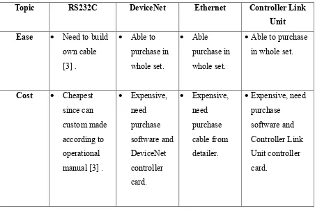
There are few types of connection available for the CQM1H-CPU21 Programmable Logical Controller; they are host link connection which using RS232C cable, DeviceNet, Controller Link, and Ethernet.
Among these four types of connection, RS232C provide lowest budget option, followed by Ehternet, DeviceNet and Controller Link. This is because we can just simply purchase the RS232C connector, also known as 9 pin D-sub connector and make own cable by following the OMRON operational manual under wiring section [3-5] . The function of RS232C connection is almost the same compare with Ethernet, DeviceNet, and Controller Link connection.
From the data transmit aspect, DeviceNet and Controller Link connection possesses better solution, this is because they no need any additional program in order to show their data on the screen. This can be done by just purchase DeviceNet cable and Controller Link unit with installed software, and then the data can be seen without any extra interface needed. Method to operate the DeviceNet can be obtain in its manual[6] .Whereby, Controller Link Unit is another additional plug in for CQM1H-CPU21 Programmable Logical Controller, this Controller Link Unit are used to transmit data in big quantity, but it still need an software interface created by user [7] . For Ethernet connection, it can conduct function as excellent as Control Link Unit, but we need to purchase OMRON FINS Ethernet Communication Interface API, the price of this will cost $395.00 (U.S. Dollar) [8] . And this is over my range of budget for this project.
9
Table 2.2: Comparison of Types of Connections
Topic RS232C DeviceNet Ethernet Controller Link
Unit Ease Need to build
own cable [3] .
Able to purchase in whole set.
Able purchase in whole set.
Able to purchase in whole set.
Cost Cheapest since can custom made according to operational manual [3] .
Expensive, need purchase software and DeviceNet controller card. Expensive, need purchase cable from detailer.
Expensive, need purchase
software and Controller Link Unit controller card.
2.4 Type of header
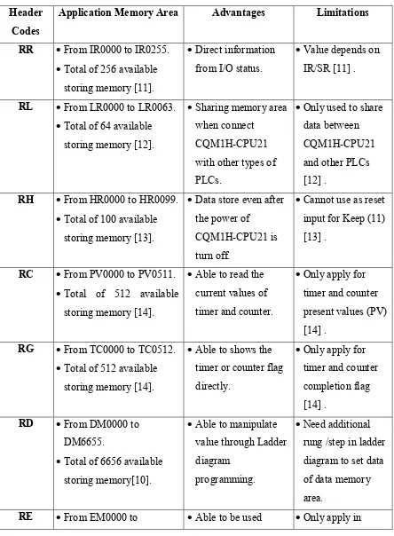
In the CQM1H-CPU21 Programmable Logical Controller, there are total 38 type of header code. But in this project only use 1 type of header code in this project to read the data from the CQM1H-CPU21 Programmable Logical Controller.
10
IR243 and from SR244 to SR251. Table 2.3 shows the comparison between these 8 types of header codes, and their application field [9]:
Table 2.3: Comparison of Header Code for Read Purpose Header
Codes
Application Memory Area Advantages Limitations
RR From IR0000 to IR0255. Total of 256 available
storing memory [11].
Direct information from I/O status.
Value depends on IR/SR [11] .
RL From LR0000 to LR0063. Total of 64 available
storing memory [12].
Sharing memory area when connect
CQM1H-CPU21 with other types of PLCs.
Only used to share data between CQM1H-CPU21 and other PLCs [12] .
RH From HR0000 to HR0099. Total of 100 available
storing memory [13].
Data store even after the power of
CQM1H-CPU21 is turn off.
Cannot use as reset input for Keep (11) [13] .
RC From PV0000 to PV0511. Total of 512 available
storing memory [14].
Able to read the current values of timer and counter.
Only apply for timer and counter present values (PV) [14] .
RG From TC0000 to TC0512. Total of 512 available
storing memory [14].
Able to shows the timer or counter flag directly.
Only apply for timer and counter completion flag [14] .
RD From DM0000 to DM6655.
Total of 6656 available storing memory[10].
Able to manipulate value through Ladder diagram
programming.
Need additional rung /step in ladder diagram to set data of data memory area.
11
EM6143.
Total of 6144 available storing memory [15].
freely. CQM1H-CPU61
[15] .
Not available in CQM1H-CPU21 PLC.
RJ From AR0000 to AR0027. Total of 28 available
storing memory[16].
Serve as CQM1H-CPU21 PLC internal setting memory area.
Only used for setting purpose.
2.5 Software Tools
Software tool is one of the most powerful PC based path to design whatever applications we want. There are some common in use software tools such as Microsoft Visual studio, MATLAB, C Sharp, Perl and so on. Software tools are mainly divided into 2 main types that are Command Line Interface software and Graphical User Interface. Both kinds of interfacing software got their own strength, but also got their shortage when compare to each other. Comparison of Command Line Interface (CLI) with Graphical User Interface (GUI) can be seen as in the Table 2.4 below [17, 18] :
Table 2.4: Command Line Interface VS Graphical User Interface
Topic Command Line Interface (CLI) Graphical User Interface (GUI) Ease Need to get familiar and
memorized in order to operate the command.
Difficult for beginner to navigate and operate a command line interface.
Fast tools for expertise.
May have some difficulties for beginner to learn.
Control technique includes using of mouse to control. Easier to pick up this interface
compare to Command Line Interface
12
file system, for example, they could move a file just by 1 line command.
specify tasks may need to resort to a command line to complete a particular task.
Appearance The appearance of Command Line Interface does not change usually.
Graphical User Interface tends to change often, especially with every new released version. This lead to wasting user time. Multitasking Command Line Interface did not
offer the same ease and ability to view multiple things at once on the same screen.
There does have terminals within desktop environment, example GNOME allow multitasking.
Graphical User Interface users have windows that enable a user to easily view, control, and manipulate multiple things at once.
Speed Command Line user only needs to use keyboard to navigate command line interface and often need only few lines to perform a task.
An advance command line interface user is mostly able to get something done much faster than advanced Graphical User interface user.
Graphical user Interface may be easier to be used because of the mouse.
But, using a ,mouse or keyboard to navigate your operating system for many things is going to be much slower compare to someone who work in
command line interface environment.
Resources Command Line Interface only used up little bit of computer resources.
There is no graphical layer needed to be installing to enable functionality of command line interface.
A Graphical User Interface will require more system resources in order to load its elements such as icons, fonts and so on. Furthermore, video drivers,
mouse drivers, and other drivers need to be load will take