Procedia Engineering 68 ( 2013 ) 469 – 476
1877-7058 © 2013 The Authors. Published by Elsevier Ltd.
Selection and peer-review under responsibility of The Malaysian Tribology Society (MYTRIBOS), Department of Mechanical Engineering, Universiti Malaya, 50603 Kuala Lumpur, Malaysia
doi: 10.1016/j.proeng.2013.12.208
ScienceDirect
The Malaysian International Tribology Conference 2013, MITC2013
Condition Monitoring of Distribution Transformer’s Mechanical
Parts using Sweep Frequency Response Analysis (SFRA)
Sharin Ab Ghani
a*, Yasmin Hanum Md Thayoob
b, Young Zaidey Yang Ghazali
c, Mohd
Shahril Ahmad Khiar
a, Imran Sutan Chairul
aaUniversiti Teknikal Malaysia Melaka, Hang Tuah Jaya, 76100 Durian Tunggal, Melaka, Malaysia bUniversiti Tenaga Nasional,43000 Kajang, Selangor, Malaysia
cTenaga Nasional Berhad (Distribution), 46000 Petaling Jaya, Selangor, Malaysia
Abstract
Distribution transformer is the key element in the electricity transmission throughout the nation. Hence, serious attention for the transformer condition monitoring is a crucial. With an occurrence of short-circuit in the power system, the transformer active parts such as core and winding will experience a mechanical movement created by the electromagnetic forces. There are various types of transformer condition monitoring measurement in market, but the monitoring of the mechanical movement in transformer is still lacking. Therefore, Sweep Frequency Response Analysis (SFRA) has been introduced to assess any mechanical movement especially of the transformer’s core and winding. The frequency response of the transformer provides mechanical information of core and winding conditions. The SFRA measurement results were validated using the actual transformer untanking process.
© 2013 The Authors. Published by Elsevier Ltd.
Selection and peer-review under responsibility of The Malaysian Tribology Society (MYTRIBOS), Department of Mechanical Engineering, Universiti Malaya, 50603 Kuala Lumpur, Malaysia.
Keywords: FRA; frequency bands; distribution transformers; core; winding; short-circuit currents
Nomenclature
d deformation level h height shifting Į degree of deformation
dB decibel, unit for magnitude response of SFRA deg unit for phase response of SFRA
Hz hertz, unit for frequency F force, in N
* Corresponding author. Tel.: +6013-625-2966; fax: +606-555-2269.
E-mail address: [email protected]
© 2013 The Authors. Published by Elsevier Ltd.
J current density, A/m2 B magnetic field, T
1.Introduction
With the increasing of electricity supply demand in the worldwide, many power equipment are tends to have stresses and occasionally suffer due to short-circuit current. In power system, consists of generation, transmission until distribution parts [1-2]. In each parts of it, enclose a transformer as a main player for the whole systems. Transformer act as either step-up or step-down voltage functionally operate from its active elements such as core and winding. In general it consists of primary and secondary winding. Under normal operation, voltage and current are transmitted from one end of primary winding to the one end of secondary winding through ferromagnetic material core act as flux linkage of the magnetic field created by voltage and current in the primary winding [2-3]. This could lead an induced current at the end of secondary winding. From there, the electromagnetic forces are generated because of magnetic field induce and current density flow laterally in the winding. In normal condition, the forces are relatively low and the transformer is designed according to the dielectric and thermal that capable to withstand these forces [4-5]. During short-circuit fault conditions it would develop almost 8 – 10 times nominal current, resulting on extremely electromagnetic forces generated. This could lead to the mechanical deviation especially the transformer core and winding. If the short-circuit continuously occurs without any prevention from the switchgear and late fault clearance, it would lead a catastrophic problem of the transformer that very costly to replace or maintain [6].
Therefore condition monitoring techniques are used to monitor and maintain the transformer from short-circuit developed either internal or external factors. The current techniques such as Dissolved Gas Analysis (DGA), Recovery Voltage Measurement (RVM) and Furfural Analysis are used by the national energy provider Tenaga Nasional Berhad (TNB) for condition based maintenance (CBM). Both of them are mainly focus on insulation paper, oil and winding (electrical parts). With the development of technology, the Sweep Frequency Response Analysis (SFRA) is a method to assess the mechanical integrity of core and winding of transformer [7]. This paper describes on the SFRA connection, theory, SFRA results from actual distribution transformer and validation from transformer untanking process to verify any relationship from the SFRA results.
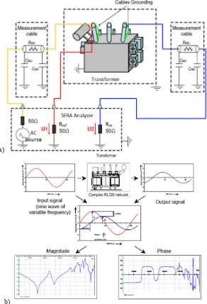
1.1.Sweep Frequency Response Analysis (SFRA)
a)
b)
Fig. 1. Illustration for SFRA concept (a) Measurement connection of SFRA to the transformer (b) Overview of SFRA measurement. [7-8]
Table 1. Frequency ranges used in SFRA results interpretation
Frequency Ranges Sensitive to Elements
Below to 10 kHz (Low sub-band) In this range phenomena linked with the transformer core and magnetic circuits are found.
5 kHz to 500 kHz (Middle sub-band) In this range phenomena linked with radial relative geometrical movements between windings are detected.
1.2.Electromagnetic forces under short-circuit conditions inside transformer
Inside a transformer, core and winding are the active elements to ensure its function to step-up/step-down voltage in power systems. For initial condition, the voltage is applied to the primary winding and develops a magnetic field surround of it. This magnetic field, B vector component known as magnetic flux, Ѱ is then flow through core (a ferromagnetic material) and transferred to the other secondary winding. Instead of focusing the magnetic field occurs around the winding, not to forget the electromagnetic force, F also initiated. This is because the winding itself is current carrying conductors therefore it is agreed according to the Eq. (1). The conductors of the winding will experience a force due to the interaction of electric current flow and magnetic fields.
(1)
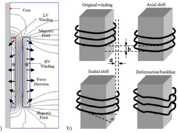
The actual transformer has been designed to withstand for a certain number of electromagnetic force originated from short-circuit. Unfortunately due to the late clearance of short-circuit from switchgear or circuit breaker, it will let the transformer winding tends to move or deform due to the force generated [10]. Fig 2 shows the concept transformer winding stress caused by current flow. In short-circuit condition; the actual current is around 8 – 10 times from the normal operating current thus developing very high electromagnetic forces [11]. This could lead the winding to deform in either axial or radial movement [12].
a) b)
Fig. 2. Illustration of electromagnetic forces in transformer (a) Magnetic field distribution and force direction in transformer winding (b) Graphical representation winding movement due to short-circuit current. [10-11]
2.Research Works
2.1.Results of SFRA
In this paper, a TNB in-service distribution transformer at PPU Seksyen 23 Shah Alam 30 MVA 33/11 kV Dyn11 is used to gain the SFRA measurement results. The transformer has been operated for almost 18 years but due to
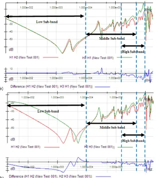
tripped on Buccholtz and Differential Relay; it has been suggested to take out from the system to analyze its condition. Other popular technique for transformer condition monitoring, DGA is used to extract any information from the insulation oil. The result showed the High Energy Arcing with little involvement of insulation paper [13]. Next, SFRA measurement is used to the transformer both high voltage (HV) and low voltage (LV) winding. The responses are then being compared with symmetrical phase winding. Discussions are made according to the selected proposed frequency ranges stated in the previous part to identify which parts are affected. Fig 3(a) and 3(b) are related to the HV phase winding comparison. Meanwhile Fig 4(a) and 4(b) are based on LV phase winding comparison.
In Fig 3(a), the comparison between SFRA graphical result between H1H2 phase to H3H1 phase shows no such deviation occurs in low and middle sub-band frequency ranges but not in high sub-band range. From the results, the possible faults occur is related to a low winding deformation in H1H2 and H3H1 phases winding. Meantime, in Fig 3(b) shows the comparison of SFRA graphical result in H1H2 phase to H2H3 phase. Comparison for these two curves in HV winding shows an obvious changes for low and high sub-band frequency ranges which indicate a possible faults related to the electrical faults (turn-to-turn winding short circuit) and winding deformation in the middle limb of transformer (H2H3 phase).
(a)
(b)
compared to H2H3 phase winding.
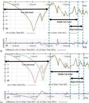
In Fig 4(a), the comparison between SFRA graphical result of x0x1 phase to x0x3 phase shows no such deviation occurs for overall frequency ranges. It means no mechanical deformation regarding to both core and winding in LV; x0x1 phase to x0x3 phase (both are in transformer outer limb). Meanwhile in Fig 4(b) shows the comparison of SFRA graphical result in x0x1 phase to x0x2 phase. The changes only occur in low frequency range and the possible fault parts are transformer core (especially in the middle limb) and turn-to-turn winding short circuit.
(a)
(b)
Fig. 4. SFRA measurement results for LV winding (a) x0x1 phase winding compared to x0x3 phase winding (b) x0x1 phase winding compared to x0x2 phase winding.
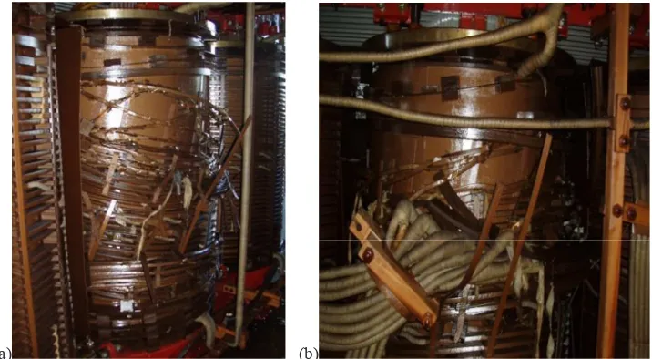
2.2.Validation from untanking process
deformation at HV winding especially in the middle limb of the transformer (H2H3 phase) and open connection from tap leads winding. The HV winding faults phase move downward because of the large electromagnetic forces originated from short circuit current produce an outer direction and make the upper layer of HV winding to disrupt downward the others.
(a) (b)
Fig. 5. Inspection inside transformer untanking process for (a) HV winding with H2H3 phase was observed to have moved downwards (Axial deformation). (b) Winding deformation at H2H3 phase also affected the tap leads winding.
3.Conclusion
In this paper, the SFRA method on diagnosing the condition of transformer main mechanical parts such as core and winding was investigated. The research work was conducted based on data taken from actual TNB transformer. By using the symmetrical phase comparison of both HV and LV windings it could be the best alternative way on interpret the SFRA measurement data besides on finding the transformer historical SFRA measurement data. From the validation process, it can be concluded that the SFRA measurement is a powerful techniques where it is able to pin-point the main defect of the transformer components [12-13]. For the next project, more case studies of actual in-service transformer will be validated to enhance the SFRA measurement advantages.
Acknowledgements
The authors gratefully acknowledge the reviewers of this paper for their valuable advice and guidance. The authors also appreciate to Dr. Yasmin Hanum Md Thayoob and Mr. Young Zaidey Yang Ghazali, for their best supervising on conducting this research project. Highly appreciation to Universiti Teknikal Malaysia Melaka (UTeM) and Ministry of Higher Education (MOHE) for the financial support to the authors.
References
Conference (PEOCO) Melaka, Malaysia, 2012 Ieee International, vol., no.,pp. 448-453, 6-7 June2012 doi: 10.1109/PEOCO.2012.6230906.
[2] Khiar, M.S.A.; Thayoob, Y.H.M.; Ghazali, Y.Z.Y.; Ab Ghani, S.; Chairul, I.S.; , "Condition assessment of OLTC using duval triangle and static winding resistance test," Power Engineering and Optimization Conference (PEOCO) Melaka, Malaysia, 2012 Ieee International , vol., no.,pp. 432-435, 6-7 June2012 doi: 10.1109/PEOCO.2012.6230903.
[3] Chairul, I.S.; Ghani, S.A.; Khiar, M.S.A.; Thayoob, Y.H.M.; Ghazali, Y.Z.Y.; , "Kraft paper insulation's life assessment and effects of oxygen and moisture to paper insulation's deterioration rate," Power and Energy (PECon), 2012 IEEE International Conference on , vol., no., pp.728-731, 2-5 Dec.2012 doi: 10.1109/PECon.2012.6450311.
[4] M.Wang, A.J. Vandermaar and K.D. Srivastava, “Review of condition assessment of power transformers in service” , IEEE Electrical Insulation Magazine, Vol. 18, No. 6, Nov/Dec 2002, pp 12-25.
[5] H.I. Septyani, H. Maryono, A.P. Purnomoadi, U.Sutisna, and Sumaryadi, “SweepFrequency response analysis for assessing transformer condition after an incident”, Diagnostic Measurement on Power Transformers Omicron electronics GmbH 2010.
[6] S.K. Joshi and A. Ray, “Application of sweep frequency response analysis for fault classification of transformer”, Diagnostic Measurement on Power Transformers Omicron electronics GmbH 2008.
[7] Omicron FRAnalyzer User Manual, “Sweep frequency response analyzer for power transformer winding diagnosis”, Omicron electronics 2009.
[8] J.L. Velasquez, M.A. Sanz-Bobi, M. Gutierrez and A. Kraetge, “Knowledge bases for the interpretation of the frequency response analysis of power transformers”, Congreso Internacional En Alta Tension Y Aislamiento Electrico Altae 2009.
[9] A. Contin, G. Rabach, J. Borghetto, M. D. Nigris, R. Passaglia and G. Rizzi, “Frequency-response Analysis of Power Transformers by Means of
Fuzzy Tools”, IEEE Transactions on Dielectrics and Electrical Insulation, June 2011, Vol. 18, No. 3.
[10] F. Marek and F. Jakub, “Transformer winding defects identification based on a high frequency method”, Meas. Sci. Technol. vol. 18, 2007, pp 2827-
2835.
[11] Nadim Mohamed. Ee Publishers. Electromagnetic forces in transformers under short circuit conditions. Retrieved date March, 20, 2013, from http://eepublishers.co.za/images/upload/Energize_2011_/07_TT_02_Electromagnetic.pdf.
[12] J.R. Secue and E. Mombello,” Sweep frequency response Analysis (SFRA) for the assessment of winding displacements and deformation in power transformers”, Electric Power Research 78, 2008, pp1119 – 1128.