Impact Wear Mechanisms
of DLC Coating
Impact Wear Mechanisms
of DLC Coating
Mohd Fadzli Bin ABDOLLAH
Advisor:
Professor Noritsugu UMEHARA
A dissertation submitted to the Department of
Mechanical Science and Engineering, Graduate School
of Engineering, Nagoya University
In partial fulfillment of the requirements for the degree
of Doctor of Engineering
Acknowledgements
Foremost, I would like to express my sincere gratitude to my advisor Prof.
Noritsugu UMEHARA for the continuous support of my Doctoral study and research,
for his patience, motivation, enthusiasm, and immense knowledge. His guidance
helped me in all the time of research and writing of this dissertation. I could not have
imagined having a better advisor and mentor for my study.
Besides my advisor, I would like to thank the rest of my dissertation
committee: Prof. Nobutada OHNO, Prof. Kenji FUKUZAWA and Assoc. Prof.
Hiroyuki KOUSAKA for their encouragement and insightful comments.
My sincere thanks to those who made this dissertation possible: Dr. Takayuki
TOKOROYAMA and Mr. Shinko SENDA from Nagoya University. I also wish to
thank Mr. Naruhiko INAYOSHI, Mr. Nobuyuki MIYAMOTO and Mr. Tsuyoshi
AKAO from DENSO Corporation.
It is honor for me to thank the scholarship from Universiti Teknikal Malaysia
Melaka (UTeM) for the financial support, including the cost of living and tuition fees
during my Doctoral study in Nagoya University.
Special thanks extended to my research partner, Mr. Yuto YAMAGUCHI for
the stimulating discussions. I have further to thank my colleagues from the Advanced
Materials and Manufacturing Laboratory for their support, encouragement, help, and
for all the fun we have had in the last three years. To my study leave officer, Mrs.
Siti Salwah Binti Ahmad from UTeM, many thanks for her great help in difficult
times.
I would like to give my special thanks to my parents, Abdollah Bin Baba and
Rosnah Binti Hasim, no words can describe my gratitude towards you. Both of you
have been the pillar of strength in my life. In you, I learned about empathy,
conscience, filiality and forgiveness. Thank you for your unlimited love, care and
support even at all times. To my siblings, it’s fortunate to be with you. My dearest
sisters, Hendon Binti Abdollah, Siti Zaleha Binti Abdollah, Siti Aisah Binti Abdollah,
and Siti Khairiah Binti Abdollah, for their love and encouragement. My dear brother,
Mohd Isa Bin Abdollah, for their kindness and source of motivation.
Last but not least, to my buddies, those who are still working on their Doctoral
study in Japan, Faiz Redza Bin Ramli, Nor Azmmi Bin Masripan, Mohd Khairi Bin
Mohamed Nor, Ahmad Anas Bin Yusof and Mohd Rizal Bin Alkahari, my sincere
thanks for your constant support for all the ups and downs, joy and sadness, laughter
and tears. Many years have passed and our friendship is still blooming, and I hope
our friendship will remain the same in the coming years. Many thanks to all Malaysia
students in Nagoya and many others who are not listed here for their friendship and
Abstract
Diamond-like carbon (DLC) films have been explored in the past due to their
highly attractive properties, such as high hardness; low friction coefficient; chemical
inertness and electrical insulation; optical transparency and smoothness; and
biological compatibility. In previous studies, most of the impact wear mechanisms of
DLC coatings are concerned with the fracture process in the coating due to the crack
propagation under severe wear conditions. However, no reports discuss about how
the impact wear mechanisms of the DLC coatings act under mild wear conditions.
Under impact, it is well known that plastic deformation should occur prior to the
impact wear. So, the first objective of this study is to identify the most significant
impact parameter that controls the deformation of DLC coating. After cyclic impacts,
though under mild wear conditions, it believes that impact wear should be occurring
by the phase transformation of DLC coating. Therefore, the second objective is to
clarify the impact wear mechanisms of DLC coating based on its phase
transformation. Finally, in order to distinguish more clearly between the plastic
deformation and impact wear of DLC coating as well as to predict its transition
points, a deformation-wear transition map has been proposed.
In this present study, DLC films were deposited on the tungsten high speed
steel (SKH2) substrate using physical vapor deposition (PVD) method. The impact
test was performed by using a horizontal impact tester for more than 102 impact cycles with a frequency of 10 Hz, and a drop-weight impact tester for low impact
cycles. The DLC coated SKH2 disc was repeatedly impacted by a chromium
molybdenum steel (SCM420) pin. The 90o inclination of impact tests were performed at room temperature under lubricated conditions. Prior to the impact test,
both disc and pin were cleaned using acetone in an ultrasonic bath. The maximum
normal impact load was obtained from the graph of normal impact load vs. time,
generated by a load cell. Besides, the contact impulse was determined from the area
below this graph. As for the absorbed energy, this can be determined using a high
From the experimental analysis, there is no unique relationship between the
residual impact crater volume/depth of DLC coating and contact impulse. The
highest coefficient of determination R2 for both the Vrand hr (R2hr = 0.9362 and R2Vr
= 0.9076) obtained from the response of maximum normal impact load. Besides,
there is an experimental error in the case of absorbed energy due to the microslip
effect. Furthermore, the impact phenomenon in this study can be considered as the
quasi-static indentation, where load is a governing parameter, because the impact
velocity is very low. By comparing with the analytical solutions, it is easier to predict
the residual impact crater volume/depth by static indentation analysis. Therefore,
from these reasons, it can be concluded that the residual impact crater volume/depth
is more affected by maximum normal impact load than absorbed energy.
From Raman spectroscopy analysis, it has been suggested that there is
pressure-induced graphitization since the impact testing was performed at the room
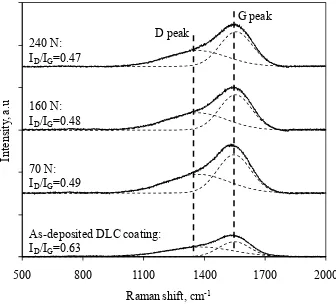
temperature. The phase transformation of wear debris and transfer layer from sp3 to sp2 induced graphitization process. However, the sp3 fractions of DLC coating on the crater surface are significantly increased with impact cycles as it is evidently shown
by decreasing ID/IG ratio approximately from 0.63 (as-deposited) to 0.47 (after 105 impact cycles), accompanied by a widening of full-width at half maximumof G peak
FWHMG (approximately from 179 cm-1 to 192 cm-1) with impact cycles. Besides the hardness reaches approximately to 21 GPa that is higher than as-deposited (17.14
GPa) after several impact cycles. This suggests the size of the larger sp2 clusters is reduced due to the mechanical crush of the larger sp2 clusters. Since the impact test was performed under atmospheric conditions, oxidation of iron with the environment
also occurs in the wear debris and transfer layer, where two predominant peaks of
magnetite (Fe3O4) and hematitie (α-Fe2O3) are observed from its Raman spectrum.
For a given material and controlled variables (pin radius, coating thickness,
substrate material, environmental conditions and so on), the proposed
deformation-wear transition map of DLC coating apparently shows that the maximum normal
impact load and impact cycles influence this transition. This empirical-based
transition map, which presents deformation and wear data in a graphical manner, is
able to provide a more global picture of how DLC coating behaves under cyclic
between the plastic deformation and impact wear of DLC coating were identified: (i)
Plastic deformation of the substrate, (ii) suppression of plastic deformation of the
substrate and (iii) wear of the DLC coating. Beyond the elastic limit, the DLC
coating only follows the plastic deformation of the substrate until several impact
cycles. Then, a suppression of plastic deformation of the substrate is taking place due
to the decreasing contact pressure with impact cycles to the yield point. The hardness
of the DLC coating on the crater surface is also increases after numerous impacts and
no wear has been observed within these two zones. Wear of the DLC coating
becomes dominant when the critical limit of maximum normal impact load and
impact cycles is exceeded. Experimental observations show that this wear is
associated with some degradation of the DLC coating. This includes the phase
transformation of the wear debris/transfer layer and propagation of radial cracks in
the DLC film as well as the formation of transfer layer on the counterpart material,
論
文
内
容
要
旨
ダ ヤ ン ド カ ボ ン 膜 。 ) 1 ( 膜 ) 高 硬 質 表 面 あ さ
小 さ く 耐 摩 耗 性 期 待 密 着 性 優 エ ン ン バ
ブ や カ 適 用 試 い 固 体 繰 返 接 触
衝 撃 摩 耗 金 属 い 研 究 進 い ) 1 ( 膜 い 摩 耗 基
本 特 性 及 び 摩 耗 カ ニ 不 明 あ 特 ) 1 ( 膜 繰 返 衝 撃 接
触 け 膜 破 壊 や 剥 カ ニ い 検 討 さ い
実 用 重 要 ) 1 ( 膜 脆 性 破 壊 伴 わ い 衝 突 条 件 摩 耗 い
摩 耗 基 本 特 性 及 び カ ニ 共 不 明 あ
本 研 究 物 理 蒸 着 法 高 速 度 工 具 鋼 S K H 「 デ 成 膜
水 素 含 有 ) 1 ( 膜 ロ ブ デ ン 鋼 S ( 2 4 「 0 ピ ン 衝 突 角 9 0 ま
い 試 作 装 置 室 温 油 中 衝 撃 摩 耗 実 験 行 い ) 1 (
成 膜 高 速 度 工 具 鋼 デ 変 形 及 び 摩 耗 特 性 明 詳 細
表 面 観 察 及 び 分 析 摩 耗 カ ニ 明 具 体 的 )
1 ( 成 膜 高 速 度 工 具 鋼 塑 性 変 形 含 摩 耗 及 最 大 衝 突 荷 重
衝 突 エ ネ 及 び 力 積 影 響 明 ) 1 ( 膜 繰 返
衝 突 け ) 1 ( 膜 衝 突 摩 耗 痕 及 び 相 手 ピ ン 移 着 物 構 造 分 析
行 い ) 1 ( 膜 構 造 変 化 伴 う 摩 耗 カ ニ 提 案 さ ) 1 (
膜 塑 性 変 形 摩 耗 分 評 価 方 法 提 案 ) 1 ( 膜 塑 性 変 形 摩
耗 カ ニ 最 大 衝 突 荷 重 衝 突 繰 返 数 遷 移 こ
) 1 ( 膜 変 形 - 摩 耗 形 態 遷 移 図 表 せ こ 明
第 章 緒 論
耐 衝 撃 摩 耗 期 待 さ ) 1 ( 膜 応 用 例 エ ン ン バ
ブ 及 び カ 使 用 条 件 解 説 ) 1 ( 膜 材 料 特 性 摩 擦
け 摩 擦 摩 耗 特 性 従 来 研 究 紹 介 金 属 及 び ) 1 ( 膜 衝 撃 摩 耗
衝 突 荷 重 ) 1 ( 膜 破 壊 関 従 来 研 究 あ 低 荷 重
衝 撃 摩 耗 け ) 1 ( 膜 摩 耗 特 性 及 び そ 摩 耗 カ ニ 研 究 成 果
無 い こ 述 こ 調 査 内 容 基 本 研 究 ) 1 (
膜 塑 性 変 形 含 摩 耗 特 性 及 最 大 衝 突 荷 重 力 学 的 因 子
影 響 解 明 繰 返 衝 突 伴 う ) 1 ( 膜 及 び 相 手 面 移 着 膜 構 造 変 化
詳 細 観 察 摩 耗 カ ニ 検 討 並 び 塑 性 変 形 摩 耗 分
分 析 ) 1 ( 膜 変 形 - 摩 耗 形 態 遷 移 図 提 案 行 う 背 景 述
第 「 章 繰 返 衝 突 け 最 大 衝 突 荷 重 衝 突 吸 エ ネ 及 び
力 積 ) 1 ( 膜 変 形 含 摩 耗 及 影 響
物 理 蒸 着 法 高 速 度 工 具 鋼 S K H 「 デ 成 膜 水 素 含 有 ) 1
( 膜 ロ ブ デ ン 鋼 S ( 2 4 「 0 ピ ン 衝 突 角 9 0 ま け 室 温
油 中 衝 撃 摩 耗 実 験 行 い 繰 返 衝 突 後 残 留 ) 1 ( 膜 摩 耗 痕
深 さ 及 び 体 積 及 最 大 衝 突 荷 重 衝 突 吸 エ ネ 及 び 力 積
影 響 明 最 大 衝 突 荷 重 衝 突 吸 エ ネ 及 び 力 積 )
1 ( 膜 デ 試 験 片 ロ ド 荷 重 時 間 応 答 及 び ピ ン 高
速 度 カ 衝 突 発 速 度 観 察 結 果 算 出 ) 1 ( 膜 厚 さ
」 . 0 m あ 潤 滑 油 灯 油 滴 最 大 衝 突 荷 重 「 0 0 ~
5 5 0 3 あ 衝 突 時 間 0 . 「 m 上 程 度 あ
そ 結 果 1 0
「
回 衝 突 い ) 1 ( 成 膜 高 速 度 工 具 鋼 摩 耗 痕
深 さ 及 び 体 積 最 大 衝 撃 荷 重 衝 突 吸 エ ネ 強 く 依 存
力 積 依 存 い こ 明 ) 1 ( 成 膜 場 合
成 膜 い 場 合 摩 耗 痕 深 さ 比 較 こ 同 あ こ
本 実 験 い 高 速 度 工 具 鋼 デ 塑 性 変 形 そ ) 1 ( 膜
表 面 摩 耗 深 さ い こ 明 更 実 験 結 果
解 析 結 果 比 較 結 果 ) 1 ( 膜 摩 耗 痕 深 さ 体 積 最 大 衝 撃 荷 重
最 大 荷 重 押 込 値 同 あ 推 定 可 能 あ 事
第 」 章 繰 返 衝 突 け ) 1 ( 膜 構 造 変 化
) 1 ( 膜 上 た 「
及 び 上 た 」
構 造 混 在 い 摩 擦 い 上 た
「
及 び 上 た 」
構 造 割 合 変 化 上 た
「
構 造 豊 富 ) 1 ( 相 手 面 移 着 摩
擦 摩 耗 特 性 影 響 及 報 告 あ 本 研 究 繰 返 衝 突 い
) 1 ( 膜 構 造 変 化 重 要 考 え そ こ ) 1 ( 膜 前 章 同
実 験 い 摩 耗 痕 及 び 相 手 面 移 着 物 マ ン 分 光 分 析 行 い 繰
返 衝 撃 試 験 け ) 1 ( 膜 構 造 変 化 明
そ 結 果 1 0
「
回 1 0
5
回 衝 突 繰 返 数 増 加 伴 ) 1 ( 膜
摩 耗 粒 子 相 手 面 移 着 物 上 た 「
構 造 豊 富 構 造 変 化 一 方 ) 1
( 膜 摩 耗 痕 上 た
」
構 造 豊 富 構 造 変 化 こ 明
さ ) 1 ( 膜 摩 耗 痕 硬 さ 1 7 G P a 「 1 G P a 増 加 こ 明
ロ ブ デ ン 鋼 移 着 物 ) 1 ( け く 酸 化 鉄
観 察 さ 本 結 果 ) 1 ( 膜 衝 撃 摩 耗 カ ニ ) 1 ( 膜 構
造 変 化 重 要 あ こ 明
第 4 章 繰 返 衝 突 け ) 1 ( 膜 変 形 - 摩 耗 形 態 遷 移 図
第 章 い ) 1 ( 膜 繰 返 衝 突 い 高 速 度 工 具 鋼 基 板
塑 性 変 形 生 い こ 明 そ こ 前 章 同
実 験 い ) 1 ( 膜 摩 耗 基 板 変 形 ) 1 ( 膜 断 面 詳 細 観 察
事 分 評 価 繰 返 衝 突 け ) 1 ( 膜 変 形 摩 耗 形 態 最
大 衝 突 荷 重 衝 突 繰 返 数 変 化 さ せ ) 1 ( 膜 変 形 - 摩 耗 形 態 遷 移 図
作 成 検 討 具 体 的 ) 1 ( 膜 繰 返 衝 突 後 摩 耗 痕 断 面 観
察 ) 1 ( 膜 厚 さ 減 少 量 測 定 そ 摩 耗 深 さ
) 1 ( 膜 繰 返 衝 突 後 表 面 摩 耗 痕 深 さ ) 1 ( 膜 摩 耗 深 さ 減
差 基 板 塑 性 変 形 深 さ
そ 結 果 衝 突 繰 返 数 1 0
「
回 程 度 基 板 塑 性 変 形 深 さ
摩 耗 痕 深 さ 大 部 分 あ そ 後 基 板 塑 性 変 形 停 止 ) 1 (
膜 摩 耗 始 こ 明 わ ) 1 ( 膜 主 変
基 板 塑 性 変 形 停 止 及 び ) 1 ( 膜 摩 耗 遷 移 こ
変 形 摩 耗 形 態 遷 移 最 大 衝 突 荷 重 増 加 伴 い 少 い 衝 突 繰
返 数 生 事 明 こ 結 果 第 章 ) 1 ( 膜 構
造 変 化 結 果 総 合 事 ) 1 ( 膜 衝 撃 摩 耗 カ ニ 繰 返
衝 突 上 た
「
豊 富 相 構 造 変 化 機 械 的 特 性 劣 化 構 造 変
化 層 ロ ブ デ ン 鋼 ピ ン 凝 着 あ 事 提 案 さ
第 5 章 結 論
以 各 章 得 知 見 い
以 本 論 文 物 理 蒸 着 法 高 速 度 工 具 鋼 S K H 「 成 膜
水 素 含 有 ) 1 ( 膜 ロ ブ デ ン 鋼 S ( 2 4 「 0 ピ ン 衝 突 角 9 0 ま
け 室 温 油 中 衝 撃 摩 耗 実 験 行 い ) 1 ( 膜 変 形 及 び 摩 耗 特 性 明
摩 耗 カ ニ 明 具 体 的 ) 1 ( 成 膜 高 速
度 工 具 鋼 デ 繰 返 衝 突 後 塑 性 変 形 量 摩 耗 量 詳 細 断 面
観 察 分 分 析 方 法 提 案 最 大 衝 突 荷 重 衝 突 繰 返 数
増 加 伴 う ) 1 ( 膜 塑 性 変 形 摩 耗 評 価 ) 1 ( 膜 繰 返
衝 突 け ) 1 ( 膜 衝 突 摩 耗 痕 及 び 相 手 ピ ン 移 着 物 構 造 分 析 行
Abbreviation
-Fe2O3 Hematite
a-C Hydrogen free diamond-like carbon
a-C:H Hydrogenated diamond-like carbon
AFM Atomic force microscopy
Cr-DLC Chromium diamond-like carbon
CVD Chemical vapor deposition
DLC Diamond-like carbon
EDS Energy dispersive x-ray spectroscopy
Fe Iron
Fe3O4 Magnetite
FE-SEM Field emission scanning electron microscopy
FIB Focused ion beam
FWHMG Full-width at half maximum of G peak GFRP Glass fiber reinforced polymer
H Hydrogen
ID/IG Raman intensity ratio = Intensity ratio of D peak to G peak
ISE Indentation size effect
MSIB Mass selected ion beam
PACVD Plasma assisted chemical vapor deposition
PLD Pulsed laser deposition
PVD Physical vapor deposition
RH Relative humidity
SCM420 Chromium molybdenum steel
SKH2 Tungsten high speed steel
ta-C Tetrahedral amorphous carbon
ta-C:H Hydrogenated tetrahedral amorphous carbon
Table of contents
Acknowledgements ... i
Abstract... iii
Abbreviation ... x
Table of contents ... xi
List of Figures... xiv
List of Tables ... xviii
1 Introduction ... 1
1.1 Industrial needs of DLC coatings ... 1
1.1.1 Plunger of diesel fuel injection ... 1
1.1.2 Bucket of engine valve train ... 3
1.2 DLC coatings ... 5
1.2.1 Structure and deposition of DLC coatings ... 6
1.2.2 Tribological properties of DLC coatings for sliding contact ... 8
1.3 Impact wear ... 12
1.3.1 Impact wear of metals ... 12
1.3.2 Impact wear of DLC coatings ... 14
1.4 Purposes of study ... 19
1.5 Outline of dissertation ... 20
References ... 23
2 Effect of impact load, absorbed energy and contact impulse on the deformation of DLC coating under impact ... 26
2.1 Introduction ... 26
2.2 Experimental method ... 28
2.2.1 Materials ... 28
2.2.2 Impact testing ... 29
2.2.3 Residual impact crater volume/depth ... 31
2.3 Theoretical background ... 32
2.4 Results and discussion ... 37
2.4.1 Morphology observations of impacted DLC coating ... 37
2.4.3 Experimental relationship of the residual impact crater
volume/depth with a maximum normal impact load, absorbed
energy and the contact impulse ... 41
2.4.4 Comparison of experimental results and analytical solutions ... 44
2.5 Conclusions ... 46
References ... 47
3 Phase transformation of DLC coating under cyclic impact loading... 49
3.1 Introduction ... 49
3.2 Experimental method ... 50
3.2.1 Raman spectroscopy analysis ... 51
3.3 Results and discussion ... 52
3.3.1 Phase transformation of DLC coating on the crater surface ... 52
3.3.2 Phase transformation of wear debris and transfer layer ... 56
3.3.3 Oxidation of iron (Fe) in the wear debris and transfer layer ... 62
3.4 Conclusions ... 63
References ... 64
4 Deformation-wear transition map of DLC coating under cyclic impact loading ... 66
4.1 Introduction ... 66
4.2 Experimental method ... 68
4.2.1 Impact testing ... 68
4.2.2 Transition of contact pressure ... 69
4.2.3 Wear measurements ... 70
4.2.4 Construction of the deformation-wear transition map... 72
4.3 Results and discussion ... 74
4.3.1 Deformation-wear transition map ... 74
4.3.1.1 Plastic deformation of the substrate zone ... 75
4.3.1.2 Suppression of plastic deformation of the substrate zone . 76 4.3.1.3 Wear of the DLC coating zone ... 77
4.3.3 Future developments of deformation-wear transition map ... 81
4.4 Conclusions ... 86
References ... 87
List of publications ... 91
International journals ... 91
International conferences/symposiums/workshops ... 92
List of Figures
Figure no.
1.1 Schematic illustration of the DLC coated plunger inside the barrel of diesel fuel injection and its impact process when the fuel is injected
directly into the cylinder ... 2
1.2 Schematic illustration of the future DLC coated bucket-type valve train and its impact process during cam rotational cycle. (a) Completed closing of valve during the combustion stroke and (b) Valve opened during
the intake and exhaust stroke. Half of the illustration is from [5] ... 4
1.3 The bonding configuration and typical Raman spectrum of diamond,
DLC and graphite [8] ... 7
1.4 Ternary phase diagram of sp2, sp3, and hydrogen contents of various
forms of DLC [16] ... 7
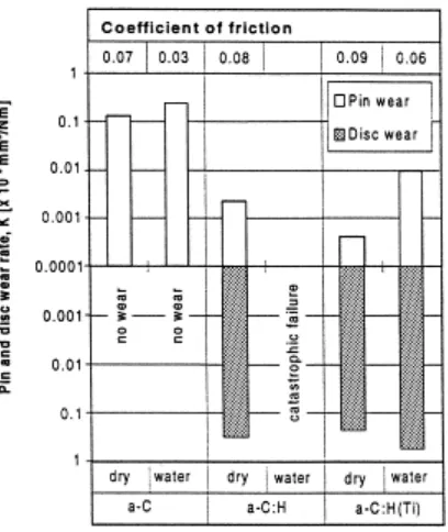
1.5 The friction coefficient values, the wear rates of the steel pins and the wear rates of the uncoated, a-C, a-C:H and a-C:H(Ti)-coated substrates in dry (50% RH) and oil-lubricated tests with mineral base oil and mineral oil with EP additives. The normal force was 10 N and the sliding
velocity 0.004 ms-1 [31] ... 10 1.6 The friction coefficient values, the wear rates of the alumina pins and
the wear rates of a-C, a-C:H and a-C:H(Ti)-coated substrates in dry (50% RH) and water-lubricated test. The normal force was 5 N
and the sliding velocity 0.004 ms-1 [31] ... 11 1.7 Schematic illustration of the mechanisms of impact wear [35] ... 13
1.8 Failure modes of DLC coatings under repeated impact test [1] ... 16
1.9 Wear of (a) W-DLC (b) Cr-DLC1 and (c) Cr-DLC2 coating
in the high-load regime [39] ... 17
1.10 Wear of (a) W-DLC and (b) Cr-DLC2 coating
in the low-load regime [17] ... 17
1.11 Evolution of the formed blister as a function of the number of cycles for a DLC coating at 120 N impact load. a) After 2 x 10⁶ impact cycles
b) after 3 x 10⁶ impact cycles and c) after 7 x 10⁶ impact cycles [40] ... 18 1.12 Outline of dissertation ... 22
2.2 Schematic illustration of the repeated impact tester ... 30
2.3 Area below the graph of F vs. t, which generated by a load cell,
is similar to the contact impulse Ft ... 30 2.4 (a) Discretions of x-axis of an impact crater to n cross sections, with the
thickness of ∆x, and(b) determination of each surface area (A-A cross section) using the integration function in Origin 8.1 ... 31
2.5 (a) Profile of contact surface during impacting at the maximum normal impact load Fz, and(b) the remaining permanent impact crater
at the end of impact ... 36
2.6 FE-SEM cross-sectional view of the FIB-milled DLC coating on the SKH2 substrate (tilted at 60o); where (a) h60c1 is the non-impacted film thickness, and (b) h60c2 isthe impacted film thickness ... 37 2.7 EDS maps of the affected area on the SCM420 pin surface ... 38
2.8 The biggest difference between axand ay is caused by the effects
of microslip ... 38
2.9 The residual depth of crater, with or without DLC coating on the
SKH2 substrate after impact at 400 cycles ... 39
2.10 AFM observations of the residual impact crater of DLC coating on the SKH2 substrate and its cross sectional profile (A-A cross section).
All conditions show hr< 5hc ... 40
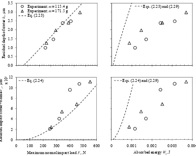
2.11 Experimental relationship between the residual impact crater volume/depth of DLC coating and the maximum normal impact load, absorbed energy, as well as the contact impulse. The dashed line indicates the best
fitting curve ... 43
2.12 Experimental and analytical comparison of the residual impact crater volume/depth of DLC coating, as a function of maximum normal impact load and absorbed energy ... 45
3.1 Raman spectra of the DLC coating on the craters surface after
105 impact cycles under different maximum normal impact loads ... 53 3.2 Variation of (a) FWHMG, and
(b) Raman intensity ratio ID/IG with impact cycles ... 54
3.3 Nanoindentation test at the surface of impact craters with respects to
impact cycles ... 55
3.4 AFM topography images at the surface of impact craters and its arithmetic average of surface roughness Ra under different
3.5 FE-SEM micrographs of the affected area on the SCM420 pins
(a) under different maximum normal impact loads and impact cycles, and
(b) as-received ... 58
3.6 Raman spectra of the transfer layer on the affected area of the SCM420 pins under different impact cycles at a maximum normal impact load of 240 N .... 59
3.7 Raman spectra of the wear debris under several maximum normal
impact loads after 104 impact cycles ... 60 3.8 FE-SEM micrograph of the wear debris taken from the edge
of impact crater. The top left micrograph is an impact crater ... 60
3.9 EDS elemental composition (within a small rectangle on the FE-SEM micrograph) of the transfer layer on the affected area of the SCM420 pin after 105 impact cycles at 240 N and compared with the as-received ... 61 4.1 Schematic illustration of the drop-weight impact tester ... 68
4.2 FE-SEM cross-sectional view of the FIB-milled DLC coating on the SKH2 substrate (tilted at 60o); where h60c1 is the non-impacted film thickness, and
h60c2 is the impacted film thickness. The equations at the top right are for the wear depth hw calculation ... 70
4.3 Schematic illustration of the wear depth hw ... 71
4.4 Residual impact crater volume of the impacted DLC coating, plotted as a function of (a) maximum normal impact load, and (b) impact cycles (Arrows indicate the onset of load/cycle-dependent deformation-wear
transitions) ... 73
4.5 Deformation-wear transition map of DLC coating under cyclic impact
loading ... 74
4.6 Comparison of the residual depth of the impact crater hr and the plastic
deformation depth hp as a function of impact cycles. The difference
between both curves (patterned in vertical lines) gives the approximate
wear depth of the DLC coating ... 75
4.7 Relationship between mean contact pressure and impact cycles ... 76
4.8 The EDS maps (within a small rectangle in the FE-SEM micrograph)
of the transfer layer on the affected area of the SCM420 pin ... 79
4.9 Raman spectrum of the wear debris and transfer layer after 104 and 105 impact cycles at 240 N, respectively. The Raman spectrum of the as-received
4.10 The FE-SEM cross-sectional view of the FIB-milled DLC coating on the SKH2 substrate shows radial crack formation in the impacted area of
the DLC film after 104 impact cycles at 240 N ... 80 4.11 Illustration of the formation of radial crack ... 80
4.12 Residual depth of crater for DLC coating on SKH2 substrate impacted by two different SCM420 pin radii. Blue line for pin radius of 1 mm
and red line for pin radius of 1.5 mm ... 83
4.13 Transfer layer on the SCM420 pin impacted at the same maximum
normal impact load with different mean contact pressure. ... 84
4.14 (a) Transfer layer on the SCM420 pin impacted at the same maximum normal impact load with different impact velocity and
(b) EDS map of the transfer layer on the SCM420 pin. ... 84
4.15 Raman spectrum of the transfer layer at the higher impact velocity
List of Tables
Table no.
1.1 The fundamental characteristics of a-C:H and ta-C films [21] ... 9
2.1 Material properties of the DLC, SKH2 substrate and SCM420 pin ... 28
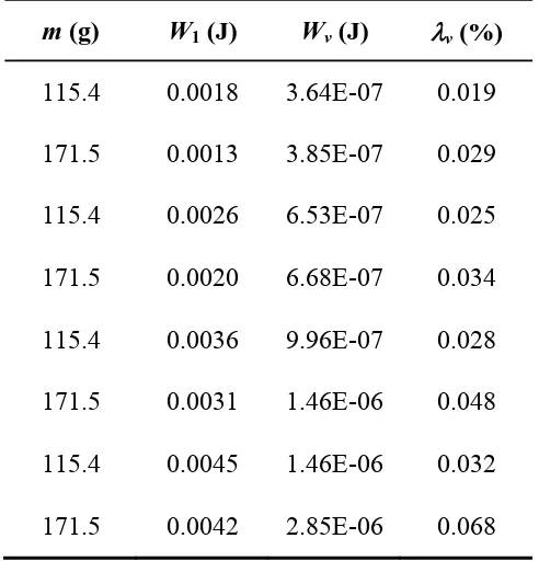
2.2 Fraction of vibrational energy Wv to the initial kinetic energy W1 ... 44
Chapter 1
Introduction
1.1 Industrial needs of DLC coatings
1.1.1 Plunger of diesel fuel injection
For modern environmentally friendly cars we need engines with low emissions
and with reduced fuel consumption. On the other hand, we would like to have a fun
driving experience and we want to buy a car at the lowest price possible. Gasoline
and diesel fuel injection systems provide the basis for the car manufacturer to fulfill
these targets. The gasoline direct injection system sprays the exact needed quantity of
fuel directly into the cylinder of the engine. It allows a higher compression and a
more efficient combustion process and can be flexibly adjusted for economical as
well as sportive driving. Furthermore, direct gasoline injection reduces pollutant
emissions to levels that will meet the even tougher US laws of the future. Diesel
engines have a higher degree of efficiency in their use of the fuel energy. In Europe,
more than 40% of all new cars are equipped with a diesel engine, including high
class cars. High-pressure injection systems with pressures up to 200 MPa give the
best results for combustion [1].
In direct injection diesel engine applications, a fuel injector is a precision
device that must meter the quantity of fuel required for each cycle of engine and
must develop the high pressure necessary to inject the fuel into the combustion
chamber at the correct instant of the engine operating cycle. Many fuel systems
presently used in direct injection diesel engines utilize a hydraulically actuated
and/or electronically controlled fuel injector to pressurize the fuel charge to obtain
the desired fuel spray pattern and fuel volume into the combustion chamber at the
precise moment. These hydraulically actuated and/or electronically controlled fuel
injectors often use very compact and high precision moveable components to achieve
the prescribed delivery of fuel at the desired time and for the desired duration.
As a result of the compact nature of many fuel injector components together
with the harsher environment, the stresses and forces present within an operating fuel
area of the smaller components, which spread out the higher contact forces and
stresses, increases adhesive and abrasive wear at the contact surfaces, such as the
nozzle tip and check interface. In addition, fuel injectors and fuel injector
components require superior harness characteristic and lubricity characteristics to
combat the higher contact stress. The maximum contact pressure approximately
1.5 GPa is located at the tip point as shown in Fig. 1.1. Ignition occurs in a diesel
engine by injecting fuel into the air charge, which has been heated by compression to
a temperature greater than the ignition point of the fuel or about 538°C.
Therefore, the disclosed thin film diamond-like carbon (DLC) coatings for fuel
injector components such as fuel injector needles (was patented on April, 2004 [2])
are particularly useful in highly loaded, marginally lubricated fuel injection system
applications where component wear (both sliding and impact type) are typically
encountered. The thin film minimized abrasive and adhesive wear.
However, the complex interaction between many coating types, contact
combination, operating temperature, contact geometry and load and etc. indicate that
the DLC coating require extensive future research to provide optimum combination
for different applications especially under mild wear conditions.
Fig. 1.1 Schematic illustration of the DLC coated plunger inside the barrel of diesel
fuel injection and its impact process when the fuel is injected directly into the
cylinder.
Plunger Spring
Seat fuel fuel
U
p
w
ar
d
/d
ow
nw
ar
d
m
o
ti
o
n
DLC coating
Normal
1.1.2 Bucket of engine valve train
The valve train is the engine component that controls the timing of the inlet and
exhaust valves. Many systems have been employed for controlling valve timing and
designs have commonly used the application of cams with a combination of pushrods,
rocker-arms and/or lifters in a variety of configurations.
The valve opening and closing sequence for all chambers is controlled from the
valve train by the relative rotational position of the individual cams. In bucket-type
valve trains (bucket is also known as tappet), valves are actuated directly. No
transmission mechanism is required between valve and camshaft. The cam stroke is
transmitted directly to the valve via the bottom of the bucket. As the camshaft rotates,
the eccentricity of an individual cam's shape brings it into contact with the bucket
surface, where the two surfaces are in both sliding and rolling contact. The cam's
continued rotation causes depression of the bucket, compression of the valve spring,
and depression of the valve stem, opening the valve. As the camshaft rotation
continues, the contact passes the most eccentric point of the cam after which
momentum and the force of the valve-spring return the valve train components to
their initial state. During a typical camshaft cycle there are a number of forces
applied to the cam–bucket contact that influence the tribology of the system, which
gave a maximum contact pressure of approximately 445 MPa at the temperature of
105oC [3]. The forces at the point of contact vary in magnitude depending on the point in the cycle, the lubrication regime and the steady-state camshaft rotational
speed. It is the impact loading that is of interest in this study. It is common for the
travel of the valve-stem to be limited by the complete closing of the valve in order to
avoid unnecessary friction losses. The force of keeping the spring compressed is
borne by the valve-stem and valve-seat. The limited valve-stem movement also
causes separation of the cam and tappet surfaces for approximately 55% of the cycle.
At the point where the cam rotation brings the cam and bucket back into contact, the
load from the compressed spring is transferred from valve-stem and valve-seat to the
cam–bucket contact, as shown in Fig. 1.2 (b).
In order to protect the top surface of bucket from continuous wear due to the
cyclic contacts with the camshaft, DLC coatings can potentially be used to provide a
Kano [4], the tetrahedral amorphous carbon (ta-C) coated cam follower of the bucket
type has been applied to gasoline engines from autumn 2006 for the first time in the
world.
Even though an alternative solution by using the DLC coatings has practically
applied in the industry, nobody knows how the impact wear mechanisms of the DLC
coating acts in low-load regime. This requires an extensive future research.
Fig. 1.2 Schematic illustration of the future DLC coated bucket-type valve train and
its impact process during cam rotational cycle. (a) Completed closing of valve
during the combustion stroke and (b) Valve opened during the intake and exhaust
stroke. Half of the illustration is from [5].
Normal load,Fz
U
p
w
ar
d
a
n
d
d
o
w
n
w
ar
d
m
o
ti
o
n
Camshaft
Bucket
Valve spring
Valve-stem
Valve-seat
Valve guide
Head
DLC coating
Separation during half of cycle
Spring forces
1.2 DLC coatings
Carbon is one of the commonest elements throughout the universe. In the
nature carbon is found as diamond, graphite and amorphous carbon. The name of
DLC was first coined by Aisenberg in 1971 to describe the hard carbon films that he
prepared by direct deposition from low energy carbon ion beams [6]. Now, DLC is
the name commonly accepted for hard carbon coatings which have similar
mechanical, optical, electrical and chemical properties to natural diamond, but which
do not have a dominant crystalline lattice structure.
DLC films have received much attention over recent years and been under
intensive research since the middle of 1980s [7]. Besides, DLC owing to the broad
range of applications where they can offer tribological benefits. DLC is a generic
term that is used to describe a range of different amorphous carbon films whose
properties range considerably depending on deposition conditions and method. DLC
films are thin, usually in the region of 1–4μm in thickness and have wide ranging
properties. The main factor that controls their properties is the proportion of sp2 (graphitically-bonded) to sp3 (diamond-bonded) carbon atoms but additional factors such as the presence of silicon, hydrogen, nitrogen and metal dopants, the use of
interlayers to promote adhesion and tailor residual stress levels, the surface
roughness and interaction with lubricants are also key to their ultimate performance.
DLC is not simply a single solution to a tribological problem as the range of
mechanical properties and the potential for different tribochemical reactions with
these films is vast. DLC films include hydrogenated DLC (a-C:H), hydrogenated
tetrahedral amorphous carbon (ta-C:H); hydrogen free DLC (a-C); tetrahedral
amorphous carbon (ta-C); and those containing dopants of either silicon or metal
such as Si-DLC and Me-DLC, respectively. These materials depict the following
valuable properties: Resistance to wear as the cause of a very high hardness; low
friction coefficient; chemical inertness and electrical insulation; optical transparency
1.2.1 Structure and deposition of DLC coatings
Carbon has three different types of bonding configurations, namely sp3, sp2 and sp1. The bonding configuration of carbon atom in diamond, DLC and graphite are illustrated in Fig. 1.3 [8]. In diamond, carbon has four sp3 hybridized orbitals. These sp3 orbitals contribute to the formation of four equal carbon-carbon bonds with adjacent atoms, which produces the tetrahedral structure of diamond. This covalently
bonded tetrahedral structure is the origin of the superior properties of diamond, like
high hardness and high thermal conductivity. Graphite has three trigonally directed
sp2 hybrid orbitals, which lie in plane. Each carbon atom in plane is bonded to three other carbon atoms with strong covalent bonds. The layers of carbon atoms are
attracted to each other by weak Van der Walls forces producing the layered structure
of graphite. The layers can cleave easily, which accounts for the typical low friction
property of graphite [9-10]. The DLC films have a mixed sp3/sp2 structure with different proportions of sp3 and sp2 bonds depending on the deposition techniques and deposition parameters used. The structure is claimed to consist of sp2 bonded clusters embedded in an amorphous sp3 bonded carbon matrix [11-12]. So the term “diamond-like” emphasizes a set of properties akin to diamond and, at the same time
implies the absence of crystalline diamond order [13].
Basically, a-C:H is an amorphous network composed of carbon and hydrogen.
The properties of these coatings depend strongly on the hydrogen content and the
sp3/sp2 content, which in turn, depend on the deposition process and its parameters [14]. The hydrogen is important for obtaining a wide optical gap and high electrical
resistivity and stabilizing the diamond structure by maintaining the sp3 hybridization configuration [15]. For a-C films, hydrogen is generally treated as an impurity. The
hydrogen-free amorphous carbon, which is highly sp3 bonded, is known as ta-C. The compositions of DLC can be displayed on a ternary phase diagram of sp3 ratio, sp2 ratio and hydrogen content of the film, as shown in Fig. 1.4 [16].
DLC coatings are formed when ionized and decomposed hydrocarbon or
carbon species hit the surface with energies ranging from several tens of eV to
200 eV [17]. All methods for the deposition of DLC films are non-equilibrium
growing films. The methods can be divided into chemical vapor deposition (CVD)
and physical vapor deposition (PVD) techniques. The CVD techniques, such as d.c.
plasma and radio frequency (r.f.) plasma assisted CVD; and PVD techniques, like
sputter deposition, ion-plating techniques and ion beam techniques can be used for
depositing the a-C:H coatings. The PVD techniques, such as magnetron sputtering,
mass selected ion beam (MSIB), cathodic arc and laser plasma deposition can be
used for a-C and ta-C coatings [16],[18-19]. DLC coatings can be deposited at
temperatures that are below 200oC [20] to 325oC [15]. This property makes it possible to deposit DLC coatings on most relevant engineering materials, including
polymers.
Fig. 1.3 The bonding configuration and typical Raman spectrum of diamond, DLC
and graphite [8].
Fig. 1.4 Ternary phase diagram of sp2, sp3, and hydrogen contents of various forms of DLC [16].
1.2.2 Tribological properties of DLC coatings for sliding contact
The tribological behaviour of DLC is strongly influenced by the film
deposition conditions, the tribological conditions and especially the atmosphere
during operation. The fundamental characteristics of the a-C:H coatings and ta-C
coatings are represented in Table 1.1 [21].
The pulsed laser deposition (PLD) a-C films have a coefficient of friction less
than 0.1 in vacuum and 0.03 in dry nitrogen [22]. Voevodin et al. [23], Huang et al.
[24] and Eskusson et al. [25] studied a-C coatings prepared by a PLD technique.
Voevodin et al. [23] showed the formation of graphite-like transfer layer during
sliding friction. The sp3 to sp2 phase transformation was observed after several thousands of sliding cycles. Besides, Erdemir et al. [26] also discovered the same
phenomenon on pin wear surface after a long sliding distance against a-C:H coating
produced by Ion Beam Deposition. The surface graphitization was found to be
responsible for low friction in humid air, and for high friction in vacuum. In addition,
Huang et al. [24] showed that the G-peak width and the intensity ratio (ID/IG) of DLC film were found to be sensitive to the structural changes induced by the change of the
deposition temperature. The total sp3 fraction in the DLC film remains almost constant at a temperature less than 200oC and shows a sharp decrease at a temperature greater than 200oC. Eskusson et al. [25] suggested that laser irradiation intensity has noticeable influence on the structure and hybridization of carbon atoms
deposited. At higher irradiation intensities, the graphitization of the amorphous films
was observed. The a-C films deposited by cathodic vacuum arc, were found to give
coefficient of friction values in the range of 0.04 to 0.18 in ambient atmospheres [20].
The properties of DLC films can be changed or tailored by different techniques.
Alloying the DLC structures can be used to inhibit the triboactivity of the a-C:H
coatings. Different alloying techniques may also be used to reduce the internal
stresses of the DLC coatings. Alloying a-C:H films with different metals generally
reduces the compressive stresses to values below 1 GPa. The tribological of
metal-alloyed a-C:H films has been explained by a combination of ceramic-like properties
The a-C:H and ta-C coatings showed some variation in tribological
performance in the different tests carried out. In dry sliding conditions, the wear of
the ta-C coating was lower compared to the a-C:H coating, which was due to the
high hardness and high stability of the ta-C film. On the other hand, wear of the
counterpart materials against ta-C coating was about one order of magnitude higher
compared to that of the a-C:H coating. However, the coefficient of friction of ta-C
coating in dry air reached high values compared to a-C:H carbon coating [28-31].
The a-C:H coating suffered from catastrophic wear in water soon after the beginning
of the test and the coating could not survive under water lubrication [31-32].
Conversely, the ta-C performed well with water lubrication, since no measurable
wear could be detected. The pin wear rates increased against both a-C:H and ta-C
coatings. However, the coefficient of friction is significantly lower, particularly for
the ta-C coating. Furthermore, the wear and the coefficient of friction of both a-C:H
and ta-C coatings decreased when oil lubrication was applied, even though the
additives used in the oils [31-32]. This shows that a-C:H and ta-C coatings have
excellent performance in oil-lubricated conditions. Considering the utilization of
DLC films in practical components, it is suggested that the a-C:H and particularly the
ta-C coating can be used not only in dry conditions, but also in boundary lubricated
conditions for providing safe operation in demanding operating conditions. However,
the oil lubrication prevented the formation of the tribolayer on the pin wear surface
in the same manner as the water lubrication, which increased the pin wear to some
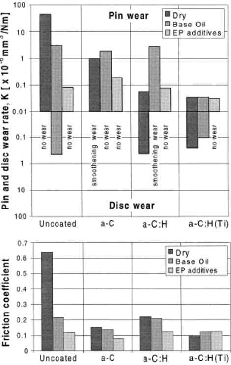
extent. Fig. 1.5 and Fig. 1.6 summarize the tribological properties of DLC coating in
dry, water- and oil-lubricated conditions [31].
Table 1.1 The fundamental characteristics of a-C:H and ta-C films [21].
Coating
Deposition parameters Coating properties
UB
V
p pa
Temp.
o
C
H-content
%
sp3 bonding
%
Hardness GPa
Young`s Modulus
GPa
a-C:H -550 5.5 100 26-33 70 141 1295
ta-C - 3 x10⁻⁴ 60 <1 60a 1518 44557
a
Fig. 1.5 The friction coefficient values, the wear rates of the steel pins and the wear
rates of the uncoated, a-C, a-C:H and a-C:H(Ti)-coated substrates in dry (50% RH)
and oil-lubricated tests with mineral base oil and mineral oil with EP additives. The
Fig. 1.6 The friction coefficient values, the wear rates of the alumina pins and the
wear rates of a-C, a-C:H and a-C:H(Ti)-coated substrates in dry (50% RH) and
water-lubricated test. The normal force was 5 N and
1.3 Impact wear
Impact wear can be defined as wear of a solid surface due to repetitive
exposure to dynamic contact by another solid body [34]. Some researchers
investigated impact wear of metals and DLC coatings as described in the following
section.
1.3.1 Impact wear of metals
For metal impact pairs, the behavior of impact wear involves elastic and plastic
deformation when impact loading or impact energy is high and/or fatigue
accompanied by wear debris release due to crack formation [35-36]. If oxygen is
present and the wearing material can be oxidized then a corrosive or oxidative wear
mechanism can also take place. The mechanisms of impact wear are illustrated
schematically in Fig. 1.7 [35].
In general, impact wear of metals is dependent on the formation of deformed
layers, particularly when wear by fatigue or crack formation is predominant [37]. In
such cases, subsurface cracks extend parallel to the surface in a manner very similar
to `delamination` wear. The material through which the cracks propagate is very
often plastically deformed and work-hardened as a result of contact stresses during
impact [37]. Spallation and wear by crack formation can also occur in relatively
brittle materials [38]. Therefore, the presence of surface plastic deformation, in some
cases, is not essential to this form of wear.
The type of material sustaining impact wear has a strong effect on the wear
mechanism. Metals are prone to an oxidative form of impact wear while ceramics
wear by cracking and spalling. Polymers tend to wear by plastic deformation, fatigue
cracking or by chemical attack from hot compressed layers of oxygen and pollutants
at the moment of impact.
Sufficient hardness of the impacted component is necessary to prevent rapid
wear or extrusion of material from the contact by plastic deformation. In most
situations this condition can be fulfilled by assuring an adequate hardness and then
wear is controlled by other material characteristics. For example, wear by spalling or
crack formation is controlled by brittleness and microstructure. The use of materials
by crack formation. Brittleness favors rapid crack growth and the formation of very
large spalls or even macroscopic fracture of the component [38] while crack
initiation is facilitated by inclusions [37].
Lubricants are useful in controlling impact wear in applications where they can
be reasonably applied and providing that the lubricant does not cause chemical attack
on the contacting surfaces. Hydrodynamic squeeze films can separate contacting
surfaces for the duration of impact and the absence of sliding ensures that contact
temperature rises are relatively small so that lubrication by adsorbed films is feasible.
The basic limitation of lubricants, however, is their inability to significantly reduce
the contact stresses during impact and wear is therefore only partially suppressed.
1.3.2 Impact wear of DLC coatings
According to the previous studies [1],[39-40], impact wear mechanisms of the
DLC coating are concerned with the fracture process in the coating due to the crack
propagation under severe wear conditions. All the repetitive impacts used in these
studies involve either only normal loading [1],[40] or under combined normal and
tangential loading [39]. However, no reports discuss about the tribological properties
of DLC coating under impact conditions.
Treutler [1] found two types of failure modes of DLC coating under repeated
impacts. He also found that the endurance limit of DLC coating depending on the
impact load and impact cycles. The first mode is the interface failure, in which the
coating loses adhesion to the substrate due to shear and tensile stress. Cracks may
start from defects at the interface and sometimes cause catastrophic failure with
delamination of rather big flakes of the coating. Normally, the wear starts at the
edges of the spherical calotte (where the maximum of the shear stress is located) (Fig.
1.8). However, even with the best coatings, the second failure mode can be found if
the load is high enough. The second mode is wear and fatigue of the coating or, in
other words, the cohesive failure mode. It normally consists of a continuous removal
of the coating, starting from the middle of the spherical calotte. The fatigue occurs
due to periodical stress loads and shows micro cracks within the coating.
Three different types of DLC coatings under a non-lubricated repetitive
inclined impact test were studied by Zanoria and Seitzman [39]. One is tungsten
diamond-like carbon (W-DLC) and the other two are chromium diamond-like carbon
(Cr-DLC) made from different deposition recipes. The typical wear events that lead
to failure of the coating, characterized by exposure of the substrate, are (i) formation
of partial ring cracks at the trailing edge of the impact crater, (ii) thinning of the top
coating due to sliding wear, (iii) formation of through-thickness shear cracks in the
top layer, (iv) delamination of the top layer from the interlayer, (v) formation of
through-thickness cracks in the interlayer, (vi) delamination of the interlayer from
the substrate. In the high-load regime, as shown in Fig. 1.9, the poor fracture
resistance of both the top layer and interlayer causes the very low impact wear life of
Cr-DLC2 compared to that of the Cr-DLC1 coating is attributed primarily to the high
resistance of the top coating to shear-induced fracture. In the low-load regime, as
shown in Fig. 1.10, in which shear cracks were not observed, the poor wear life of
the W-DLC coating relative to the Cr-DLCs is attributed mainly to the low fracture
resistance of the interlayer. In contrast, the interlayer of the Cr-DLC coatings have
adequate fracture strength to temporarily provide secondary protection to the
substrate after the top coating has been delaminated.
Ledrappier et al. [40] focused on the spalling phenomena of DLC coatings,
obtained by plasma assisted chemical vapor deposition (PACVD), under repeated
impact conditions. Spalling may lead to a catastrophic failure. The spalls slowly
grow and coalesce as a function of number of impacts and applied normal load. The
mechanism responsible for this spallation phenomenon was due to the blister failure
on DLC coatings. Some hypotheses for this unusual behavior are proposed in
reference to the film mechanical properties and residual stresses level. The blister
may be considered as the result of a classical buckling phenomenon. Once the first
small buckle is obtained, the size of the formed buckle remains stable. No further
growth is observed. Blisters may eventually interact with each other and coalesce
later on. Due to the repeated impacts, buckles undergo cyclic loadings that may
induce failure and spall formation. This slow blistering evolution is illustrated on Fig.
1.11. For thicker films, an interfacial delamination occurred rather than a film
buckling but required high compressive stress level. The buckle formation and
stability then directly depend on the film thickness and residual stress level in the
Fig. 1.9 Wear of (a) W-DLC (b) Cr-DLC1 and (c) Cr-DLC2 coating
in the high-load regime [39].
Fig. 1.10 Wear of (a) W-DLC and (b) Cr-DLC2 coating
[image:37.595.163.448.431.636.2]Fig. 1.11 Evolution of the formed blister as a function of the number of cycles for a
1.4 Purposes of this study
According to the previous studies that have been described in Section 1.3.1,
impact wear mechanisms of DLC coatings are concerned with the fracture process in
the coating due to the crack propagation under severe wear conditions. Besides,
nobody will use the DLC under this condition that may lead to a catastrophic failure
and should be avoided in most industrial cases. However, no reports discuss about
how the impact wear mechanisms of DLC coatings acts under mild wear conditions.
Under impact, it is well known that plastic deformation should occur prior to the
impact wear. So, the first objective of this study is to identify the most significant
impact parameter that controls the deformation of DLC coating. After cyclic impacts,
though under mild wear conditions, it believes that impact wear should be occurring
by the phase transformation of DLC coating. Therefore, the second objective is to
clarify the impact wear mechanisms of DLC coating based on its phase
transformation. Finally, in order to distinguish more clearly between the plastic
deformation and impact wear of DLC coating as well as to predict its transition
points, a deformation-wear transition map is proposed.
In summary, the objectives of this study are as follows:
(a) To identify the governing impact parameter from the viewpoint of
mechanical aspects that affects the most on the deformation of DLC
coating.
(a) To investigate the phase transformation of DLC coating under cyclic
impact loading.
(b) To propose a deformation-wear transition map of DLC coating under
1.5 Outline of dissertation
This dissertation specially describes the impact wear properties of DLC coating,
in terms of its wear mechanisms under cyclic impacts, up to 105 impact cycles. There are five chapters and briefly outlined as in Fig. 1.12. The following chapters of this
dissertation are as follows:
Chapter 1 is an introduction to the industrial needs and its global issues
especially under impact applications. Even though an alternative solution by using
DLC coatings has practically applied in the industry, the DLC coatings still require
extensive future research to provide optimum combination for different applications
especially under mild wear conditions. In addition to the tribological properties of
DLC coating for sliding contact, this chapter also describes the differences between
impact wear of metals and DLC coatings under severe wear conditions based on the
previous studies. Furthermore, the purposes of this study also clearly stated.
Under impact, it is well known that plastic deformation should be occurred
prior to the impact wear. Therefore, Chapter 2 aims to identify the most significant
impact parameter that controls the deformation of DLC coating. The impact
parameters only limited to the mechanical aspects such as maximum normal impact
load, absorbed energy and contact impulse. Apart from the experimental results, an
analytical approximation of the residual impact crater volume/depth and absorbed
energy for assigned maximum normal impact load is presented.
After cyclic impacts, though under mild wear conditions, it believes that
impact wear should be occurring by the phase transformation of DLC coating.
Therefore, Chapter 3 is meant to clarify the impact wear mechanisms of DLC coating
under cyclic impact loading based on its phase transformation. In this chapter,
Raman spectroscopy is used to investigate the phase transformation of DLC coating.
The relationship between the Raman properties (such as ID/IG ratio, FWHMG and G peakfrequency)with the sp2 and sp3 content in the DLC coating on the crater surface, wear debris as well as in the transfer layer play an important role in achieving the
objective of this chapter.
Additionally, in order to distinguish more clearly between the plastic
deformation and impact wear of the DLC coating as well as to predict its transition
cyclic impact loading based on empirical approach. This chapter goes on to describe
the role that transition map plays in predicting the transition of deformation to wear
of the DLC coating during impact systematically for future design purposes.
Chapter 5 concludes the major findings of this work and their context in
Fig. 1.12 Outline of dissertation. Chapter 1 Introduction
Chapter 2 Effect of impact load,
absorbed energy and contact impulse on the deformation of DLC coating
under impact
Chapter 3 Phase transformation of DLC coating under cyclic
impact loading
Chapter 4
Deformation-wear transition map of DLC coating under cyclic impact loading
Identification of the most important impact parameter from the viewpoint of mechanical
aspects that affects the deformation of DLC coating by experimental approach and compared with analytical solution.
Clarification of impact wear mechanisms of the DLC coating based on its phase transformation after
cyclic impacts by using Raman spectroscopic
analysis
Proposal of an empirical-based deformation-wear transition map of DLC coating under cyclic impacts in order to graphically distinguish between the plastic deformation and impact wear of DLC coating as well as to
predict its transition points for future design purposes.
Introduction to the suitability of DLC thin films for industrial needs and its tribological properties for sliding contact. Descriptions of impact wear of metals and DLC coatings under severe wear conditions based on the previous
studies. Stating the main purposes of this dissertation.
References
[1] C.P.O. Treutler, Industrial use of plasma deposited coatings for components of automotive fuel injection systems, Surf. Coat. Technol. 200 (2005) 1969-1975.
[2] C.Q. Dam, M.C. Long, S.F. Shafer, J.E. Tomaseski, Thin film coating for fuel injector components, US 6,715,693 B1, (2004).
[3] S.V. Johnson, S.V. Hainsworth, Effects of DLC coatings on wear in automotive applications, Surf. Eng. 21 (2005) 67-71.
[4] M. Kano, DLC coating technology applied to sliding parts of automotive engine, N. Diam. Front. Carbon Technol. 16 (2006) 201-210.
[5] http://www.memphisracing.com/vb/showthread.php?1383-All-motor-engine-buildup-Part-1-updated-6-23-04, Online Article, Access on Mei (2011).
[6] J. Angus, Diamond-like hydrocarbon and carbon films, in Diamond and diamond like films and coatings, NewYork, (1991) 173.
[7] K. Holmberg, A. Matthews, Coatings Tribology - Properties, Techniques and Applications in Surface Engineering. Tribology series 28, Elsevier Science B.V., Amsterdam, The Netherlands, (1994).
[8] http://techon.nikkeibp.co.jp/article/HONSHI_LEAF/20050528/105217/, Online article, Access on April (2009). (In Japanese).
[9] A.G. Guy, Essentials of Materials Science, McGraw-Hill, Inc., New York, USA, (1976).
[10] B. Bhushan, Principles and Applications of Tribology, John Wiley & Sons, Inc, New York, USA, (1999).
[11] B. Dischler, Bonding and hydrogen incorporation in a-C:H studied by infrared spectroscopy, in: P. Koidl, P. Oelhafen (Eds.), EMRS Symposia Proceedings, Volume XVII, Amorphous Hydrogenated Carbon Films, France, Les Éditions de Physique, (1987) 189–201.
[12] J. Robertson, Mechanical properties and structure of diamond-like carbon, Diam. Relat. Mater. 1, (1992) 397–406.
[13] B.X. lam, Diamond-like carbon coatings for tribological applications, Sci. Technol. Dev. 11 (2008) 100-108.
[14] R. Hauert, An overview on the tribological behavior of diamond-like carbon in technical and medical applications, Tribol. Int. 37 (2004) 991-1003.
[16] J. Robertson, Deposition and properties of diamond-like carbons, Mater. Res. Soc. Symp. Proc. 555 (1999) 12.
[17] J.C. Angus, Categorisation of dense hydrocarbon films, in: P. Koidl, P. Oelhafen (Eds.), EMRS Symposia Proceedings, Volume XVII, Amorphous Hydrogenated Carbon Films, France, Les Éditions de Physique, (1987) 179–87.
[18] W. Weissmantel, Preparation, structure and properties of hard coatings on the basis of i-C and i-BN, in: K.J. Klabunde (Eds.). Thin Films from Free Atoms and Particles, Academic Press Inc. Florida, USA, (1985) 153–201.
[19] S. Neuville, A. Matthews, Hard carbon coatings: the way forward, MRS Bulletin, September (1997) 22–26.
[20] C. Donnet, Tribology of solid lubricant coatings, Condenced Matter News, 4, 6 (1995) 9–24.
[21] H. Ronkainen, Tribological properties of hydrogenated and hydrogen-free diamond-like carbon coatings, VTT Publ. (2001) 1-52.
[22] A. Grill, Tribology of diamond like carbon and related materials: an updated review, Surf. Coat. Technol. 94–95 (1997) 507–513.
[23] A.A. Voevodin, A.W. Phelps, J.S. Zabinski, M.S. Donley, Friction induced phase transformation of pulsed laser deposited diamond-like carbon, Diam. Relat. Mater. 5 (1996) 1264–1269.
[24] S.M. Huang, Z. Sun, Y.F. Lu, M.H. Hong, Ultraviolet and visible Raman spectroscopy characterization of diamond-like carbon film growth by pulsed laser deposition, Appl. Phys. A, 74 (2002) 519-523.
[25] J. Eskusson, R. Jaaniso, E. Lust, Diamond-like phase formation in an amorphous carbon films prepared by periodic pulsed laser deposition and laser irradiation method, Appl. Surf. Sci. 255 (2009) 7104-7108.
[26] A. Erdemir, F.A. Nichols, X.Z. Pan, R. Wei, P. Wilbur, Friction and wear performance of ion-beam-deposited diamond-like carbon films on steel substrates, Diam. Relat. Mater. 3 (1993) 119-125.
[27] C. Donnet, Recent progress on the tribology of doped diamond-like and carbon alloy coatings: a review. Surf. Coat. Technol. 100-101 (1998) 180-186.
[29] H. Ronkainen, S. Varjus, J. Koskinen, K. Holmberg, Friction and wear performance of a-C:H films in a wide normal load and sliding velocity range. Tribologia, Finnish J. Tribol. 18 (1999) 3-12.
[30] H. Ronkainen, S. Varjus, J. Koskinen, K. Holmberg, Differentiating the tribological performance of hydrogenated and hydrogen-free DLC coatings, Wear, 249 (2001) 260-266.
[31] H. Ronkainen, S. Varjus, K. Holmberg, Friction and wear properties in dry, water- and oil-lubricated DLC against alumina and DLC against steel contacts, Wear, 222 (1998) 120-128.
[32] K. Holmberg, H. Ronkainen, A. Matthews, Tribology of thin coatings, Ceram. Int. 26 (2000) 787-795.
[33] J. Koskinen, J.P. Hirvonen, J. Keränen, Relaxation of sp3 bonds in hydrogen-free carbon films during growth, in: S.R.P. Silva, J. Robertson, W. Milne, G.A.J. Amaratunga (Eds.), Amorphous Carbon: State of the Art. Singapore, World Scientifitic Publishing Co. Ltd. Cambridge, UK, (1998) 46-56.
[34] G.W. Stachowiak, A.W. Batchelor, Engineering Tribology, Elsevier, Burlington, USA, (2005).
[35] P.A. Engel, Impact Wear of Materials, Elsevier, Amsterdam, (1976).
[36] P.A. Engel, Percussive Impact Wear, Tribol. Int. 11 (1978) 169-176.
[37] S.L. Rice, The role of microstructure in the impact wear of two aluminum alloys, Wear, 54 (1979) 291-301.
[38] K.J. Swick, G.W. Stachowiak, A.W. Batchelor, Mechanism of wear of rotary-percussive drilling bits and the effect of rock type on wear, Tribol. Int. 25 (1992) 83-88.
[39] E.S. Zanoria, L.E. Seitzman, Characterization of thin metallurgical coating systems by repetitive inclined impact test in dry condition, Surf. Coat. Technol. 182 (2004) 161-170.
Chapter 2
Effect of impact load, absorbed energy and contact impulse on the
deformation of DLC coating under impact
2.1 Introduction
Recently, the requirements for measuring dynamic responses have become
severe and vary amongst many industrial and research applications, such as material
testing, model analysis, and crash testing [41]. Surface degradation often occurs due
to these dynamic responses. This phenomenon also appears in the DLC coating.
Zhu et al. [42], showed that applied kinetic energy, absorbed and transformed
to plastic deformation energy, has a strong relationship to the CrN-Cu coating failure.
Therefore, the energy relationship is a more suitable index than the load relationship,
for indicating the damage resistance of coatings.
According to Robinson and Davies [43], the differences in impactor mass, used
for the differently sized specimens, did not significantly affect impact performance.
The damage size, of the glass fiber reinforced polymer (GFRP) solid laminate, was
also shown to correlate to the absorbed energy. Besides, the agreement of the damage
size curve versus the peak contact force is very good if the behavior of the plates is in
the quasi static process. However, as perforation is approached, the damage size and
peak force both tend to plateau and so a cluster of data points at higher peak contact
force.
Many other studies have reported the failure of thin coatings during impact by
a cyclic loading system [40],[44-49]. The majority of repetitive impact testing, which
appear in the above studies, are conducted either with loads normal to the surface or
a combination of normal and tangential loadings.
However, no reports describe how much the maximum normal impact load and
absorbed energy affects the volume/depth of the impact crater. Other than these two
dynamic factors, another interesting parameter, which should be taken into account,
most important impact parameter, which affects the residual impact crater
volume/depth of DLC coating, by using a self-developed impact tester. In the present
work, the possible governing impact parameters are only limited to the maximum
normal impact load, absorbed energy; as well as the additional parameter of contact
2.2 Experimental method
2.2.1 Materials
The tungsten high speed steel (SKH2) disc was used as a substrate, whilst a
chromium molybdenum steel (SCM420) pin, was used as an impactor. The diameter
of the disc and the pin were 10 mm and 2 mm, respectively (as shown in Fig. 2.1).
All DLC films were deposited onto the SKH2 substrate using a PVD method; where
tungsten (W) was used as an interlayer material. The film thickness hc is
approximately 2.97 m. The average surface roughness Ra of the as-deposited DLC
coating is approximately 18.63 nm, which was measured by atomic force microscopy
(AFM). Material properties are listed in Table 2.1.
Fig. 2.1 Dimensions of the DLC coated disc and the SCM420 pin.
Table 2.1 Material properties of the DLC, SKH2 substrate and SCM420 pin.
Properties DLC SKH2 SCM420
Young modulus E, GPa 251 378 295
Poisson’s ratio v 0.3 0.3 0.3
a
Hardness H, GPa 17.14 9.80 7.43
b
Yield strength Y, GPa 6.12 3.50 2.65
a
From the nanoindentation test. b
2.2.2 Impact testing
The impact test was performed using a self-developed impact tester, as shown
in Fig. 2.2. Horizontal impact tester was used for more than 102 impact cycles with a frequency of 10 Hz.
The impact test rig was designed to impact a DLC coated disc with a SCM420
![Fig. 1.8 Failure modes of DLC coatings under repeated impact test [1].](https://thumb-ap.123doks.com/thumbv2/123dok/576890.68428/36.595.97.510.81.315/fig-failure-modes-dlc-coatings-repeated-impact-test.webp)