Article
The Effect of Maximum Normal Impact Load, Absorbed Energy, and Contact
Impulse, on the Impact Crater Volume/Depth of DLC Coating
Mohd Fadzli Bin Abdollah1)*, Yuto Yamaguchi1), Tsuyoshi Akao2), Naruhiko Inayoshi3), Takayuki Tokoroyama1) and Noritsugu Umehara1)
1)
Department of Mechanical Science and Engineering, Graduate School of Engineering, Nagoya University Furo-cho, Chikusa-ku, Nagoya, Aichi 464-8603, Japan
2)
Technology Planning Department, DENSO Corporation 1-1 Showa-cho, Kariya-shi, Aichi 448-8661, Japan
3)
Materials Engineering R&D Department, DENSO Corporation 1-1 Showa-cho, Kariya-shi, Aichi 448-8661, Japan
*
Corresponding author: [email protected]
( Manuscript received 24 August 2010; accepted 29 November 2011; published 15 August 2011 ) ( Presented at JAST Tribology Conference Fukui, September 2010 )
In this work, the influence of maximum normal impact load, absorbed energy, and contact impulse, on the impact crater volume/depth of a hydrogen-free diamond-like carbon coating (commonly known as DLC) has been studied. The tungsten high speed steel (SKH2) specimen discs were coated with DLC using the Physical Vapour Deposition (PVD) method. The 90o impact test was performed using a self-developed impact tester, where the DLC coated disc was impacted by a chromium molybdenum steel (SCM420) pin, at 400 impact cycles, under lubricated conditions. The results show that the most crucial factor, affecting the impact crater volume/depth of DLC coating under impact, is the maximum normal impact load.
Keywords: impact test, absorbed energy, normal impact load, contact impulse
1. Introduction
Recently, the requirements for measuring dynamic responses have become severe and vary amongst many industrial and research applications, such as material testing, model analysis, and crash testing1). Surface degradation often occurs due to these dynamic responses. This phenomenon also appears in the DLC coating.
Zhu, X. et al.2), showed that applied kinetic energy, absorbed and transformed to plastic deformation energy, has a strong relationship to the CrN-Cu coating failure. Therefore, the energy relationship is a more suitable index than the load relationship, for indicating the damage resistance of coatings.
According to Robinson, P. and Davies, G.A.O.3), the differences in impactor mass, used for the differently sized specimens, did not significantly affect impact performance. The damage size, of the Glass Fibre Reinforced Polymer (GFRP) solid laminate, was also shown to correlate to the absorbed energy. Besides, the agreement of the damage size curve versus the peak contact force is very good if the behaviour of the plates
is in the quasi static process. However, as perforation is approached, the damage size and peak force both tend to plateau and so a cluster of data points at higher peak contact force.
Many other studies have reported the failure of thin coatings during impact by a cyclic loading system4-10). The majority of repetitive impact testing, which appear in the above studies, are conducted either with loads normal to the surface or a combination of normal and tangential loadings.
2. Experimental method
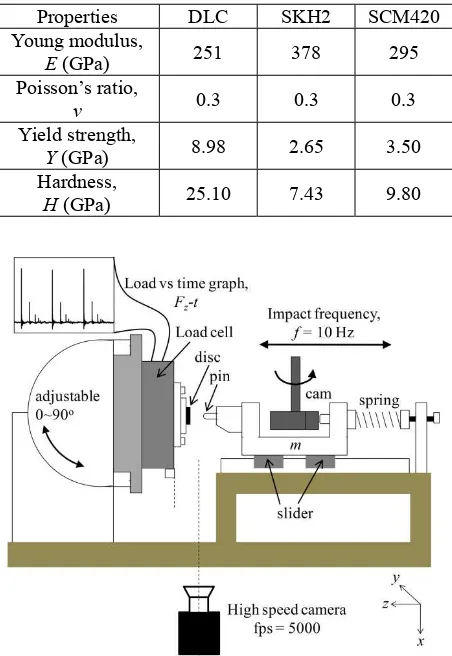
The disc specimens were coated with DLC using a PVD method. The SKH2 disc was used as a substrate. The influence of impactor mass was also considered, where impactors were 115.4 g and 171.5 g, respectively. The material properties are listed in Table 1. Prior to the impact test, both disc and pin were cleaned using acetone in an ultrasonic bath. The impact test was performed using a self-developed impact tester, as shown in Fig. 1, where a DLC coated disc was repeatedly impacted by a SCM420 pin, at 400 impact cycles, at room temperature. The diameter of disc and pin were 10 mm and 2 mm, respectively, as shown in Fig. 2. The 90o inclination of impact was run under lubricated conditions. Several different normal impact loads were applied to the DLC coated disc via a spring system and were observed by a load cell. The frequency of the impacts, f was selected at 10 Hz. The absorbed energy was determined using a high speed camera. As for the contact impulse and maximum normal impact load on the DLC coating, this can be obtained from the graph generated by a load cell. The contact impulse is determined from the area below the graph of normal impact load with time. In addition, 3D topography measurements were performed to obtain quantitative data on the residual impact crater volume/depth of DLC coating, using an Atomic Force Microscopy (AFM). The cross section of DLC coating on the SKH2 substrate was prepared using a Focused Ion Beam (FIB) and observed by Field Emission Scanning Electron Microscopy (FE-SEM). The worn surface of the SCM420 pin was analysed using Energy Dispersive X-ray Spectroscopy (EDS).
In this impact test, the maximum normal impact load is constant for each impact cycle, whilst the absorbed energy was obtained for one impact cycle. It is very difficult to get an accumulative absorbed energy for multi-impacts. Therefore, it is assumed that the residual impact crater radius, rr and depth, hr remain unaltered
under low impact cycles (in this study 400 cycles). As demonstrated in the experimental work11), a single loading and subsequent cyclic loadings formed an identical residual radii and depths of crater under the same contact loads. For that reason, the analytical solutions were performed for one impact cycle.
3. Theoretical background
The absorbed energy is calculated using the following equation:
1 2
1 2
2 1
v v v v m
Wa (1)
Where m is the impactor mass, v1 is the velocity before
impact, and v2 is the velocity after impact.
The change in the momentum of the pin, and the impulse, Fzdt acting on the load cell, are equal;
according to the law of conservation of momentum, if
other forces can be ignored1). This is expressed as:
v1 v2
m dtFz
(2)Because of the velocity after impact, v2 is in an opposite
direction to the velocity before impact, v1, the Eq.(2)
becomes:
v1 v2
m dtFz
(3)Table 1 Material properties of the DLC, SKH2 substrate and SCM420 pin
Properties DLC SKH2 SCM420 Young modulus,
E (GPa) 251 378 295
Poisson’s ratio,
v 0.3 0.3 0.3
Yield strength,
Y (GPa) 8.98 2.65 3.50
Hardness,
H (GPa) 25.10 7.43 9.80
Fig. 1 Schematic illustration of the repeated impact tester
The relationship between the maximum normal impact load, absorbed energy, and contact impulse, is given by substituting Eq.(3) into (1), which yields:
v v
Fdt
v v
F tWa12 1 2
z 12 1 2 z (4)In the case of the normal impact, where a target deforms plastically, most of the initial kinetic energy, W1
is dissipated as plastic work, Wp in the target, with small
amounts being restored by elastic forces to the kinetic energy of the rebounding projectile, W2. Besides, one
possible source of this energy loss appears to lie in the dissipation of energy in the specimen, in the form of elastic vibrations, Wv occasioned by the transient nature
of the collision12). An expression of these energies can be shown as follows:
p
The estimation of the Wv was theoretically derived
by Hutchings, I.M.13). It is assumed that the contact pressure, acting over the area of contact, is constant, then:
density and Young modulus, respectively. Fz is the
maximum normal impact load, e is the coefficient of restitution, and t is the loading time, obtained from the graph of load-time relationships. is a dimensionless quantity dependent only on Poisson’s ratio12). For v = 0.25, = 0.537 and for v = 0.3, = 0.415. The variation of with e has been computed numerically by Hutchings, I.M.13). The reason why the material properties of the substrate were used in the theoretical analysis, instead of the film properties, will be described later in this paper (Section 4.1).
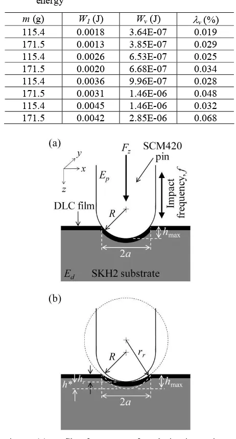
The elastic vibrational energy is calculated from Eq.(7). Table 2, presents the fraction v of the initial
kinetic energy, dissipated in the form of elastic vibrations and is typically only a few per cent, approximately 0.02% - 0.07% of the W1. For that reason,
it is proposed that the dissipation of energy, in the form of elastic vibrations, becomes negligible and the loss of energy is mainly from the Wp.
The process of impact may be divided into three parts11). (i) When the impactor, with a radius of R, first strikes the flat surface, an elastic deformation takes place until the mean pressure developed is sufficient to cause plastic deformation of the flat surface. (ii) Plastic
deformation of the flat surface now occurs accompanied by a building up of further elastic stresses in both the impactor and the flat surface. (iii) There is now a release of elastic stresses in the impactor and the flat surface surrounding the impaction, as a result of which rebound occurs as shown in Fig. 3, where the rr> R.
Table 2 Fraction of vibration energy to the initial kinetic energy
Fig. 3 (a) Profile of contact surface during impacting at the maximum normal impact load (b) The remaining permanent impact crater at the end of impact
A subsequent loading to hmax will obey Hertz
solution for a perfect spherical shape, thus14)
d
pin, respectively.
From geometrical considerations, the remaining permanent impact crater volume11) is:
r
The work done as plastic deformation energy, Wp is
defined as the total energy under elastic, We to
elastic-plastic deformation, Wep and the energy of
rebound, Wr :
The mean contact pressure under elastic, pe,
elastic-plastic, pep are given by Johnson, K.L.14). The
initial mean contact pressure, under rebound conditions, pr is assumed to be the same as the mean contact
pressure at the end of the loading process, pep, thus:
R
Where Y, is the yield strength of the substrate
The impact crater volume when elastic yield occurs, V’ and under elastic-plastic, Vep are calculated as
By combining Eqs.(12) – (25)
ep
4. Results and discussion
4.1. Morphology observation of the impacted DLC coating
In this study, the DLC film is very thin and the ratio of film thickness to pin radius, hc/R is approximately 0.003.
From the finite element analysis by Michler, J. and
Blank, E.8),thin films with a ratio of hc/R < 0.01 have no
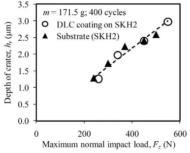
effect on the load bearing capacity of the surface. Besides, the deformation of an elastic-perfect plastic substrate, is not supposed to be altered by the presence of a thin film, which itself, simply follows the deformation of the substrate at the interface. This is in accordance with this study, where the residual depth of the impact crater, with or without a DLC coating, shares the same line and formed a good relationship with the maximum normal impact load, as shown in Fig. 4. Additionally, the residual depth of impaction is less than the film thickness, as shown in Fig. 5. As stated by Begley, M.R. et al.9), a thin film does not play a significant role, when the depth of the affected area is less than approximately five times the thickness of the film. The strain in the film is governed by the surface strain in the substrate. Therefore, in this study, the material properties of the film could be ignored (i.e., Efilm= Esubstrate = Ed) in order to calculate the theoretical
values.
Fig. 4 The residual depth of crater, with or without DLC coating on the SKH2 substrate after impact at 400 cycles
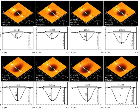
At the higher maximum normal impact load, where the light impactor was used, it obviously shows that microslip has occurred. The pin, where attached to the light impactor, has shifted tangentially by a small amount, during impact (indicated by the larger ax as compared to
ay, as shown in Fig. 6). This tangential movement is
usually caused by an elastic deformation of the supporting structures15).
A cross-sectional observation, of the impacted DLC coating at the higher normal impact load (Fig. 7), reveals that no cracks or film exfoliation has occurred within the DLC film. The relative ratio of the difference in non-impacted and impacted thicknesses of DLC film to its original thickness, ∆hc/hc, is approximately 1/50, and
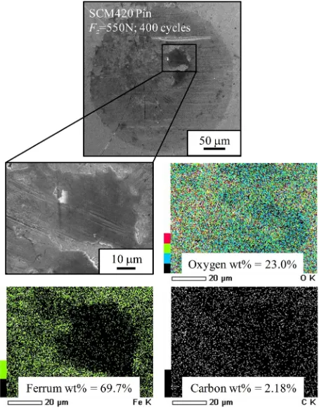
carbon element (C) indicates no transfer layer from the DLC coating to the pin is observed. These results apparently show that the residual impact crater volume and its depth are not due to real material loss, but mainly due to plastic deformation.
4.2. Experimental relationship between the residual impact crater volume/depth with a maximum normal impact load, absorbed energy, and the contact impulse
Fig. 9 shows how the residual impact crater volume/depth of DLC coating, varies with maximum normal impact load, absorbed energy, and the contact impulse. The implication of the contact impulse to the residual impact crater volume/depth of DLC coating is apparently not very good. Two different curves are clearly illustrated. At first thought, this poor relationship might be dependent on impactor mass. However, a fairly good agreement is obtained from the responses of maximum normal impact load and absorbed energy regardless of impactor mass. Thus, Eq.(4) suggests that this discrepancy is due to the total difference of impact velocity, (v1 - v2). Therefore, it is directly independent of
the impactor mass.
From the regression analysis, using the least squares curve fitting method, the experimental relationship between the residual impact crater volume/depth of DLC coating and the maximum normal impact load, as well as the absorbed energy, are as follows:
3694 . 0 0061 .
0
z
r F
h (27)
668 . 0
458 .
121 a
r W
h (28)
1813 . 2
1413 .
0 z
r F
V (29)
219 . 1 8
10 1455 .
1 a
r W
V (30)
Although the plotted graph of residual depth of crater versus maximum normal impact load shows the best curve fitting, which is indicated by the highest chi-squared value, R2; a cluster of data points, on its residual impact crater volume, can also be seen at a higher maximum normal impact load. This is due to the microslip effect, where the light impactor was used, as described previously. Consequently, the residual impact crater volume is larger than it should be.
Fig. 6 The biggest difference between ax and ay is
caused by the effects of microslip
Fig. 7 FE-SEM cross-sectional view of the FIB-milled DLC coating on the SKH2 substrate after impact, with (a) non-impacted film thickness and (b) impacted film thickness
4.3. Comparison of experimental results with analytical solutions of residual impact crater volume/depth
For the impact, with maximum normal impact load Fz, one can determine hrand a from Eqs.(12) and (13)
and then use Eqs.(15) and (26) to calculate the Vrand
Wp. This Wp can be expressed from Eq.(6) as an
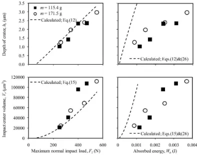
absorbed energy, where the elastic vibrations become negligible. These calculated values are plotted in the same axis of the experimental graphs of residual impact crater volume/depth of DLC coating, against maximum normal impact load and absorbed energy.
A comparison of the calculated and experimental results is shown in Fig. 10. It is seen that the agreement between the residual impact crater volume/depth of DLC coating against maximum normal impact load, is reasonably good. However, the agreement for the
absorbed energy is poor, where the experimental values are approximately 3 times larger than the calculated values. From this comparison, and based on the highest chi-squared value, R2 from the experimental relationship, it can be concluded that the most important factor affecting the residual impact crater volume/depth of DLC coating, is the maximum normal impact load.
Fig. 8 EDS colour profile analysis of the worn surface of the SCM420 pin, after impact with the DLC coated disc
5. Conclusions
The impact test was performed to evaluate the significance of maximum normal impact load, absorbed energy, and contact impulse, on the residual impact crater volume/depth of DLC coating. The following main results were obtained:
(i) Residual impact crater volume/depth of DLC coating is not in a good relationship with the contact impulse.
(ii) The residual impact crater volume/depth of DLC coating is dependent on maximum normal impact load and absorbed energy.
Fig. 9 Experimental relationship between the residual impact crater volume/depth of DLC coating and the maximum normal impact load, absorbed energy, as well as the contact impulse. The dashed line indicates the best fitting curve
6. Acknowledgement
The author, Mohd Fadzli Bin Abdollah gratefully acknowledges the scholarship from Universiti Teknikal Malaysia Melaka (UTeM) for his doctoral study.
7. References
[1] Fujii, Y. and Fujimoto, H., “Design Note: Proposal for an Impulse Response Evaluation Method for Force Transducers,” Meas. Sci. Technol, 10, 1999, 31-33.
[2] Zhu, X., Dou, H., Ban, Z., Liu, Y. and He, J., “Repeated Impact Test for Characterization of Hard Coatings,” Surface and Coatings Technology, 201, 2007, 5493-5497.
[3] Robinson, P. and Davies, G. A. O., “Impactor Mass and Specimen Geometry Effects in Low Velocity Impact of Laminated Composites,” International Journal of Impact Engineering, 12, 2, 1991, 189-207.
[4] Lawes, S. D. A., Hainsworth, S. V. and Fitzpatrick, M. E., “Impact Wear Testing of Diamond-Like Carbon Films for Engine Valve-Tappet Surfaces,” Wear, 268, 2010, 1303-1308.
[5] Ledrappier, F., Langlade, C., Gachon, Y. and Vannes, B., “Blistering and Spalling of Thin Hard Coatings Submitted to Repeated Impacts,” Surface and Coatings Technology, 202, 2008, 1789-1796. [6] Zanoria, E. S. and Seitzman, L. E.,
“Characterization of Thin Metallurgical Coating Systems by Repetitive Inclined Impact Test in Dry Condition,” Surface and Coatings Technology, 182, 2004, 161-170.
[7] Batisca, J. C. A., Godoy, C. and Matthews, A., “Impact Testing of Duplex and Non-Duplex (Ti,
Al)N and Cr-N PVD Coatings,” Surface and Coatings Technology, 163-164, 2003, 353-361. [8] Michler, J. and Blank, E., “Analysis of Coating
Fracture and Substrate Plasticity Induced by Spherical Indentors: Diamond and Diamond-Like Carbon Layers on Steel Substrates,” Thin Solid Films, 381, 2001, 119-134.
[9] Begley, M. R., Evans, A. G. and Hutchinson, J. W., “Spherical Impression of Thin Elastic Films on Elastic-Plastic Substrates,” International Journal of Solids and Structures, 36, 1999, 2773-2788. [10] Knotek, O., Bosserhoff, B. and Schrey, A., “A New
Technique for Testing the Impact Load of Thin Films: The Coating Impact Test,” Surface and Coatings Technology, 54-55, 1992, 102-107. [11] Tabor, D., “A Simple Theory of Static and
Dynamic Hardness,” Proceedings of the Royal Society A: Mathematical, Physical & Engineering Sciences, 192, 1948, 247-274.
[12] Hunter, S. C., “Energy Absorbed by Elastic Waves during Impact,” Journal of Mechanics and Physics of Solids, 5, 1957, 162-171.
[13] Hutchings, I. M., “Energy Absorbed by Elastic Waves during Plastic Impact,” Journal of Physics D: Applied Physics, 12, 1979, 1819-1824.
[14] Johnson, K. L., “Contact Mechanics,” Cambridge University Press, Cambridge, 1985, 171-179. [15] Stachowiak, G. W. and Batchelor, A. W.,
“Engineering Tribology,” Elsevier Butterworth-Heinemann, USA, 2005, 644.