PREDICTION OF HELICAL GEAR LIFE USING WEAR DEBRIS ANALYSIS
MOHD FIRDAUS BIN JAMALUDIN
PREDICTION OF HELICAL GEAR LIFE USING WEAR DEBRIS ANALYSIS
MOHD FIRDAUS BIN JAMALUDIN
This report is submitted in
Fulfillment of the requirements for the degree of Bachelor Degree of Mechanical Engineering (Thermal Fluid )
Fakulti Kejuruteraan Mekanikal Universiti Teknikal Malaysia Melaka
ii
DECLARATION
“I acknowledge the work is my own work except for quotations and a summary and the accompanying expression which have been duly recognized”
Signature :….………...
iii
ACKNOWLEDGEMENT
iv
ABSTRAK
v
ABSTRACT
vi
TABLE OF CONTENT
CHAPTER CONTENT PAGE
DECLARATION i
ACKNOWLEDGEMENT iii
ABSTRAK iv
ABSTRACT v
TABLE OF CONTENT vi
LIST OF TABLE viii
LIST OF FIGURE x
LIST OF SYMBOL xii
LIST OF EQUATION xiii
CHAPTER I INTRODUCTION
1.1Research Background 1
1.2 Research Overview 2
1.3 Problem Statement 3
1.4 List of Objective 3
1.5 Scope of Project 3
CHAPTER II LITERATURE REVIEW
2.1 Introduction 4
2.2 Typical Defect in gear 5
2.3 Types of Gear Damage 6
vii
2.3.2 Scoring 9
2.3.2.1 Initial Scoring 10
2.3.2.2 Moderate scoring 10
2.3.2.3 Destructive Scoring 10
2.3.3 Scuffing 12
2.3.4 Wear 15
2.4 Wear Mechanism 16
2.5 Stage of Wear 17
2.6 Wear Classification due to Mechanism 18
2.7 Type of Wear 19
2.8 Wear Due to Mechanical Process 20
2.8.1 Abrasive Wear 20
2.8.1.1 Cutting Abrasive wears 22 2.8.1.2 Fracture abrasive wear 22 2.8.2.3 Fatigue abrasive wear 22 2.8.2.4 Grain Pull Out abrasive wears 22
2.8.2 Adhesive Wear 23
2.8.3 Fatigue Wear 24
2.8.4 Erosion Wear 26
2.8.5 Cavitation Wear 27
2.8.6 Fretting Wear 29
2.9 Wear Debris Analysis 30
CHAPTER III METHODOLOGY 31
3.1Introduction 31
3.2 Flow Chart 32
3.3 Theoretical life calculation for gear 33 3.4 Experimental using gear test rig 36
3.4.1 Gear Test Rig Preparation 36
3.4.2 Gear Test Rig Specification 38
3.4.3 Gear Specification 39
viii
3.5.1 Procedure of experiment 41
3.6Gear Test Rig Operation Procedure 42
3.7Sampling Procedure 46
3.8Visual Inspection Procedure 47
3.9Wear Debris Classification 48
CHAPTER IV RESULTS AND DISCUSSION
4.1 Introduction 48
4.2Result 50
4.2.1 Physical inspection 51
4.2.2 Debris Image result 57
4.2.3 Temperature measurement result 62
4.3 Theoretical result 63
4.3.1 Sample Calculation (BS ISO 6336-2) 63 4.3.2 Stress and Force Analysis 74
4.3 Discussion 81
4.3.1 Discussion on experimental results 81 4.3.2 Discussion on the theoretical results. 83
CHAPTER V CONCLUSION
ix
LIST OF TABLE
BIL TITLE PAGE
2.1 Pitting Damage 8
2.2 Type of Scoring Damage 11
2.3 Type of Scuffing Damage 14
3.1 Gear specification 38
4.1 Gear Surface from Visual Inspection during Experiment 51
4.2 Debris Image Result Using Microscope 57
4.3 Tabulate Temperature for Oil Gear during Operation 62
4.4 Variable Result from Calculation 69
4.5 KA
,Kv,KH and KH For Helical And Spur Gear 71
4.6 Contact Stress 72
x
LIST OF FIGURE
BIL TITLE PAGE
2.1 Initial and Destructive Pitting 11
2.2 Abrasive Wear Mechanism 20
2.3 Moderate Adhesive Wear 24
2.4 Fatigue Wear Mechanism 25
2.5 Cavitation Wear 27
2.6 Fretting Wear 29
3.1 Flow Chart 31
3.2 Gear Test Rig Detail Drawing 36
3.3 Gear Test rig (Frame) 37
3.4 Drawing of Gear 38
3.5 Gear Test Rig Machine 41
3.6 Gear test rig 42
3.7 Clutch Load 42
3.8 Drive gear and stopper 43
3.9 Load lever and weight 43
3.10 Tachometer 55
3.11 Oil sampling apparatus 56
4.1 Graph of temperature, (°c) vs. Time (hour) 62
4.2 Gear Test rig 74
4.3 Gear test rig schematic diagram 74
xi
4.5 Free body Diagram 75
4.6 Reaction force at testing gear 76
xii
LIST OF SYMBOL
HO
= Nominal contact stress
KA = Application factor
KHα = Transverse load factor for contact stress KHβ = Face load factor contact stress
KV = Dynamic factor
ZB = Pinion single pair tooth contact factor
ZL = Lubrication factor
ZNT = Life factor for contact stress
ZR = Roughness factor
ZV = Velocity factor
ZW = Working hardening factor
ZX = Size factor
SHmin = Safety factor
εβ = Overlapping ratio
σH = Contact stresses
xiii
LIST OF EQUATION
NAME OF EQUATION LIST OF EQUATION
1
CHAPTER I
INTRODUCTION
1.1Research Background
2
1.2 Research Overview
The project main objective is to predict onset of failure of helical gear life using wear debris analysis. The research about how to predict helical gear life using identified method. The method could involve in this research should be theoretical and experimental method. Then, the comparison about the result of both methods should give the efficiency view.
By using wear debris that obtains from the test, it used to analyze and then come out with several data and result to predict the helical gear life. Regarding wear debris obtain, it could determine the mechanism of wear. In this research also contain a study about the failure onset helical gear during the test. Then, the finding and understanding about of the helical gear failure will be cover during the research. Then, the observation on the behavior of the helical gear wear mechanism is a part of research activities. From there, several types of wear mechanism should be defined based on the wear debris obtains. The studies about type of wear mechanism also cover to determine helical gear life.
3
1.3 Problem Statement
Gear is an important component in a machine or equipment. The rubbing and rolling action in the gear meshing will normally generate wear debris. However, the increase in abnormal loading due to misalignment will increase the risk of unpredicted gear failures. These failures will result in the unexpected lost of production and increase of maintenance cost. Hence, it is recommended to predict the onset of failure of the gear to allow replacement at the right time before catastrophic failure occurs.
1.4 List of Objectives
To study the phenomena and mechanism wear of gear.
To predict the onset of failure of helical gear using Wear Debris Analysis technique.
1.5 Scopes of Project
Laboratory gear test rig
Study on the helical gear failure.
4
CHAPTER II
LITERATURE REVIEW
2.0Literature Review
2.1 Introduction
Nowadays, research and development in the manufacturing process were rapidly improved day by day. The improvement of research and development in manufacturing process give to many advantages in manufacturing industry especially. Research and development in the maintenance sector improved a lot in manufacturing industry. Maintenance research and development has been looking as important part as the problem needs to solve in manufacturing or production process. The problem occurs will cause waste in the industry especially will affect to the core of business itself.
5
2.2Typical defect in Gear
The majority of problems associated with things as well as moving component bearings begin because local stage flaws in touch areas in between getting in touch with physiques. Equipment problems tend to be started within the teeth meshing area as well as showing problems within the moving get in touch with areas. Defect of gear possible to identify as well as identify could be categorized within 3 classes regarding their own cause:
1. Installation defect.
2. Defects develop in operation.
3. Defect on the neighboring element which produce dynamic load on bearings and gears.
Crack and also spalls will be the many radical problems inside the stand. Spalling is actually brought on by the higher, nearby, get in touch with tension levels local beneath the actual get in touch with area. Typically any split will be trigger info substance introduction positioned through this zoom regarding large tensions. The particular split moves along as a result of duplicated cyclical packing in the course of equipment functioning. With a specific period the particular split actually reaches a crucial dimension as well as the progress grows to be unstable.In the unstable phase the crack rapidly grows and eventually reaches the surface, and a piece of material comes loose, creating a spall. All defects in table modify the characteristic vibration signature. One of the main tasks of machine monitoring is to identify and localize these defects from measured signatures. There have several typical defects in gear such as:
1. Localized surface damage 2. Wear or inadequate lubrication 3. Tooth root cracks, missing tooth 4. Pitch error
6
2.3Type of Gear Damage
Gearing is a crucial part of several components in many machines. The particular extensive application regarding gears in the machine and also mechanism, which includes high speed and also heavy duty to operate with lower temperatures and also high temperature and also beneath exposure to any excessive load cause damage and also catastrophic failure with their tooth result in simply by transmitting load, rotation speed or perhaps thermal therapy along with manufacture and operating condition .The result of gear damage majority associated with typical of gear damage. [A. M. Goman et.al., 2000]
Since there is increasing engagement in examine regarding gear damage inside manufacturing process, the effect coming from gear damage obtain particle or perhaps wear debris which will be found in examine the wear phenomena and also the mechanism of gear. Then, through the process operation the damage of gear were identified into several types.
The type of damage classification is due to the gears in the machine and mechanism, including high speed and applying load on the system .The main damage of gear is state bellow [A. Miltenovic, 2011]
1. Pitting 2. Scoring 3. Scuffing 4. Wear
7
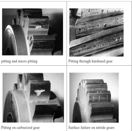
2.3.1 Pitting and Micro pitting.
Pitting or macro pitting can be surface damage through cyclic contact to strain transmit by having a lubrication that may be throughout as well as at the elastohydrodynamic plan. Pitting is just about the most common reasons behind gear failure. Then, it also influences antifriction bearings, cams, and also other appliance factors through which materials experience rolling as well as sliding off the contact under excessive load. Pitting is definitely the result of repeated contact stresses that cause gear surface and also subsurface fatigue and detachment with a material fragment from gear tooth surface types which will surface types undergo rolling or sliding under excessive load [Hermann Siebert, Michael Hochman, 2012].
Pitting happens when exhaustion crack tends to be initiated about the tooth surface or simply below the surface. Usually pits are caused by surface crack brought on by metal to metal get in touch with of asperities or even defect because of low lubrication layer on the surface that cause the lubricant viscosity was reduced through the operation. High speed gears along with smooth area and large lubricant layer may encounter pitting because of subsurface break.
Pits tend to be formed whenever this breakthrough with the tooth surface and since the particle obtain. Pitting may also cause through contamination associated with lubricant. These contaminants create surface stress focus points which reduce the lubrication film thickness to create pitting [K. Gopinath, 2012]. Table below shows the picture types of pitting damage on gear through the operation. Those types of pitting damage are:
8
Table 2.1: Pitting Damage (Source: Dr. Ing. Klaus Michaelis, 2011)
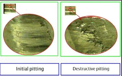
A huge pressure in surface does not lead to the sudden failure on gear surfaces, but at the time, small holes (pits) emerge inside shape involving shell in tooth flank. Pit peak always points inside sliding route. This destruction occurs by having a cyclic fatigue on account of repeated elastic and plastic deformations in the surface. The holes occur only from a sufficiently numerous overruling. Only when initial pitting is present, the situation is just not dangerous but if destructive pitting destroys occurs on the flank along with cause of failure due to noise along with fatigue.
pitting and micro pitting Pitting through hardened gear
9
Figure 2.1: Initial and Destructive Pitting (Source: A. Miltenovic, 2011).
The Figure 2.2, describes the condition of the gear. From the figure the initial
pitting is not dangerous. Since the initial pitting occurs, it will generate destructive
pitting on the gear surface. Destructive pitting Destructive pitting destroys the flank and
causes failure due to noise and fatigue.
2.3.2 Scoring
10
Scoring damage mark is stick to the course of motion on the bearing surface. The scoring damage marks start the contact surface where the dirt particle connects the motion layer and form a consistent mark around the end with the gear surface area, the trailing edge around the right with the pad inside the Photograph, or stop having an embedded particle. Scoring is among abrasive wear, adhesive wear gives discontinuous tears as opposed to clear uninterrupted scores.
2.3.2.1 Initial scoring
Initial scoring occurs in the high places left through previous machining. Lubrication fails at these types of spots results in initial rating or scuffing because shown within table 2.2. Once these types of high places are eliminated, the stress boils down as force is distributed on the larger region. The scoring will stop when the load, pace and heat of essential oil remain the same or decreased. Initial rating is non-progressive and it has corrective action related to it [K.Gopinath, 2011].
2.3.2.2 Moderate scoring
Moderate scoring occurs if the Scoring progresses at tolerable rate. After initial scoring if the load, speed or oil temperature increases, the scoring will spread over to a larger area. It is shown in table:
2.3.2.3 Destructive scoring