DEVELOPMENT OF PC BASED INTERFACE CARD FOR DC DRIVE SYSTEM
SHARIMAN BIN IBRAHIM
“I hereby declared that this report is a result of my own work except for the excerpts that have been cited clearly in the references.”
Signature : ………..
Name : ………..
DEDICATION
To my beloved mother Shaharom bt Aziz and to my supervisor Pn Intan Azmira bt Wan abdul Razak and to all my friends for all their support throughout my studies. Last but not
DEVELOPMENT OF PC BASED INTERFACE CARD FOR DC MOTOR DRIVE SYSTEM
SHARIMAN BIN IBRAHIM
This Report is submitted in Partial of Requirements for the Degree of Bachelor in Electrical Engineering (Mechatronic)
Fakulti Kejuruteraan Elektrik Universiti Teknikal Malaysia Melaka
“I hereby declared that I have read through this report and found that it has comply the partial fulfillment for awarding the degree of Bachelor of Electrical Engineering
(Mechatronic).”
Signature : ………..
Supervisor Name : ………..
ABSTRACT
ABSTRAK
ACKNOWLEDGEMENTS
Alhamdulillah, the highest thanks to God because with His Willingness I possible to complete the final year project in time.
I would like to express my gratitude to my dedicated supervisor, Pn Intan Azmira Bt Wan Abdul Razak for guiding this project with clarity and that priceless gift of getting things done by sharing her valueable ideas as well as her knowledge.
I also like to thank to all UTeM lecturers and electrical technicians whom had helped directly or indirectly in what so ever manner thus making this project a reality.
Not forgotten are my best colleagues for their openhandedly and kindly guided, assisted, supported, and encouraged me to make this project successful. My heartfelt thanks to my dearest family which always support and pray on me throughout this project. Their blessing gave me the high-spirit and strength to face any problem occurred and to overcome them rightly.
CONTENTS
CHAPTER TOPIC PAGE
TITLE i
DECLARATION ii - iii
DEDICATION iv
ACKNOWLEDGEMEN v
ABSTRACT vi
ABSTRAK vii
CONTENTS viii
LIST OF FIGURE xii -
xiii
LIST OF TABLE xiv
1.0 INTRODUCTION
1.1 Background 1
1.2 DC motor 1 - 2
1.3 Objective 2
1.4 Scope 2
1.5 Thesis Outline 3
2.0 LITERATURE REVIEW
2.1 DC motor characteristic 4
2.2 PWM using PIC 16F873 Microcontroller 5-7 2.3 A3953SB Full Bridge Integrated in DC
Motor Mode 8 - 9
Speed Control 9-11
2.5 RS-232 Serial Port 11 - 13
3.0 PROJECT DEVELOPMENT
3.1 Background 14-15
3.2 Hardware Design 16-17
3.2.1 Control Voltage Input 18
3.2.2 Motor Drive 19
3.2.3 LED Display 20
3.2.4 PWM Calculation 20-22
3.3 Software Development 22-25
3.4 Operation of the System 26-27
3.4.1 MicroC Process Explaination 27 - 30 3.4.2 Initialization Process 30-34
4
4..00 RERESSUULLTT AANNDD DDIISSCCUUSSSSIIOONN 4
4..11 InInttrroodduuccttiioonn 3535 4
4..22 Analysis Procedure 3535 4
4..33 DC Motor Output Performances And
Analysis Results 3636-- 3377 4
4..44 Discussion 3737--3388
5
5..00 COCONNCCLLUUSSIIOONN AANNDD RREECCOOMMMMEENNDDAATTIIOONN 3939 5
5..11 CoConncclluussiioonn 3939 5
5..22 ReReccoommmmeennddaattiioonn 4040
6
6..00 REREFFEERREENNCCEESS 4141--4422
A
LIST OF FIGURE
No Title Page
2.1 A Basic DC Motor. 4
2.2 Example of PWM Duty Cycle Signals 5
2.3 PWM Frequency Configuration for PIC 16F87X Series 6
2.4 PIC 16F873 Pins Configuration 6
2.5 A3953 Full-Bridge Driver Pins Configuration 9
2.6 DB9 Male Configuration 11
2.7 DB9 Female Configuration 12
3.1 Design Flow for PC-Based Interface Card System 14
3.2 Complete Project Flow 15
3.3 PIC 16F873 Pin Connection Circuit 17
3.4 A3953SB Full-Bridge Driver Circuit 17
3.5 (a) CW Mode and (b) CCW Mode 24
3.6 Design Flow for the MPLAB 25
3.7 Block Diagram for the System 26
4.1 Graph Voltage Output versus Duty Cycle for CW
Operation 36
4.2 Graph Voltage Output versus Duty Cycle for CCW
LIST OF TABLE
No Title Page
2.1 D Type 9 Pin and D Type 25 Pin Connectors 13
3.1 Motor Control Condition 23
3.2 Truth Table for PWM 27
4.1 Value of Output Voltage, Vo Corresponding to
CHAPTER 1
INTRODUCTION
1.1 Background
This chapter explains the operation of a direct current (DC) motor and its implementation to the industry. The development of DC motor speed control also discusses and briefly explains in this chapter. This chapter also explains the overview of project objectives, project scopes and thesis outline.
1.2 DC Motor
DC motors are commonly and widely used in many industrial applications as the primary power source. Basically, in any DC motor, operation is based on simple electromagnetism. A current-carrying conductor generates a magnetic field; when this is then placed in an external magnetic field. A small DC motor generates torque by creating an interaction between a fixed and rotating magnet field. Generally, the rotational speed of a DC motor is proportional to the voltage applied to it, and the torque is proportional to the current. Speed control can be achieved by variable battery tapping, variable supply voltage, resistors or electronic controls.
scheme or algorithm. The purpose of a motor speed controller is to take a signal representing the demanded speed, and to drive a motor at that speed. The controller may or may not actually measure the speed of the motor. The speed of a DC motor is directly proportional to the supply voltage, so if we reduce the supply voltage from 12 Volts to 6 Volts, the motor will run at half the speed.
The greatest advantage of DC motors may be speed control. Since speed is directly proportional to armature voltage and inversely proportional to the magnetic flux produced by the poles, adjusting the armature voltage and the field current will change the rotor speed. Extremely good speed control from standstill to full speed, and consistent torque for DC motor can be obtained by varying the generator and motor field current.
1.3 Objective
The objective of this project is to develop PC-based interface drive circuit for DC motor. The DC motor drive system has to communicate with the PC in serial connection and user will be able to control the speed of the DC motor.
1.4 Scope
1.5 Thesis Outline
Chapter 1 explains the operation of a direct current (DC) motor and its implementation to the industry and the development of DC motor speed control. The overview of project objectives and project scopes also discuss in this chapter.
Chapter 2 focuses on the literature review that related to this project. The DC motor characteristic, Pulse Width Modulation, PIC 16F873 microcontroller, A3953 Full-Bridge driver and RS-232 serial port are discuss in this chapter.
Chapter 3 discusses about the methodologies of computer-based interface card system design for DC motor drive including PIC microcontroller interface, PC-based interface and also PWM calculation. This chapter also explains the software development and also the operation of the Computer-based Interface Card System for DC motor drive.
Chapter 4 explains and discusses all the results obtained and the analysis of the project. All discussions are concentrating on the result and performance of the DC motor output.
CHAPTER 2
LITERATURE REVIEW
In order to perform this project, literature review have been made from various sources likewise journal, books and other references such as article. In simple term, the reference sources emphasize on few aspects and the important aspect is the how to construct the interface card for the DC motor drive. This chapter will describe about DC motor, PWM duty cycle, PIC16F873, A3953 full bridge driver, RS-232 serial port, and bidirectional dc motor speed control.
2.1 DC Motor Characteristic
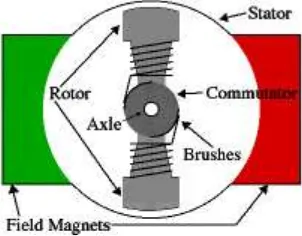
[image:16.612.249.400.549.667.2]Basically, in any DC motor, operation is based on simple electromagnetism. A current-carrying conductor generates a magnetic field then placed in an external magnetic field. A small DC motor generates torque by creating an interaction between a fixed and rotating magnet field. Every DC motor has six basic parts which are axle, rotor (armature), stator, commutator, field magnets, and brushes.
DC motors are divided into three classes, designated according to the method of connecting the armature and the field windings as shunt-series and compound wound. When current passes through the coil wound around a soft iron core the side of the positive pole is acted upon by an upwards force, while the other side is acted upon by a downward force.
The main purpose of a DC motor speed controller is to take a signal representing the demanded speed, and to drive the motor at that speed. The controller may or may not actually measure the speed of the motor. If it does, it is called a Feedback Speed Controller or Closed Loop Speed Controller, if not it is called an Open Loop Speed Controller. Feedback speed control is better, but the system is more complicated.
2.2 PWM using PIC 16F873 Microcontroller
Figure 2.2: Example of PWM Duty Cycle Signals
Pulse Width Modulation control works by switching the power supplied to the motor on and off very rapidly. The DC voltage is converted to a square-wave signal. By adjusting the duty cycle of the signal (modulating the width of the pulse, hence the 'PWM') i.e., the time fraction it is "on", the average power can be varied, and hence the motor speed.
[image:18.612.133.550.481.539.2]The software MPLAB is used as coding compiler for the microcontroller. PIC 16F873 has 28 pins. The important pins that use to generate Pulse Width Modulation signal is CCP2 pin and named as PWM1 output.
Figure 2.4: PIC 16F873 Pins Configuration
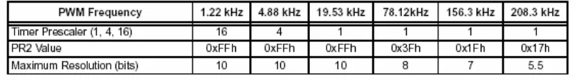
In Pulse Width Modulation mode, the CCP1 pin produces up to a 10-bit resolution PWM output. Since the CCP1 pin is multiplexed with the PORTC data latch, the TRISC<2> bit must be cleared to make the CCP1 pin an output. The Pulse Width Modulation calculation is focus on period and duty cycle. The PWM calculation is shown in Chapter 3.
The PWM period is specified by writing to the PR2 register. The PWM period can be calculated using the following formula:
PWM period = [(PR2) + 1] • 4 • TOSC • (TMR2 prescale value) PWM frequency is defined as 1 / [PWM period].
i. TMR2 is cleared.
ii. The CCP1 pin is set (exception: if PWM duty cycle = 0%, the CCP1 pin will not be set).
iii. The PWM duty cycle is latched from CCPR1L into CCPR1H.
2.3 A3953SB Full Bridge Integrated in DC Motor Mode
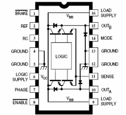
A3953SB Full-Bridge driver is an Integrated Circuit (IC) that is design for bidirectional Pulse Width Modulation (PWM) current control of inductive loads. The driver is capable of continuous output currents to ±1.3 A and operating voltages to 50 V. The fixed off-time pulse duration is set by user by choosing external RC timing network.
A3953SB Full-Bridge driver has 4 main pin for driving the motor. These 4 pins are ENABLE, BRAKE, MODE and PHASE. Each pin has it own function. ENABLE pin must be in active low condition for driving the motor. It is because, with the ENABLE input held low, the PHASE input controls load current polarity by selecting the appropriate source and sink driver pair. If the ENABLE pin is in high condition, all output drivers are disabled. A sleep mode is provided to reduce power consumption. The MODE pin determines whether the PWM current-control circuitry operates in a fast current-decay mode or in slow current-decay mode.
For PWM purpose, the PHASE and ENABLE pins can be pulse width modulated to regulate load current. If the internal PWM current control is used, the comparators blanking function is active during phase and enable transitions. This eliminates false tripping of the over-current comparator caused by switching transients related to distributed capacitance in the load.
Figure 2.5: A3953 Full-Bridge Driver Pins Configuration
2.4 Dual Motor Bidirectional Electronic Speed Control
It describes an electronic speed control designed to drive two DC motors from a 7.2 Volt battery pack to be controlled by a commercial multi channel model radio control system. Conceived for a tank-like vehicle, one motor drives the left side wheels and the other motor drives the right side. There is a left-rightsteering input and a forward-backward throttle input, like would be used on a model car radio unit.
separate right and left throttle controls like a bulldozer, and it has been set up with direct wired controls instead of the radio link.
There are 5 major blocks which is:
1. Radio Interface. This block converts the pulse width modulated signal from a standard commercial radio control system into two analog control voltages.
2. Summing Section. This block converts the steering and throttle signals into control voltages for the right and left motor PWM generators.
3. PWM Generator. Converts the control voltages from the previous stage into Pulse Width Modulated digital signals suitable for driving the power sections. 4. Right and Left Power Sections. Contain the power FET‟s and associated gate
drivers to convert digital control signals into motor drive power. The power sections include the delay generation logic although it is shown separately.
5. Power Supplies. There is a 5 volt power supply for the electronics and an 18 volt power supply for the FET gate drives.
there are delay circuits put in between the logic level control signals and the actual FET Gate Drive IC inputs. These delays cause the gate turn on to be delayed a hundred nanoseconds or so and the gate turn off to be un-delayed.
Electric motors have a large amount of inductance so that when we can switch the current to them off rapidly (PWM) get a large voltage spike. This voltage spike will turn on the body diode in the opposite transistor while it bleeds off the energy stored in the motor‟s inductance. By virtue of the way we are handling the gate control on the FET‟s, we will help get rid of this energy by turning the opposite FET on when we turn one off. This technique is called synchronous rectification. Having exces- sively long delays on the gate control hinder this effect, making the body diodes carry more of the load.
After the delay circuits, it is necessary to turn logic level signals into FET gate drive signals. The large amount of capacitance seen looking into the gate on a large FET makes this problem. FET‟s require a fairly high gate voltage to turn on solidly, around 10 volts between the gate and source terminals for most of the large ones. System is designed to run on a 7.2 Volt battery pack. In system, there is a separate power supply to generate this higher voltage (about 18 volts) for the gate drives. If this system ran on about 12 volts or higher, we could use a simpler way to get that elevated voltage.
2.5 RS-232 Serial Port
Figure 2.6: DB9 Male Configuration
Figure 2.7: DB9 Female Configuration