Bhagu R. Chahar
Assistant Professor, Department of Civil Engineering, Indian Institute of Technology, New Delhi, India
Ghanshyam P. Vadodaria Research Scholar, Department of Civil Engineering, Indian Institute of Technology, New Delhi, India Proceedings of the Institution of
Civil Engineers Water Management 161 December 2008 Issue WM6 Pages 303–311
doi:10.1680/wama.2008.161.6.303 Paper 700071
Received 16/12/2007 Accepted 27/06/2008 Keywords:
drainage & irrigation/groundwater/ rehabilitation, reclamation & renovation
Steady subsurface drainage of homogeneous soils by ditches
B. R. Chahar
PhD,FISH,MIE,MIWRS, MIAHand G. P. Vadodaria
MEngSubsurface drainage of agricultural land is a method for improved production, a safeguard for sustainable investment in irrigation and a tool for conservation of land resources. An analytical solution for the problem of subsurface drainage of a ponded surface by an array of parallel ditches has been obtained using velocity hodograph and Schwarz–Christoffel transformation. The presented solution is applicable for the two-dimensional steady drainage from a horizontal ponded surface to an array of ditches in a homogeneous and isotropic porous medium. The solution includes equations for the quantity of drainage and the variation in seepage velocity. Thus the solution is a generalisation of Youngs solution. From this generalised solution, the particular solutions have also been deduced for different cases.
NOTATION
A, B, C dimensionless points on flow domain b width of ditch (m)
C1,C2 constants d depth of ditch (m) I1,I2,I3 dimensionless integrals
i imaginary number
k hydraulic conductivity (m/s)
q seepage discharge from one side of ditch per unit length (m2/s)
qD seepage discharge from one side of ditch below water surface (m2/s)
S spacing (half ) between ditches (m) t, dummy variables
u velocity of seeping water alongXaxis (m/s) V resultant velocity of seeping water (m/s) v velocity of seeping water alongY axis (m/s); W þi complex potential (m2/s)
X real axis of the complex plane (m) Y imaginary axis of the complex plane (m) y water depth in ditch (m)
y0 velocity reversal point along ditch water depth (m) Z XþiY complex plane variable (m)
,,, transformation or accessory parameters
complex variable in auxiliary plane
velocity potential (m2/s) stream function (m2/s)
1. INTRODUCTION
Irrigation is widely practiced in many parts of arid and semi-arid regions of the world to enhance agricultural production as
a result of the uncertainty in rain-fed agriculture.1Irrigation, however, has negative impacts such as waterlogging and increases in soil and groundwater salinity. In irrigated lands, depending on the extent and duration of waterlogging, the crop yield may reduce substantially or even reach zero.2Problems of waterlogging and soil salinisation are known to have developed in irrigated agriculture since the first human civilisation in Mesopotamia. The fall of this ancient civilization is attributed to both waterlogging and soil salinity.3The expansion of
waterlogging and soil salinity has been widely reported by many workers in India4and varies from 4.75 to 16 million ha and 3.3 to 10.9 million ha, respectively.5Waterlogging is also a problem experienced on cricket grounds, golf courses, race courses, parks and other amenities.
Problems such as water logging and soil salinity can be alleviated by application of a proper subsurface drainage design which helps in preventing the rise of the water table above a critical level.6Drainage maintains the productive capacity of soil by removing excess water, improving the soil moisture, improving the air circulation and reducing salt content and erosion. Ditches or tiles are used for the subsurface drainage. Compared with tiles, ditches do not require very accurate levelling, construction of gravel packs or geotextile wrapping, casing, anti-scaling, or anti-clogging measures.7Subsurface drainage has a long history: the oldest known systems date back some 9000 years in Mesopotamia. Subsurface drainage is a form of drainage that was widely introduced in Europe and North America in the 20th century. Among the developing countries, Egypt is the country with the largest area provided with subsurface drainage, about 2.5 million ha,8while countries such as Pakistan, China, Turkey and India are providing subsurface drainage to large tracts of their irrigated lands.9,10Out of the 1500 million ha of irrigated and rain-fed cropped lands of the world, only about 14% is provided with some form of drainage. The total area in need of artificial drainage can be roughly estimated to be 300 million ha, mainly in the arid and tropical humid zones of the developing countries.11Thus the analysis of subsurface drainage is important to ensure productivity of agricultural land and reclamation of land and for conservation of land resources.
porous medium with ponded water was analysed by Youngs29using conformal transformation, but the solution is restricted to a single ditch and is applicable only for the case of negligible width and zero ponded depth. In the present study, a general solution to the problem of drainage of a ponded field in a homogeneous and isotropic soil medium by an array of ditches is obtained using velocity hodograph and Schwarz–Christoffel conformal mapping12,30,31(refer to Appendix for details). The usefulness of conformal mapping in finding analytical solution to two-dimensional flow problems stems from the fact that solutions of Laplace’s equation remain solutions when subjected to conformal transformation. The solution of a two-dimensional
groundwater problem could be reduced to one seeking the solution of Laplace’s equation subject to certain boundary conditions within a regionRin theZplane. Unless the region Ris of a very simple shape, an analytical solution to Laplace’s equation is generally very difficult. By means of
conformal mapping, however, it is often possible to transform the regionRinto a simpler regionR1wherein Laplace’s equation can be solved subject to the transformed boundary conditions. Once the solution has been obtained in regionR1it can be carried back by the inverse transformation to the region Rof the original problem. Hence the crux of the problem is finding a series of transformations that will map a regionR conformally into a regionR1so thatR1will be of a simple shape, such as a rectangle or a circle. TheZ(physical) plane in the problem of subsurface drainage of a ponded area by an array of ditches is a polygon; its velocity hodogragh mapping is also a polygon. So both the planes have been mapped through Schwarz–Christoffel conformal transformation into an auxiliary plane to yield the desired analytical solution. The solution takes into account the effect of depth of water in ditches as well as width and spacing of ditches. The proposed solution includes expressions for the quantity of drainage and the velocity distribution of draining water.
2. ANALYTICAL SOLUTION
The physical domain of drainage from a ponded surface by an array of ditches of depthd(m) having spacing 2S(m) and water depthy(m) is shown in Fig. 1(a). The ditches partially penetrate into homogeneous and isotropic porous medium of infinite extent. Generally the ponded water is drained by surface
drainage. The remaining water is drained by subsurface drainage; therefore the depth of ponded water is assumed to be very small. It is also assumed that the flow is steady and satisfies Darcy’s law. In view of the significant length of the ditches, the flow in the porous medium can be considered two-dimensional in the vertical plane, thus the solution of a two-dimensional Laplace equation with boundary conditions answers this problem. Owing to vertical symmetry, the solution for the half domain (ABCDEE0F) is sought. Let complex potential W ¼þi , where¼velocity potential (m2/s) which is equal to the negative of hydraulic conductivityK(m/s) multiplied by the headh(m) and ¼stream function (m2/s) which is constant along streamlines. If the physical plane is defined as Z¼XþiY then Darcy’s law yieldsu¼@=@X¼ K@h=@X andv¼@=@Y ¼ K@h=@Y, whereuandvare velocity or specific discharge vectors inXandY directions, respectively. The velocity hodograph plane (dW=dZ¼uiv) (Fig. 1(b)) and the complex potentialW (Fig. 1(c)) for half of the physical flow domain have been drawn following the standard steps.30,31The dW=dZplane andZplane have been mapped on to the upper half of an auxiliary (Im >0) plane (Fig. 1(d)) using the Schwarz–Christoffel conformal transformation.30,31
2.1. Mapping in different planes
Mapping ofZplane on toplane results in
E E' B C D D F
(d) F, A –∞ –δ
ζ
–α 0 1 β γ +∞
Z¼C1
wheret¼dummy variable;and¼accessory parameters; andC1andC2¼constants. The constants can be found by using values ofZandat two points in theZplane and the
Using equation (5) and derivative of equation (2) and subsequently integrating, noting that atB,¼0 andW ¼0
W¼iKd
An alternative expression forW can be obtained by finding constants fromW plane at B (¼0;W ¼0) and at E0(W ¼K
2.2. Drainage velocity
The drainage velocities along the water divide line AB and the ponded surface BC are vertically downwards and can be obtained from equation (5) as
v¼ K
The seepage velocities along the seepage surface (CD) have a horizontal component only, given by
u¼ K
2.3. Determination of accessory parameters
Applying equation (2) at the points D (¼;Z¼ iðdyÞ), D0 (¼;Z¼ iðdy0Þ), B (¼0;Z¼ ðSb=2Þ), E0(¼ ; Z¼ idb=2), and A (¼ ;Z¼ ihþ ðSb=2Þ), and manipulating results in
wherey0is position of point D0as shown in Fig. 1(a), such that there is reversal in the drainage velocity in the hodograph plane (Fig. 1(b)). Comparing equations (8) and (9) and
simplifying gives
I3¼I2
ð
1
dt
ðtþÞ ffiffiffiffiffiffiffiffiffiffiffiffiffiffiffiffiffiffiffiffiffiffiffiffiffiffiffiffiffiffi tðt1ÞðtþÞ
p
19
Equations (15), (16), (17) and (19) can be solved simultaneously for,,andfor given values ofy,b,Sandd. Subsequently equation (18) will locate the position of D0.
When the transformation parameters have been determined, the drainage velocities at key points can be determined by
equations (12) to (14). Furthermore, equation (2) can be used to findat the desiredZand then equation (11) ascertainsvat that location. The variations in the drainage velocity along the ponded surface and water divide line are shown in Fig. 2 for different water depths in ditches andS=d¼1:5. It can be seen that the drainage velocities are higher near the ditches and for small water depths in the ditches.
2.4. Quantity of seepage/drainage
The steady drainage from one side into the ditch in the
hydrogeological conditions of Fig. 1(a) can be obtained by using equation (9) at the point C (¼1;W¼ iq)
q¼KðdyÞ
I3 ð1
0
ð
ðtÞdt
ðtÞ ffiffiffiffiffiffiffiffiffiffiffiffiffiffi
ð1tÞ
p
ðþÞ ffiffiffiffiffiffiffiffiffiffiffiffiffiffiffiffiffiffiffiffiffiffiffiffiffiffiffiffiffiffiffiffi
ð1ÞðþÞ
p d
20
whereq¼seepage discharge from one side of the ditch (m2/s per unit length), so total seepage into the ditch is 2q. Fig. 3 shows the variation in the drainage quantity with the depth of water in ditches for a selected ditch width (b=d¼0.45) for different spacing between the ditches. The drainage rate is less sensitive to change in spacing if the half spacing between the ditches is greater than five times the ditch depth.
Using equation (9) at the point D, (W¼ iqDþKðdyÞ,
¼) to find the drainage quantity through the seepage face CD or non-seepage face DE (water depth portion of the ditch)
qCD¼
KðdyÞ
I3
ð
1
ð
1
ðtÞdt
ðtÞ ffiffiffiffiffiffiffiffiffiffiffiffiffiffi
ðt1Þ
p
ðþÞ ffiffiffiffiffiffiffiffiffiffiffiffiffiffiffiffiffiffiffiffiffiffiffiffiffiffiffiffiffiffiffiffi
ð1ÞðþÞ
p d
21
whereqD¼drainage (m2/s per m of length of ditch) received from one side below the water surface in the ditch (DE part), thereforeqqD¼qCD¼drainage contribution from the seepage face part of the ditch (CD portion).
3. SPECIAL CASES
The above general solution involves width of ditches, depth of water in ditches and spacing between ditches. The following sections describe the particular solutions for the selected special cases.
3.1. Single ditch
As the spacing between the ditches increases, the points A and F approach B in the physical plane, thus!0. With¼0, the transformations in the hodograph plane remain unchanged but the physical plane and theW plane convert to
Z¼id
I11
ð
1
dt tpffiffiffiffiffiffiffiffiffiffiffiffiffiffiffiffiffiffiffiffiffiffiffiffiffiffiffiffiffiffitðt1ÞðtþÞ 22
and
W¼iKðdyÞ
I31
ð
0
ð
0
ðtÞdt
ðtÞ ffiffiffiffiffiffiffiffiffiffiffiffiffiffi
ðt1Þ
p
ffiffiffiffiffiffiffiffiffiffiffiffiffiffiffiffiffiffiffiffiffiffiffiffiffiffiffiffiffiffiffiffi
ð1ÞðþÞ
p d
23
respectively, where
I11¼
ð1
1
dt tpffiffiffiffiffiffiffiffiffiffiffiffiffiffiffiffiffiffiffiffiffiffiffiffiffiffiffiffiffiffitðt1ÞðtþÞ 24
I31¼
ð
0
ð
0
ðtþÞdt
ðtþÞ ffiffiffiffiffiffiffiffiffiffiffiffiffiffi
ð1þtÞ
p
ffiffiffiffiffiffiffiffiffiffiffiffiffiffiffiffiffiffiffiffiffiffiffiffiffiffiffiffiffiffiffiffi
ð1þÞðÞ
p d
25
X/S or Y/d
0·0 0·2 0·4 0·6 0·8 1·0
v
/
k
0·0 0·2 0·4 0·6 0·8 1·0
y/d = 0·0
y/d = 0·2
y/d = 0·4
y/d = 0·6
y/d = 0·8
S/d = 1·5 Ponded surface CB
Along water divide line C
B
Fig. 2. Velocity distribution along ponded surface forS=d¼1.5
S/d = 1
S/d = 1·5
S/d = 3
S/d = 6
S/d = 10
q
/
kd
0·0 0·2 0·4 0·6 0·8 1·0
1·2 b/d = 0·45
y/d
0·0 0·2 0·4 0·6 0·8 1·0
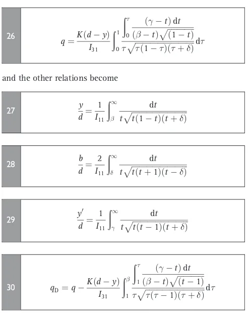
Quantity of drainage is therefore given by
and the other relations become
y
As the hodograph plane mapping remains unchanged, the expressions for drainage velocity do not alter, apart from¼0. The effect of the ditch width on the quantity of drainage is shown in Fig. 4, which reveals that the effect of ditch width on the drainage quantity is not substantial.
When the effect of width of the ditch is not taken into consideration, the point E0approaches to E (! 1) and therefore the seepage quantity becomes
q¼KðdyÞ
For this case Fig. 5 shows the variation in the drainage quantity and drainage from the non-seepage face with the depth of water in ditches, for different cases of ditch spacing. It is interesting to note that the drainage from the non-seepage face is at a maximum when the water depth in the ditch is 40% of the ditch depth, irrespective of the spacing between the ditches.
Further, if the water depth in the ditch is zero as well (¼¼ 1), then
which is the same as given by Youngs,29that is the drainage rate is the product of the hydraulic conductivity and the depth of the ditch in the case of an infinitely deep soil for the empty ditch condition.
3.2. Width of ditch very small
When the effect of width of the ditch is not taken into consideration, the point E0approaches to E (! 1) and with
¼ 1, the hodograph remains unchanged while the physical plane and theW plane relations become
Z¼id
Fig. 4. Effect of ditch width on the quantity of drainage for a single ditch
where
AlternateW plane mapping similar to equation (9) is given by
W¼iKðdyÞ
The expressions for drainage velocity remain unchanged, but other relations for accessory parameters and drainage discharge (q) deduced from equations (34), (35) and (38) are
y
Further if the spacings between the ditches are very large (¼0), then the present solution gets converted into a particular case of a single ditch and the quantity of drainage is expressed by equation (31).
3.3. Array of empty ditches
Drainage efficiency increases as the water depth in ditches decreases. If the water depth in ditches is maintained at zero for maximum efficiency, then the points D and D0approach E (! 1and! 1), thus the slit DD0E in the hodograph plane will disappear to give
dW
The physical plane mapping does not alter but theW plane becomes
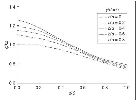
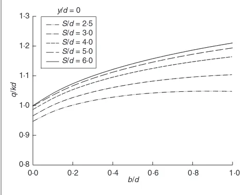
The accessory parametersandare computed using equations (16) and (17). Fig. 6 represents equation (46) and shows the effect of spacing on drain discharge in an empty ditch. The variation inqwith ditch width is shown in Fig. 7 for empty ditches.
Furthermore, if the ditch width is very small (¼ 1), then the hodograph mapping and physical mapping remains the same as equation (43) and equation (34) respectively but theW–plane mapping becomes
where
I35¼
ð1
0
ffiffiffiffiffiffiffiffiffiffiffi
þ1
p
ffiffiffiffiffiffiffiffiffiffiffiffi
þ1
p
ðÞ ffiffiffiffiffiffiffiffiffiffiffiffiffiffiffiffiffi
ð1þÞ
p d
49
The quantity of drainage is given by
q¼Kd
I35
ð1
0
ffiffiffiffiffiffiffiffiffiffiffi 1 p
ffiffiffiffiffiffiffiffiffiffiffiffi 1þ p
ðþÞ ffiffiffiffiffiffiffiffiffiffiffiffiffiffiffiffiffi
ð1Þ
p d
50
and the relation for finding the single accessory parameteris given by equation (40) or equation (40a). Moreover, if the spacing is very large then it becomes a single ditch and the quantity of drainage is given by equation (33).
4. EXAMPLE
Consider drainage of a homogeneous and isotropic porous medium of a ponded area 2.5 m deep and parallel ditches 0.6 m wide, spaced at 5.0 m. The water depth in the ditches is maintained at 0.6 m.
For the given datab/d¼0.24,S/d¼1.0 andy/d¼0.24, assuming negligible ponded water and using equations (15) to (17) and (19), the accessory parameters are¼13.8159;
¼7.4796;¼59.8989; and¼24.2498. With these parameters:q=Kd¼0.6465; qD=Kd¼0.3424;vB=K¼0.6651; andy0=d¼0.2083.
If the ditch is empty then¼10.9233 and¼50.0746, so q=Kd¼0.7151 andvB=K¼0.7104. Also if the spacing is very large, thenq=Kd¼0.9579 andqD=Kd¼0.2702.
5. DISCUSSION AND LIMITATIONS
Subsurface drainage may be achieved by adopting tile drains or ditch drains. One of the main drawbacks in the installation of a tile/pipe-type subsurface drainage system is high initial investment. The important advantages of open ditches are that they are easy to construct, have low initial cost and have the ability to carry large quantities of water; the disadvantages are interference with farming operations, removal of land,
requirement for regular maintenance and poor side slope stability.23In spite of these limitations an array of ditches may present an economical method of subsurface drainage. An array of ditches method of subsurface drainage is advantageous for various playgrounds, golf courses, parks and also for orchard plantations where there are few farming operations.
The presented analytical solution has been derived for an idealised porous medium and boundary conditions. There may be great variations in soil and boundary conditions in an actual field drainage case. The actual field problem has to be simplified to make it possible to obtain an analytical solution. As the solution only approximates field conditions, it is necessary to examine the assumptions made in its derivation before applying it to a particular field problem. In most cases the assumptions will not exactly correspond to the situation encountered in the field. In some cases the analytical solution may work quite well, in other cases it may be useful only as a first approximation to the proper design. In any case the analytical solutions provide a great deal of understanding of the problem in a rational way through their functional relationship between influencing parameters.
Also, the present solution is developed with an assumption that the ponded water will initially be drained out by surface field drains. At a later stage for small ponded water depth, the subsurface drainage by ditches will take place. Furthermore, if the porous medium is non-homogeneous then it should be transformed into an equivalent homogeneous medium30and thereafter the presented solution becomes applicable on the transformed problem.
6. CONCLUSIONS
Application of velocity hodograph and Schwarz–Christoffel transformation make it possible to obtain an exact analytical solution for the problem of subsurface drainage by an array of parallel ditches. The solution is applicable for an idealised porous medium and boundary conditions such as steady state subsurface drainage of a ponded surface in an homogeneous porous medium of infinite extent. The actual field problem may not satisfy these assumptions, hence the solution may work quite well in some cases and in other cases may be useful only as a first approximation. From the general solution, various particular solutions can easily be deduced for an array of ditches with very small ditch width and the empty ditch condition. The solution estimates drainage rate and drainage velocity in an array of ditches in ponded land. It may therefore be useful to practising engineers in controlling waterlogging and secondary salinisation in irrigated lands, cricket grounds, golf courses, race courses, parks and others amenities.
APPENDIX
Velocity hodograph30,31
Let the complex potentialW ¼þi be an analytical function of the complex variableZ, asW ¼fðZÞ. Differentiation ofW with respect toZ, yields
dW dZ ¼
@ @Xþi
@
@X¼
@
@Y i
@
@Y ¼uiv
51
The transformation of the region of flow fromZplane into the dW=dZplane is called the velocity hodograph. The utility of the
0·8 0·9 1·0 1·1 1·2 1·3
S/d = 2·5
S/d = 3·0
S/d = 4·0
S/d = 5·0
S/d = 6·0
y/d = 0
q
/
kd
b/d
0·0 0·2 0·4 0·6 0·8 1·0
hodograph stems from the fact that, although the shape of the free surface and the limit of the surface of seepage are not known initially in theZplane, their hodographs are completely defined in the dW=dZplane.
Generally, the various boundaries of a flow region in theZ plane are transformed first into theuþivplane, then the mirror reflections about theuaxis result into the velocity hodograph, that is theuivplane. The various boundary relations of the hodograph are
(a) at an impervious boundary the velocity vector is in the direction of the boundary; in theu–vplane a straight line passing through the origin and parallel to the impervious boundary represents the impervious boundary
(b) since a boundary of reservoir is an equipotential line, the velocity vector is perpendicular to the boundary, hence in the u–vplane a straight line passing through the origin and normal to the reservoir boundary represents the reservoir boundary
(c) a line of seepage (phreatic line) is a stream-line and along it
þKY¼constant, in theu–vplane a circle
(u2þv2þKv¼0) passing through the origin, with radius K=2 and centre at (0,K/2) represents the phreatic line (d) a surface of seepage in theZplane, which is neither a
stream-line nor an equipotential line, is represented by a straight line normal to the seepage surface and passing through the point (0,K) in theu–vplane.
Schwarz–Christoffel transformation30,31
The Schwarz–Christoffel transformation is a method of mapping a polygon consisting of straight-line boundaries, from one plane on to the upper/lower half of another plane. The transformation can be considered as the mapping of a polygon from theZplane on to a similar polygon in the
plane in such a manner that the polygon in theZplane is opened at some convenient point and then extended on one side to¼ 1and the other to¼ þ1along the real axis of theplane. Thus the transformation maps conformally the region interior to the polygon into the entire upper/lower half of the auxiliaryplane. For the polygon ABCDEE0F located in theZplane (Fig. 1(a)), the transformation that maps it conformally on to the upper half of the auxiliaryplane (Fig. 1(d)) is
dZ
d¼C1ðÞ
A11ðÞA21ðÞA31 . . .
52
Z¼C1
ð
0
dt
ðtÞ1A1ðtÞ1A2ðtÞ1A3 . . .þ
C2 53
whereA1;A2;A3;. . .are the interior angles (fraction of) of the polygon in theZplane, and; ; ;. . .
ð1< < < <. . .<1) are the points on the real axis of theplane corresponding to the respective vertices. Any three of the values; ; ;. . . can be chosen arbitrarily to correspond to three of the vertices of the given polygon. The (N3) remaining values must then be determined so as to satisfy conditions of similarity. The interior angle at the point of opening may be regarded as, hence it takes no part in the transformation. Also the vertex of the polygon placed at infinity
in theplane does not appear in the transformation. Thus by mapping a vertex of the flow region into one at infinity in the auxiliary plane omits the vertex factor from the transformation and reduces one unknown. Using values ofA1;A2;A3;. . .from Fig. 1(a) and; ; ;. . .from Fig. 1(a), equation (53) reduces to equation (1).
REFERENCES
1. SINGHR. M., SINGHK. K. and SINGHS. R. Water table
fluctuation between drains in the presence of exponential recharge and depth-dependent evapotranspiration.ASCE Journal of Irrigation and Drainage Engineering, 2007,133, No. 2, 183–187.
2. BUREAU OFINDIANSTANDARDS.Glossary of terms relating to
farm drainage.BIS, New Delhi, 1986, IS: 11493.
3. RHOADESJ. D. Soil salinity—causes and control.In
Techniques for Desert Reclamation.(GOUDIEA. S. (ed.)). Wiley, New York, 1990.
4. MANJUNATHM. V., OOSTERBAAN R. J., GUPTA S. K.,
RAJKUMAR H. and JANSENH. Performance of subsurface
drains for reclaiming waterlogged saline lands under rolling topography in Tungabhadra irrigation project in India. Agricultural Water Management, 2004, 69, No. 1, 69–82.
5. BHATTACHARYAA. K. Drainage of agricultural lands.In50
Years of Natural Resources Management Research. Division of Natural Resources Management(SINGHG. B. and SHARMA
B. R. (eds)). ICAR, Krishi Bhavan, New Delhi, India, 1999, pp. 347–362.
6. SARANGIA., SINGHM., BHATTACHARYAA. K. and SINGHA. K.
Subsurface drainage performance study using SALTMOD and ANN models.Agricultural Water Management, 2006,
84, No. 3, 240–248.
7. KACIMOVA. R. Seepage to a drainage ditch and optimization
of its shape.ASCE Journal of Irrigation and Drainage Engineering, 2006,132, No. 6, 619–400.
8. AMERM. H. andDERIDDERN. A. (eds).Land Drainage in Egypt. DRI, Egypt, 1989.
9. FRAMJIK. K., GARGB. C. and LUTHRAS. D. L.Irrigation and
Drainage in the World, a Global Review.International Commission on Irrigation and Drainage, New Delhi, 1982.
10. INTERNATIONALCOMMISSION ONIRRIGATION ANDDRAINAGE(ICID). Research on the Control of Waterlogging and Salinization in Irrigated Agricultural Lands, Volume 4. Central Soil Salinity Research Institute, India,2003.
11. RITZEMAH. P., NIJLANDH. J. and CROONF. W. Subsurface drainage practices: From manual installation to large-scale implementation.Agricultural Water Management, 2006,86,
No. 1–2, 60–71.
12. ARVINV. I. and NUMEROVS. N.Theory of Flow in Undeformable Porous Media.Israel Programme for Scientific Translations, Jerusalem, 1965.
13. BARUAG. and TIWARIK. N. Analytical solution of seepage
into ditches from ponded field.ASCE Journal of Irrigation and Drainage Engineering, 1995,121, No. 6, 396–404. 14. DAGANG. Spacing of drains by an approximate method.
ASCE Journal of Irrigation and Drainage Engineering, 1964,
90, No. IR1, 41–46.
16. ILYINSKYN. B. and KACIMOVA. R. Problems of seepage to empty ditch and drain.Water Resource Research,1992,28,
No. 3, 871–877.
17. KACIMOVA. R. Steady two dimensional flow of groundwater to a trench.Journal of Hydrology,1991,127, No. 1–4,
71–83.
18. KIRKHAMD. Flow of ponded water into drain tubes in soil
overlying an impervious layer.Transactions of the American Geophysical Union, 1949,30, No. 3, 369–385. 19. KIRKHAMD. Seepage into ditches in the case of a plane
water table and an impervious substratum.Transactions of the American Geophysical Union, 1950,31, No. 3, 425–430.
20. KIRKHAMD. Seepage into ditches from a plane water table overlying a gravel substratum.Journal of Geophysical Research, 1960,65, No. 4, 1267–1272.
21. KIRKHAMD. Seepage of leaching water into drainage ditches of unequal water level heights.Journal of Hydrology,1965,
3, No. 3–4, 207–224.
22. KIRKHAMD. Steady state theories for drainage.ASCE Journal of Irrigation and DrainageEngineering, 1966,92, No. IR1, 19–39.
23. LUTHINN. L.Drainage Engineering.Wiley, New York, 1966.
24. WARRICKA. W. and KIRKHAMD. Two dimensional seepage of ponded water to full ditch drains.Water Resource Research, 1969,5, No. 3, 685–693.
25. YOUNGSE. G. Horizontal seepage through unconfined aquifers with hydraulic conductivity varying with depth. Journal of Hydrology, 1965,3, No. 3–4, 283–296. 26. YOUNGSE. G. The effect of the depth of an impermeable
barrier on water table heights in drained homogeneous soils.Journal of Hydrology, 1975,24, No. 3–4, 283–290. 27. YOUNGSE. G. An examination of computed steady state
water table heights in unconfined aquifers: Dupuit– Forchheimer estimates and exact analytical results.Journal of Hydrology, 1990,119, No. 1–4, 201–214.
28. YOUNGSE. G. and LEEDS-HARRISONR. B. Improving efficiency of desalinization with subsurface drainage.ASCE Journal of Irrigation and Drainage Engineering, 2000,126, No. 6,
375–380.
29. YOUNGSE. G. Seepage to ditches from a ponded surface. Journal of Hydrology,1994,161, No. 1–4, 145–154.
30. HARRM. E.Groundwater and Seepage.McGraw Hill, New York, 1962.
31. POLUBARINOVA-KOCHINAP. Y.Theory of Ground Water Movement.Princeton University Press, Princeton, New Jersey, 1962.
What do you think?
To comment on this paper, please email up to 500 words to the editor at [email protected]