THE SYSTEM OVERVIEW AND GEOMETRIC IMAGE QUALITY OF THE TH-1
SATELLITE
Jianrong Wang a,b,*, Xin Hu a aXi’an Institute of Surveying and Mapping, Xi’an, China–
b Faculty of Geo-Information Science and Earth Observation (ITC) of University of Twente, Enschede, The Netherlands – [email protected]
Commission I, WG I/5
KEY WORDS: Location accuracy, Satellite photogrammetry, On-orbit calibration, Bundle adjustment, Low-frequency errors, Line-Matrix CCD camera
ABSTRACT:
The Tian-Hui 1 (TH-1) is the first stereo mapping transmission satellite in China, and the primary mission goal of the satellite is for topographic mapping at 1:50,000 scale without Ground Control Points (GCPs). 1st, 2nd and 3rd satellite of TH-1 was launched on August 24, 2010, May 6, 2012 and October 26, 2015. In TH-1 satellite, many payloads are put on a small satellite platform, which has a low cost. The optical camera of TH-1 includes Line-Matrix CCD (LMCCD) camera, high resolution camera and multispectral camera with 60 km ground swath width. To get high geometric accuracy without GCPs, the on-orbit calibration camera parameters and the Equivalent Frame Photo (EFP) Multi-functional bundle adjustment are proposed and realized in ground image processing of TH-1. In order to evaluate the location accuracy of TH-1, some testing fields are established. All GCPs of testing fields are measured by GPS. The GCPs are not participated the EFP Multi-functional bundle adjustment, and are only as Check Points (CPs) to evaluate the location accuracy. The evaluation of 1st satellite is shown: the horizontal accuracy is 10.3 m (RMSE) and the vertical accuracy is 5.7 m (RMSE) without GCPs, which can satisfy for topographic mapping at 1:50,000 scale. The overviews of TH-1 satellite are described in this paper: First, the system overview is introduced, including mission and optical camera of TH-1. Then, the on-orbit calibration camera parameters using LMCCD image and the EFP Multi-functional bundle adjustment are presented. Finally, the location performance is analysed without GCPs and with different number of GCPs. In addition, the products of TH-1 are introduced.
* Corresponding author
1. INTRODUCTION
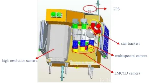
The Tian-Hui 1 (TH-1) satellite is the first stereo mapping transmission satellite in China, which is for topographic mapping at 1:50,000 scale without Ground Control Points (GCPs). 1st satellite of TH-1 was launched on August 24, 2010, 2nd satellite on May 6, 2012, and 3rd satellite on October 26, 2015. Now, three satellites of TH-1 are well operating on their orbit. TH-1 satellite is placed in a 500 km sun synchronous orbit with the orbital inclination of 97 degrees. The optical camera of TH-1 consists of Line-Matrix CCD (LMCCD) camera with ground pixel size of 5 m; high resolution camera with ground pixel size of 2 m and multispectral camera with ground pixel size of 10 m, and the ground swath width of all optical system is 60 km. While scanning using push-broom pattern, the satellite position is measured by Global Positioning System (GPS), and the satellite attitudes are measured using three star trackers. After ground data processing, the initial exterior orientation elements can be acquired with stereo images.
The integrated design with multi-function payloads is realized based on a small satellite platform (see Figure 1), and the weight of satellite is about 1000 kg (Hu Xin, 2014). The theories of on-orbit calibration camera parameters and Equivalent Frame Photo (EFP) Multi-functional bundle adjustment are proposed and realized in ground image processing: First, based on aerial triangulation bundle adjustment using LMCCD image (Wang Renxiang, 2006),
calibration models are proposed and the camera parameters are calculated using experimental field data. Second, the EFP Multi-functional bundle adjustment is put forward and realized to refine the exterior orientation elements without GCPs. After on-orbit calibration and EFP Multi-functional bundle adjustment, the high geometric accuracy is achieved without GCPs, which the horizontal accuracy is 10.3 m (RMSE) and the vertical accuracy is 5.7 m (RMSE) (Wang Renxiang et al., 2013). In this paper, system overview of TH-1 is introduced, the key technical in ground image processing are presented, the location performance is analysed without GCPs and with different number of GCPs, and the products of TH-1 are introduced.
Figure 1. The main payloads of TH-1 satellite
2. THE CAMERA OF TH-1
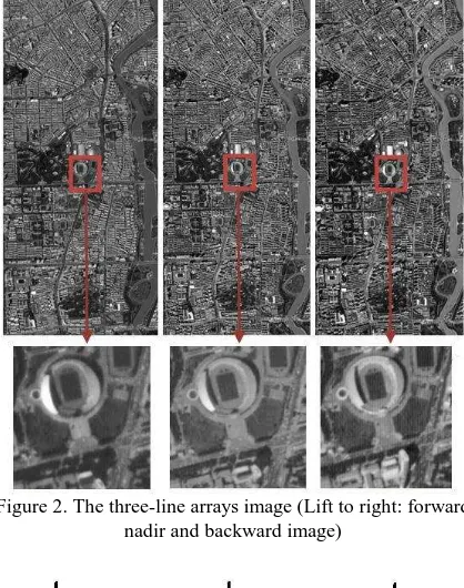
The camera of TH-1 includes LMCCD camera, high resolution camera and multispectral camera. LMCCD camera is a special stereoscopic camera, which is put forward to resist the systematic distortion in bundle adjustment. The LMCCD camera is composed of three-line arrays CCD camera and four small matrix array cameras (Wang Renxiang et al., 2004). The three-line arrays CCD camera includes forward, nadir and backward camera. Each camera has a single CCD array of 12,000 detectors at 5 meters resolution (see Figure 2). The looking lens of forward and backward camera is inclined with respect to the nadir looking lens by ±25. The B/H ratio is 1.0, which can get high vertical accuracy in three-dimensional intersection. The four small matrix array cameras are assembled on the focal plane of nadir camera, and are distributed symmetrically (see Figure 3). During photographing of three-line arrays CCD camera, the matrix array cameras take photographs at regular interval (about 3.2 seconds in TH-1), and the images are shown in Figure 4.
Figure 2. The three-line arrays image (Lift to right: forward, nadir and backward image)
Figure 3. Relationship between three-line arrays and four matrix arrays
Figure 4. The nadir image and matrix array images
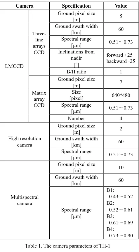
The high resolution camera has eight TDI (Time Delayed and Integration) CCD devices, which are spliced one line with staggered. The three-reflection of off-axis optical system is used in the high resolution camera and the resolution is 2 m with 60 km of ground swath width (see Figure 5). In addition, there is a multispectral camera for getting multispectral image (see Figure 6). The details of camera are shown in Table 1.
Figure 5. Tianjin image taking from high resolution camera
Figure 6. Changchun image taking from multispectral camera
Camera Specification Value
Table 1. The camera parameters of TH-1
3. THE KEY TECHNICAL IN GROUND IMAGE PROCESSING
3.1 On-orbit Calibration Camera Parameters
The values of geometric parameters, calibrated in the laboratory, differ from those in an on-orbit operation due to launch shock, temperature, and gravity release (Mulawa, 2004; Wang Renxiang et al., 2006), and the changes of geometric parameters will affect the location accuracy and efficiency of the satellite images. Thus, the on-orbit calibration geometric parameters are performed in many satellites using data of experimental field (Wolfgang Kornus et al., 2000; Grodecki et al., 2002; Gruen et al., 2007; Breton et al, 2002; Srinivasan et al., 2008; Jiang Yonghua et al., 2013). The self-calibration using additional parameters and the aerial triangulation bundle adjustment are two methods to calibrate the geometric parameters on-orbit. When using additional parameters, the number of additional parameters is important and may lead to different results (Fraser, 1982). While using aerial triangulation bundle adjustment, the geometric parameters can be calculated as unknown parameters without evaluating their number in advance, and the results can describe the changes in each geometric parameter. But, there is a premise to calibrate that the model of route has no obvious
systematic distortion during aerial triangulation bundle adjustment.
The aerial triangulation bundle adjustment is applied in on-orbit calibration in TH-1. The geometric calibration models of TH-1 are established using LMCCD image based on the theory of EFP bundle adjustment. The matrix array image points of LMCCD image are true frame image coordinates, which have a rigorous geometric relationship. During calculation the camera parameters using bundle adjustment, the matrix array image points are participated as a tie point instead of the line array image points (see Figure 7), which can solves the systematic distortion of routes model (Wang Renxiang et al., 2004). There are 12 geometric parameters to be calculated in TH-1, including interior orientation elements of each CCD line array camera and the angle corrections from star tracker frame to nadir camera. After on-orbit calibration camera parameters, the changes of the principal distance are about 1-2 m, and the changes of intersection angle between forward and backward camera are about 10. As we known, strongly correlated exists between principal distance and intersection angle, and they can get a good results after combination (Wang Renxiang, 2006). The changes of principal point across track are about 2-5 pixel. While, the changes of angle corrections from star tracker frame to nadir camera are larger, and the maximum is 69, which could lead to a large error of location accuracy. The on-orbit calibration of TH-1 is performed about four times every year, and the geometric parameters should be updated regularly.
Figure 7. Distribution of image point for calibration camera parameters
To get high quality image, the radiometric parameters are calibrated. First, according to the data of target field and atmospheric optical properties, the absolute radiometric calibration coefficients and the spectrum dynamic range are calculated, which can calibrate the absolute radiometric parameters. Second, using the uniform feature region of satellite images, the relative radiometric coefficient of each detector is calculated to calibrate the relative radiometric parameters. In addition, the calibration of resolution and dynamic Modulation Transfer Function (MTF) are performed to assess the radiometric image quality.
3.2 The EFP Multi-functional bundle adjustment
The bundle adjustment of three-line arrays image is to solve the orientation of image, which can get high accuracy exterior orientation parameters. The Orientation Image (OI) bundle adjustment (Hofmann, 1986) and EFP bundle adjustment are two methods, in which the exterior orientation parameters are calculated only for so-called orientation points or EFP time. In between two orientation points, the exterior orientation parameters of each three-line image are expressed as polynomial functions of the parameters at the neighboring orientation points.
However, the OI and EFP bundle adjustment cannot achieve topographic mapping without GCPs (Ebner et al., 1991; Wang Renxiang, 2006). Then, the EFP Multi-functional bundle adjustment was developed (Wang Jianrong et al., 2012). First, the EFP Multi-functional bundle adjustment can process not only the long image (about 1000 km), but also the short image (at least 60 km) using whole three intersection areas (Wang Renxiang et al., 2014). Second, during photographing, there are low-frequency errors of the attitude determination system (Wang Renxiang et al., 2011), which may be caused by in-flight time and latitude using star tracker (Bouillon et al., 2003). This phenomenon will make the exterior orientation parameters involving the errors of low-frequency and lead to the large errors of position. In SPOT5 satellite, the latitudinal model (Bouillon et al., 2003) was proposed to correct attitude using approximately 20 calibration sites data. However, the EFP Multi-functional bundle adjustment can compensate low-frequency errors using stereo image themselves without the calibration sites data. Finally, in order to maintain effective ground coverage of stereo image, the drift angle correction is implemented in satellite, which would cause three-line arrays image exiting the large vertical parallax. The vertical parallax can be reduced using stereo image during EFP Multi-functional bundle adjustment (Wang Jianrong et al., 2014). After the EFP Multi-functional bundle adjustment, the vertical parallax can reach 0.3 pixel and the exterior orientation parameters have been further refined.
4. THE LOCATION PERFORMANCE AND PRODUCTS OF TH-1
4.1 Ground testing fields
In order to assess the location performance of TH-1, fields for testing the accuracy are established and distributed in different places in China, and include different terrains (see Table 2). All GCPs of testing fields are measured by GPS, and their accuracies are considered as 0.5 m in horizontal and vertical. The GCPs are not participated the EFP Multi-functional bundle adjustment, and are only as Check Points (CPs) to evaluate the location accuracy.
Testing Field Terrain Height [m]
Table 2. Ground testing fields of TH-1
4.2 Location performance
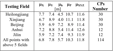
Using three-line arrays image of testing fields, initial exterior orientation parameters and on-orbit calibration camera parameters, the EFP Multi-functional bundle adjustment is performed and high accuracy exterior orientation parameters are calculated. Based on the exterior orientation parameters and on-orbit calibration camera parameters, Rational Polynomial Coefficients (RPCs) of forward, nadir and backward image are generated without GCPs. Finally, based on three-line arrays image and their RPCs, the location performance is assessed by many CPs. The location accuracies of 1st satellite without GCPs are shown in Table 3.
Table 3. Statistics of location accuracy without GCPs
In Table 3, X is RMSE of X coordinate, Y is RMSE of Y coordinate, h is vertical accuracy (RMSE), P is horizontal accuracy (RMSE), and XYZ is RMSE of three-axis ground coordinate.
From Table 3 can be seen, the location accuracy of each testing field is about 12 m, and the maximum is 12.6 m. The changes of location accuracy of 5 testing field are little, which means consistency of location accuracy in TH-1. Added up all CPs of 5 testing fields, the location accuracy reaches 11.8 m, in which vertical accuracy is 5.7 m and horizontal accuracy is 10.3 m. After the EFP Multi-functional bundle adjustment, the accuracy can satisfy for topographic mapping at 1:50,000 scale without GCPs.
In addition, the location accuracy of 1st satellite using GCPs is also performed. When using GCPs in photogrammetry processing, the GCPs are only to refine the RPCs. The location performance using GCPs of TH-1 is assessed with different Table 4. Statistics of location accuracies with GCPs
In Table 4, compared to the location accuracies without GCPs, the vertical accuracy and horizontal accuracy have been improved. However, the improvement of accuracy is not significant, which may affect by measurement accuracy of image points and the range size of image. For example, the length of Heilongjiang field is 315 km with 8 GCPs, and the location accuracy will be improved if length is 60 km with 4 GCPs. This study will be carried out in the future.
When the GCPs are participated the processing, the number and distribution of GCPs are determining the location accuracy. To analysis the effect of number and distribution of GCPs, Xinjiang field is selected as a sample. Using the 4 GCPs, the points are distributed on the start and the end of the image. With the GCPs added, the points are distributed evenly and symmetrically. The location accuracies are shown in Table 5.
X Y h P XYZ
Table 5. Statistics of location accuracies with different number of GCPs in Xinjiang field
From the Table 5 can be seen, though the length of field image is 270 km, the location accuracy with GCPs is about 9 m and is approaching using 4 GCPs or more. The results are shown that the interior precision of three-line arrays image is well, and the three-line arrays CCD camera has high geometric property.
4.3 Products of TH-1
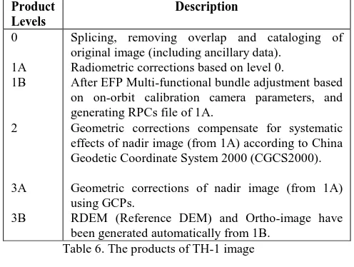
There are a variety of processing levels and data formats of TH-1 image for different users (Hu Xin, 20TH-14), and the description of each product is listed in Table 6. The format of image (exception level 0) is GeoTiff, which nearly all photogrammetric and GIS software support. Some products provide orientation file with RPCs, which represent the geometric relationship of ground-to-image. The format of RPC is standard, and the user can perform photogrammetric processing without considering the geometric parameters of camera using photogrammetric software.
Splicing, removing overlap and cataloging of original image (including ancillary data).
Radiometric corrections based on level 0.
After EFP Multi-functional bundle adjustment based on on-orbit calibration camera parameters, and generating RPCs file of 1A.
Geometric corrections compensate for systematic effects of nadir image (from 1A) according to China Geodetic Coordinate System 2000 (CGCS2000).
Geometric corrections of nadir image (from 1A) using GCPs.
RDEM (Reference DEM) and Ortho-image have been generated automatically from 1B.
Table 6. The products of TH-1 image
5. CONCLUSION
The primary mission goal of TH-1 is for topographic mapping at 1:50,000 scale without GCPs. In order to achieve its goal, the on-orbit calibration camera parameters based on LMCCD image and EFP Multi-functional bundle adjustment are put forward and realized in ground image processing, and the initial interior and exterior orientation parameters have been further refined. Using the orientation parameters, RPCs of three-line arrays image are generated. Based on stereo image with RPCs, the location accuracy of TH-1 is assessed systematically using many CPs from 5 testing fields. In this paper, the location performance of 1st satellite is presented without GCPs and with different number of GCPs. The results indicate that the horizontal accuracy and the vertical accuracy can fulfil for topographic mapping at 1:50,000 scale without GCPs. The location performance of 2nd satellite is equivalent with 1st
satellite, and location performance of 3rd satellite is ongoing evaluating systematically. In addition, variety of products will satisfy for different users in the field of photogrammetry and remote sensing.
ACKNOWLEDGEMENTS
This study is funded by the China Scholarship Council (CSC). The first author thanks the Faculty of Geo-information Science and Earth Observation (ITC) of the University of Twente for providing a good research environment.
REFERENCES
Bouillon, A., Breton, E., De Lussy, F., Gachet, R., 2003. SPOT5 geometric image quality. Proceedings of 2003 IEEE International Geoscience and Remote Sensing Symposium, Vol. I (2003), pp. 303–305. Toulouse, France.
Breton, E., Bouillon, A., Gachet, R., Delussy, F., 2002. Pre-flight and in-Pre-flight geometric calibration of SPOT5 HRG and HRS images, ISPRS Comm.I, Denver, pp. 10-15.
Ebner, H., Kornus, W., Ohlhof, T. A., 1991. Simulation study on point determination using MOMS-02/D2 imagery. Photogrammetric Engineering & Remote Sensing, pp. 1315-1320.
Fraser, C. S., 1982. Film unflatness effects in analytical non-metric photogrammetry. International Archives of Photogrammetry and Remote Sensing, pp. 156-166.
Grodecki, J., Dial, G., 2002. Ikonos geometric accuracy validation. Pecora 15/Land Satellite Information IV/ISPRS Commission I/FIEOS Conference Proceedings.
Gruen, A., Kocaman, S., Wolff, K. 2007. Calibration and validation of early ALOS/PRISM images. The Journal of the Japan Society of Photogrammetry and Remote Sensing, 46(1), pp. 24-38.
Hofmann, O., 1986. The stereo-push-broom scanner system DPS and its accuracy. International Geoscience and Remote Sensing Symposium, pp. 21-28.
Hu Xin, 2014. TH-1 satellite engineering and application. Publishing House of Surveying and Mapping, Beijing.
Jiang Yonghua, Zhang Guo, Tang Xinming, Zhu Xiaoyong, Qin Qianqing, Li Deren, Fu Xinke, 2013. High accuracy geometric calibration of ZY-3 three-line image. Acta Geodaetica et Cartographica Sinica, 42(4), pp. 523-529.
Mulawa, D., 2004. On-orbit geometric calibration of the OrbView-3 high resolution imaging satellite. International Archives of the Photogrammetry, Remote Sensing and Spatial Information Sciences, 35(B1), pp. 1–6.
Srinivasan, T.P., Islam, B., Singh, S. K., Krishna, B. G., Srivastava, P. K., 2008. In-flight geometric calibration-an experience with Cartosat-1 and Cartosat-2. The International Archives of the Photogrammetry, Remote Sensing and Spatial Information Sciences Vol. XXXVII, Part B1, Beijing.
Wang Renxiang, Hu Xin, Wang Jianrong, 2013. Photogrammetry of mapping satellite-1 without ground control points. Acta Geodaetica et Cartographica Sinica, 42(1), pp.1-5.
Wang Renxiang, 2006. Satellite photogrammetric principle for three-line array CCD imagery. Publishing House of Surveying and Mapping, Beijing.
Wang Renxiang, Hu Xin, Yang Junfeng, Wang Xinyi, 2004. Proposal LMCCD camera for satellite photogrammetry. Acta Geodaetica et Cartographica Sinica, 33(2), pp. 116-120.
Wang Renxiang, Wang Jianrong, Zhao Fei, Liu Wei, 2006. Dynamic calibrating of three-line-array CCD camera in satellite photogrammetry using ground control point. Journal of Earth Sciences and Environment, 28(2), pp. 1-5.
Wolfgang Kornus, Manfred Lehner, Manfred Schroeder, 2000. Geometric in-flight calibration of the stereoscopic line-CCD scanner MOMS-2P, ISPRS Journal of Photogrammetry and Remote Sensing, 55(1), pp. 59-71.
Wang Jianrong, Wang Renxiang, 2012. EFP multi-functional bundle adjustment of mapping satellite-1 without ground control points. Journal of Remote Sensing, Vol.16, pp. 112-115.
Wang Renxiang, Wang Jianrong, Hu Xin, 2011. Study on the photogrammetry of in-flight satellite without ground control point. Geomatics and Information Science of Wuhan University, 36(11), pp. 1261-1264.
Wang Renxiang, Wang Jianrong, HU Xin, 2014. The EFP bundle adjustment of all three line intersection. Geomatics and Information Science of Wuhan University, 39(7), pp. 757-761.
Wang Jianrong, Wang Renxiang, Hu Xin, 2014. Drift angle residual correction technology in satellite photogrammetry. Acta Geodaetica et Cartographica Sinica, 43(9), pp. 954-959.