This content has been downloaded from IOPscience. Please scroll down to see the full text.
Download details:
IP Address: 103.9.183.251
This content was downloaded on 27/02/2017 at 07:53
Please note that terms and conditions apply.
Design of heart rate monitor based on piezoelectric sensor using an Arduino
View the table of contents for this issue, or go to the journal homepage for more 2017 J. Phys.: Conf. Ser. 795 012016
(http://iopscience.iop.org/1742-6596/795/1/012016)
Home Search Collections Journals About Contact us My IOPscience
You may also be interested in:
Assessment of piezoelectric sensor adhesive bonding T Wandowski, J Moll, P Malinowski et al.
Erratum: Measuring the RC time constant with Arduino (2016 Phys. Educ. 10 065007) N S A Pereira
Piezoelectric Sensors Using Rubber Sensing Film Kohji Hohkawa, Atusi Kaneko, Keishin Koh et al.
Shock wave velocity measuring system based on vernier VISAR-type interferometers K L Gubskii, D S Koshkin, A S Antonov et al.
Using the Arduino with MakerPlot software for the display of resonance curves characterisic of a series LCR circuit
Keith Atkin
Confirmation of the Distribution of Measured Values from an Ultrasound Fetal Heart Rate Monitor Yasuaki Noguchi, Takeo Hamada, Fujihiko Matsumoto et al.
Wireless Control of Miniaturized Mobile Vehicle for Indoor Surveillance Syed M Taha Saquib, Sarmad Hameed, Syed M Usman Ali et al.
A motion artifact generation and assessment system for the rapid testing of surface biopotential electrodes
Alper Cömert and Jari Hyttinen
Design of heart rate monitor based on piezoelectric sensor
using an Arduino
Veni Setyowati1*, Jodelin Muninggar1, Made R. S. Shanti.N.A1,2 1
Department of Physics
2
Department of Physics Education,
Faculty of Science and Mathematics, Universitas Kristen Satya Wacana
Jl. Diponegoro No.52-60, Salatiga, Sidorejo, Kota Salatiga, Jawa Tengah 50711, Indonesia
*) E-mail: [email protected]
Abstract. Reading of result heart rate using an acoustic stethoscope needs a particular skill, quiet environment, and hearing sensitivity. This project had the purpose design of a user-friendly automatic heart rate monitor and especially in a noisy area which to eliminate problems and incorrect reading of result. The liquid crystal display shows a heart rate as a result of measurements. The design of the heart rate monitor has two main parts; the signal recorder that a piezoelectric sensor, a filter, and an amplifier as recorder. The second parts was Arduino microcontroller with reinforced. Besides, three supporting buttons provided as the
manual switches, the „on‟, the „start‟, and „reset‟ buttons. The values acquired from the heart rate monitor indicate that those were on the Vernier BPS-BTA value range. The measurement error factor of the heart rate monitor then compared to the Vernier BPS-BTA test device was 3.15%. Besides, the value of statistical independent-test indicates that there is no significant difference (P = 0.971) between the heart rate monitor device and the Vernier BPS-BTA. In conclusion, this device was ready to be used because it has almost the same accuracy with the standart device.
Corresponding author: [email protected]
ICSAS IOP Publishing
1. Introduction
The heart is an organ which pumps blood throughout the body and return to the heart as the effect of my card contraction. The tricuspid valves and bicuspid valves can open and to close automatically [7, 15]. This condition is useful to ensure that the blood flows to aortic and periphery area with the pulse characteristics [8, 9]. The hearts distinctive rhythm is an indicator to diagnose of heart diseases[1, 16, 12] which have a distinctive rhythm at frequency 20-800 Hz which can be listened by ears [5]. On a medical check-up, one of the diagnosis devices which have high accuracy existence is acoustic stethoscopes. There are several factors that influence the diagnosis accuracy on the utility of acoustic stethoscope. There is the sound (pulse) on the chest wall or blood vessels which recorded, the heartbeat that can be perceived by human ears and environmental condition [2]. Those factors make the stethoscope utility on diagnostic by medical experts [5]. Based on those factors, the acoustic stethoscope is applied for calculating of heart rate. Therefore, heart rate monitor device to applied and operated in a noisy environment. This study to design a device for calculate heart rate automatically using a piezoelectric sensor which controlled by an Arduino. Hopefully, it used as a learning media for healthcare students or medical physics.
2. Methode
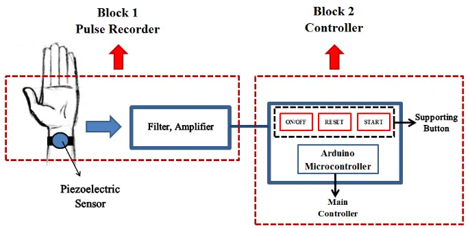
Figure 1. The design of heart rates monitor
Figure 1 show an automatic design of heart rate. The device divided into two main blocks. The first was pulse recorder block, which consists of a piezoelectric sensor, a filter and an amplifier (Op-Amp). The piezoelectric sensor was medically used to convert sound energy in the body into electrical pulse [10-13]. The piezoelectric sensor was put on the heart pulse on the wrist using a mild pressure, the sensor placed as close as possible to the heart rate to record it [3, 14]. The sign of detected heart rate to show by the flashing lights between the filter and amplifier circuits, as shown in Figure 2. The pulse recorded and filtered by the piezoelectric sensor. The function of a filter was to minimize the error during the pulse recording [17]. The filtered pulse was not added a new frequency from the recorded input because the filter converts the size of amplitude small relatively only. Therefore, an amplifier is needed to amplify the output signal produced by the piezoelectric sensor.
ICSAS IOP Publishing
IOP Conf. Series: Journal of Physics: Conf. Series 795(2017) 012016 doi:10.1088/1742-6596/795/1/012016
Figure 2. Filter, Amplifier, and Piezoelectric sensor Source: www. Indo-ware.com [4]
The second was an amplifier controller block using an Arduino microcontroller. The Microcontroller Arduino Hardware was designed for a simple open hardware in an Arduino board using Atmel processor support and onboard I/O [6, 8]. The Arduino microcontroller functions to convert the recording from piezoelectric sensor and to count the heart rate for 60 seconds which displayed on an LCD in BPM (Beat per Minute). Besides, three supporting buttons are available in this device as manual switches: the "on", the "start", and the "reset" buttons. Those three buttons have an
important role in calculating the heart rate. When the “on” button, pressed to connect the power
supply, the device will prepare every component to be ready. The “start” button pressed, the heart rate calculating runs automatically and stops after 60 seconds. Restarting the calculating will be done by
pressed the “reset” button.
3. Results and Discussion
Figure 3. The Device Circuit
ICSAS IOP Publishing
Figure 2 show the circuit of the heart rate monitor device design. The device packed in a casing. Then, the heart rate monitor based on piezoelectric sensor using an Arduino, showed on Figure 4.
Figure 4.c.The position sensor Figure 4.d. The counting stops automatically
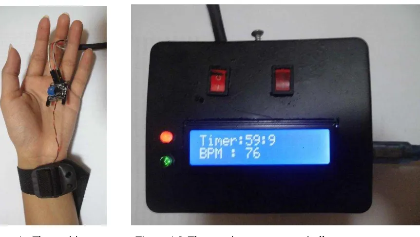
Figure 4a show the display of the design of heart rate monitor. At the time the device turned on by
pressing the “start” button, it says “waiting…” on the monitor before starting the calculating as shown in Figure 4b, then “BPM” will appear on the screen but the calculating has not started. At the moment
after “waiting …” appears. The piezoelectric sensor has put on the wirst band within a mild pressure as seen on figure 4.c. Then, the calculating start and stop automatically after 60 seconds, showed on Figure 4.d.
The heart rate monitor device is tested by compared to another device, the Vernier BTS-BTA, to get count of the heart rate in BPM (Beat per Minute). The comparisons of heart beat five samples
Figure 4a. The heart rate monitors display
Figure 4.b. Appear “waiting. . .” on the display when the device is going to start the data calculating Figure 4.a. The heart rate monitor display
ICSAS IOP Publishing
IOP Conf. Series: Journal of Physics: Conf. Series 795(2017) 012016 doi:10.1088/1742-6596/795/1/012016
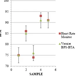
measuring the automatic heart rate monitor designed with the Vernier BPS-BTA are showed in Table 1. The data from five samples using the heart rate monitor within the standard deviation were: sample 1 (75 ± 5) BPM, sample 2 (86 ± 2) BPM, sample 3 (74 ± 1) BPM, sample 4 (93 ± 3) BPM, and sample 5 (93 ± 3) BPM. The result compared to Vernier BPS-BTA, and the results were: sample 1(75±4) BPM, sample 2 ( 85 ± 4 ) BPM, sample 3 (76 ± 5 ) BPM, sample 4 ( 91 ± 5 ) BPM, and sample 5 ( 91 ± 2 ) BPM. The values acquired from the heart rate monitor indicate that those count on the Vernier BPS-BTA value range.
Table 1. Comparison result of the heart rate monitor (HRM) device to Vernier BPS-BTA
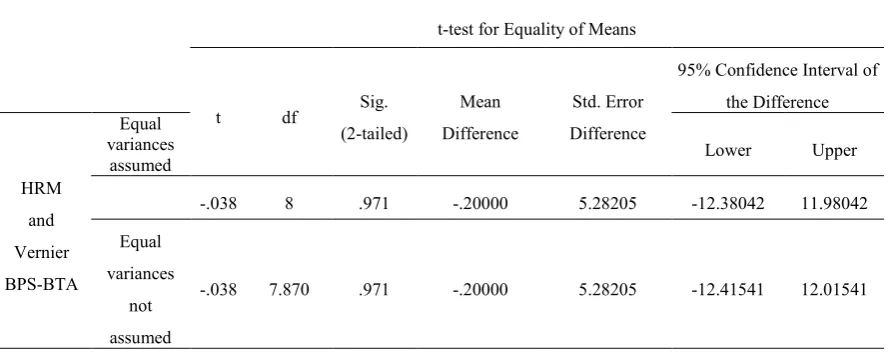
The proportion of calculating error factor of the heart rate monitor device was 3.15%, as shown in Table 1. While the distribution of the five samples testing results between the heart rate monitor and the comparator device the Vernier BPS-BTA, showed in Figure 5. The result calculation of the Vernier BPS-BTS has the standard deviation in the range of the data from the calculation result use the automatic heart rate monitor. Therefore, the heart rate monitor was possible as a learning media for healthcare students or medical physics in calculating the heart rate. Besides, independent t-test performed, and the result shows that there was no significance differences (P=0.971) between the heart rate monitor and the Vernier BPS-BTA (Table 2).
Table. 2. The comparison result of Heart Rate Monitor (HRM) and Vernier BPS BTA with Statistical Test used Independent T-Test
4. Conclusion
The heart rate monitor based on the piezoelectric sensor using an Arduino possible used everyone even in a noisy environment which does not need hearing sensitivity. To use this device, a piezoelectric sensor is put on the heart pulse on the wrist with a mild pressure so that the sensor is as close as possible to the sound of a heartbeat.
5. Acknowledgments
This research was supported by Department physics, Science and Mathematics faculty, Universitas Kristen Satya Wacana.
6. Reference
[1] Shu Yi, Li Cheng, Wang Zhe, Mi Wentian, Li Yuxing, Ren Tian-Ling 2015 MDPI AG 153224 [2] Mangion Kenneth. 2007 Malta Medical Journal19 41.
[3] Sujatha E, Y Radha 2013 International Journal of Scientific Research 2 206
[4] Indoware Piezoelectric Sensor https://www.indo-ware.com/produk-2856-piezoelektrik-piezo-elektrik-sensor-getar-indoware.html, accessed on 15 August 2016.
[5] Nolmanee Suranan, Tunkasiri Tawee, Siriwitayakorn Kingkeo, Tantrakoon Jerapong 2007
MDPI AG 7 3192
[6] Sethuramalingam, T.K, Karthighairasan, M 2012 Bonfring International Journal of Power Sistem Integrated Circuit2 18
[7] Didier C. Combatalade, D.C. 2010. Heart Rate Variability Applied to Psychophysiology. Thought Technology Ltd. MAR 953-00
[9] Anonim. 2011. Anatomy and Physiology of the Cardiovascular System. Jones and Bartlett Publishers. Capter 5; page : 41-43
[10] Luna Michael. E.S, Fullan Scott 2014 Patent Application Publication US 20140128753A1 [11] Curran Tony, Sheppard Gill 2011 Cardiologi, Modul 1: Anatomy and Physiology of The Heart
Canterbury District Health Board Te Te Poari Hauora o Waitaha. 6
[12] Kavitha, K.C, Banu, A. Bazila 2014 International Journal Of Innovative Research In Science, Engineering And Technology (IJIRSET)32417
[13] Park Jang-Ho , Jang Dae-Geun, Park Jung. Wook, Youm Se-Kyoung 2015 MDPI AG15 23402 [14] Datta Roop. Pratim, Gupta Debopriya 2015 International Journal of Engineering Research &
Technology (IJERT) 4 1199
[15] Van Putte Cinnamon. L, Regan Jennifer . L, Russo Andrew .F 2007 Essentials of Anatomy and Physiology New York, United State of America McGraw-Hill Global Education, 0072943696 323
[16] Ufoaroh S U, Oranugo C O, Uchechukwu M E 2015 International Journal of Engineering Research and General Science3 26
[17] Lacanette Kerry 2010 A Basic Introduction to Filter –Active , Passive , and Switched Capasitor National Semiconductor Corporation Texas Instrumen
ICSAS IOP Publishing

![Figure 2. Filter, Amplifier, and Piezoelectric sensor Source: www. Indo-ware.com [4]](https://thumb-ap.123doks.com/thumbv2/123dok/1121622.650756/4.595.153.449.489.667/figure-filter-amplifier-piezoelectric-sensor-source-indo-ware.webp)


