Previous Saved Item Next Saved Item
Subject Group Science, Engineering and Technology
Editorial View Expanded List View Condensed List View 10 Articles
Evaluation of the Eulerian-Lagrangian spray atomisation (ELSA) in spray simulations
PDF (463.5 KB) HTML
DOI 10.1504/IJVSMT.2011.044224
Authors Sergio Hoyas, J.M. Pastor, Dung Khuong-Anh, Juan Manuel Momp?-Laborda and Frederic Ravet
187-201
Possible solution to smoothen the nature of the torque curve of the CAMPRO engine
PDF (527.2 KB) HTML
DOI 10.1504/IJVSMT.2011.044225
Authors A.K.M. Mohiuddin, Ataur Rahman, A. Arfah and M.A. Farraen 202-218
Analysis and simulation of semi-active suspension control policies for two-axle off-road vehicle using full model
PDF (314.0 KB) HTML
DOI 10.1504/IJVSMT.2011.044226
Authors Zohir BenLahcene, Waleed F. Faris and Sany Izan Ihsan
219-231
Fuzzy semi-active damping force estimator (fSADE) and skyhook semi-active suspension systems
PDF (1.8 MB) HTML
DOI 10.1504/IJVSMT.2011.044227
Authors Saiful Anuar Abu Bakar, Hishamuddin Jamaluddin, Roslan Abd. Rahman, Pakharuddin Mohd. Samin, Ryosuke Masuda, Hiromu Hashimoto and Takeshi Inaba
232-249
Effect of curving speed and mass of railway vehicle to the contact characteristic on curve track
PDF (1.3 MB) HTML
DOI 10.1504/IJVSMT.2011.044228
Authors I. Made Parwata, Bagus Budiwantoro, Satryo S. Brodjonegoro and I.G.N. Wiratmaja Puja
250-267
A large-eddy simulation of diesel-like gas jets 268-282
Find
Vehicle fuel consumption and emission modelling: an in-depth literature review
PDF (513.2 KB) HTML
DOI 10.1504/IJVSMT.2011.044232
Authors Waleed F. Faris, Hesham A. Rakha, Raed Ismail Kafafy, Moumen Idres and Salah Elmoselhy
318-395
Air supply system transient model for proton-exchange membrane fuel cell
PDF (230.4 KB) HTML
DOI 10.1504/IJVSMT.2011.044233
Authors Moumen Idres, Raed Kafafy and Waleed F. Faris
396-407
10 Articles
Contact us | About Inderscience | OAI Repository | Privacy & Cookies Statement | Terms & Conditions
Copyright © 2013 Inderscience Enterprises Ltd. All rights reserved. Powered by Metapress.
Metapress Privacy Policy
Remote Address: 36.83.175.159 • Server: MPSHQWBRDR02P
Effect of curving speed and mass of railway vehicle
to the contact characteristic on curve track
I. Made Parwata*
Faculty of Mechanical and Aerospace Engineering, Institut Teknologi Bandung,
Jalan Ganesha 10, Bandung 40132, Indonesia and
Department of Mechanical Engineering, Faculty of Engineering, Universitas Udayana, Kampus Bukit Jimbaran, Bali – 80364, Indonesia E-mail: [email protected]
*Corresponding author
Bagus Budiwantoro,
Satryo S. Brodjonegoro and
I.G.N. Wiratmaja Puja
Faculty of Mechanical and Aerospace Engineering, Institut Teknologi Bandung,
Jalan Ganesha 10, Bandung 40132, Indonesia E-mail: [email protected]
E-mail: [email protected] E-mail: [email protected]
Abstract: The main problem in railway field is high wear rate due to increasing of the capacity needed. It will cause the reliability and availability of facilities and infrastructure to decrease, even increasing the derailment accident and operational cost. This wear is due to the high contact load that occurs on the interface of contact between wheel and rail. The highest wear rate occurred commonly at the curve track. This research examined the effect of curving speed and mass of vehicle to the normal forces, contact area and contact pressure on the contact path between wheel and rail. The effect would be investigated when the vehicle passed on the curve track. By using universal mechanism software, the simulations are presented. It is found that the wheel on the leading wheelset of front left bogie of vehicle receive the highest load. On the tread contact, increasing vehicle mass had more influence than increasing curving speed. Meanwhile, on the flange increasing curving speed gives greater influence than increasing vehicle mass.
Keywords: railway vehicle; contact force; contact area; contact pressure; wheel rail contact; wear.
Biographical notes: I. Made Parwata is a doctoral candidate at the Faculty of Mechanical and Aerospace, Institut Teknologi Bandung (ITB), Indonesia. His research interest is in field of tribology with specific topic in contact between wheel and rail and efforts to reduce of wear rate.
Bagus Budiwantoro is currently an Associate Professor at the Faculty of Mechanical and Aerospace, ITB. He received his Bachelor’s degree in Mechanical Engineering from ITB. Since 1980, he worked as a Lecturer at the Institut Teknologi Bandung and he had an extensive experience in national and international consulting projects. He obtained his Master’s and PhD in Vibration from Ecole Centrale de Lyon, France in 1987 and 1990, respectively. In 1997, he spent a few months at Chuo University, Tokyo Japan as a researcher. His research lays in the fields of sport goods, mechanical design, strutural dyanamic, dredging, stress analysis, hyper elastic material, and mechanical rubber component.
Satryo S. Brodjonegoro is a Professor at the Faculty of Mechanical and Aerospace, ITB. He holds a PhD in Tribology from the University of California, USA. His research interests are in the fields of mechanical design, finite element analysis, concurrent design, railway technology, structural analysis and integrity, fracture mechanics, failure analysis, offshore platform design, material science, stress analysis, composite materials, water jet cutting, higher education policy and development, and engineering education development.
I.G.N. Wiratmaja Puja is a Professor at the Faculty of Mechanical and Aerospace, ITB. He specialised in contact mechanic. His current research interests include integrity mechanical, piping and pipeline systems, oil and gas surface facilities, risk assessment and RBI, fitness for services, heavy machinery, railway vehicles mechanical design, solid mechanics, stress analysis, smart structures and advanced materials, contact mechanic, impact, and crashworthiness.
1 Introduction
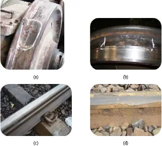
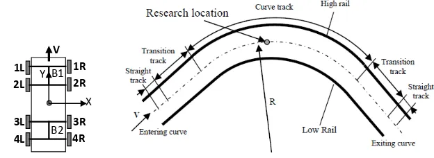
Figure 1 Damages of wheel and rail, (a) scratching wheel (b) porous wheel (c) wear rail (d) squashing rail (see online version for colours)
(a) (b)
(c) (d)
experimentally obtained two-dimensional model of the contact between wheel and rail, initial slope of creep force vs. creep curve depends on the characteristics of effective roughness (Bucher et al., 2002).
Developments of test equipment to wheel-rail and computer simulation are also performed. Matsumoto developing roller stand by using the scale 1/5 of the truck. This project is known as the ‘development of intelligent active wheel’. In this study discussed the characteristics of creep force of the roller rail and wheel on the various conditions of the contact (Matsumoto et al., 2002). Then, Iwnicki (2003) presented the forces arising on the wheel and rail contact on railway vehicles. These forces affect the behaviour of vehicles on the straight and curve track. The method is a common method to calculate these forces. ADAM/Rail Software was used (Iwnicki, 2003). Likewise, Polach (2003) developed a model to simulate the contact of rail wheels on wet or dry conditions. Developing method in this paper was possible to simulate the creep force accordance with measurements with variety of conditions, wet, dry, with pollutants, etc. (Polach, 2003). Meanwhile, the effect of different types of railway vehicle wheels on wheel rail contact force was studied by Johanson and Nielsen (2003). Vertical contact force was measured using a strain gauge. Strain gauge and accelerometer were placed on the rail and sleeper to measure the track response (Johanson and Nielsen, 2003). Furthermore, Baek et al. (2007) observed the effect of water lubrication of transient traction characteristics of the two roller contacts. Traction coefficient was measured in wet conditions, using a rolling sliding friction test machine with twin disc type, which can simulate the contact condition of the rail wheel low slip ratio and low rolling speed (Baek et al., 2007). Ghazavi and Taki (2008) modelled three-piece bogie using MATLAB and compared the L/V force with simulations using the software ADAMS/Rail.
Both models show similar results namely that the possibility of derailment occurred when the train enters the curve track and at the exit/end of the curve (Ghazavi and Taki, 2008). Then, the maximum stress and tangential force on the surface of the ellipse the contact area is influenced by the wheel rail contact dynamic load and creepages conducted by Xia et al. (2008). New method to measure the contact force between wheel and rail was developed by Matsumoto et al. The results showed that the new method is quite practical for monitoring contact force in the commercial line (Matsumotoa et al., 2008).
accurate in the contact area, contact pressure and deformation (Wiest et al., 2008). Soemantri et al. (2010) made formula to calculate contact dimension between wheel and rail. A more accurate result was obtained in determining the contact dimensions and maximum contact pressure. A finite element modelling was also performed to observe the variations of maximum contact stress in rail with respect to the change rail radius of curvature (Soemantri et al., 2010). Jin et al. (2009) utilised numerical method to analyse the effect of curving speed on the wear and contact stress of wheel and rail. The numerical method was a combination of Kalker theory, non-Hertzian rolling contacts, material wear model and the vertical and lateral dynamic model railway vehicle. The conclusion is very useful in the maintenance of the rail (Jin et al., 2009). Then, Gerlici and Lack (2010) discussed about the method of profile development of railway vehicle wheels. The method is based on the method of iteration. They developed a new profile with the given conditions. The results of the new profile were tested based on the distribution of normal stress and tangential stress which may affect to the fatigue behaviour of rail and wheel material. The result of the new profile gave better results than the wheel-rail standard (Gerlici and Lack, 2010).
Efforts to develop an analysis of the contact stress due to impact loads were performed by Wen et al. (2005). They analysed the contact stress due to impact on rail joint. Finite element method was used to simulate the contact behaviour of rail wheels on the rail joint. The material model was modelled by linear kinematic hardening. They also observed the influence of axle load and train speed on the contact force, stress and strain on the rail head when passing through the gap between the two railheads. The results showed axle load greater influence on the above parameters during the impact at a constant speed than the speed of the train. The research focused on the head of the rail (Wen et al., 2005). Then, Guaglianoa and Pau (2007) studied the contact pressure distribution in experiments using high-frequency ultrasonic wave reflections. It was provided on an internal crack in the wheel, and then it was compared with the pressure distribution according to Hertz theory. The goal was for the assessment of the influence of contact condition on the damage caused by an internal crack propagation (Guaglianoa and Pau, 2007). Parwata et al. (2008a) made simulations on the contact stress distribution due to rail impact load. They observed the influence of axle load, train speed, the difference misalignment of rails on rail joint. The simulation was performed using finite element software. Later in the year 2008 also, Parwata et al. (2008b) analysed the impact load on the wheel. Using the numerical approach, this phenomenon was modelled and simulated. They observed the influence of axle load, train speed, the difference of lateral misalignment of rails to the stress and strain on the wheel. The result showed the speed of the train provided the greatest influence and was more sensitive to stress. The axle load provided the greatest impact to the strain on the wheel (Parwata et al., 2008b).
1.1 Wheel and rail contact theory
The general formulation was used to produce the contacts force on the contact surface of wheel and rail as specified in Iwnicki (2006). When two rigid bodies are pressed together by a normal force, both surfaces undergo elastic deformation so that its contacts area is an ellipse. The shape and size of the contact area between two elastic bodies in static contact is given by Hertz (Garg and Dukkipati, 1984). The half-axis ellipse contact area can be calculated by the following equation:
Semiaxes in the longitudinal direction a:
(
)
1/3and semiaxes in the lateral direction b:
(
)
1/3Creepage phenomenon appears when two rigid bodies are pressed together and rolled to one another. Generally, the circumference speeds of both objects are not the same or there is relative velocity (slip). The importance of creepage in the dynamics of railway vehicle is presented by Carter (1926).
There are three types of creepage, namely: longitudinal creepage ξx, lateral creepage
ξy, and spin creepage ξsp that occurs in two bodies. Spin creepage is also defined as two
bodies rotating about an axis normal to the plane of contact area. Longitudinal creepage
ξx, lateral creepage ξy, and spin creepage ξsp respectively defined as follows (UM User’s
Manual, 2011):
lateral creepage y vy
v
0
Spin creepage n
sp v
ξ =Ω (8)
where vx, vy are the corresponding component of sliding velocity at the contact point on
the wheel relative to the rail, v0 is the longitudinal velocity of the wheelset, Ωn is the
projection of the wheel angular velocity o the normal to the rail at the contact point.
1.3 Creep forces
Creep force longitudinal Fx:
33
geometry, material properties and the normal force at the centre of the contact surface. Kalker creep coefficient is defined by the following:
11 ( ) 22
G combined shear modulus of rigidity wheel and rail materials,
Cij creepage and spin coefficients.
Kalker proposed combination elastic constants, which can be used as an approximation for the case of two bodies rolling with different elastic constants in determining the creepage and spin coefficients Cij. Let:
2 w R
Combined Poisson’s ratio of wheel and rail materials:
Gw shear modulus of rigidity of the wheel material
GR shear modulus of rigidity of the rail material
vw combined Poisson’s ratio of wheel
vW combined Poisson’s ratio of rail.
2 Modelling of railway vehicle and curve track
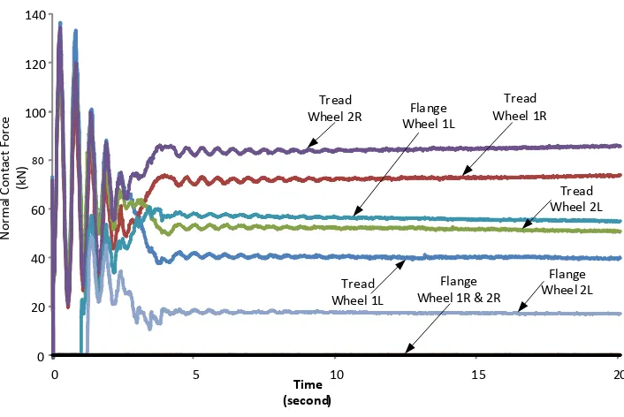
The simulation will be done by using universal mechanism software. The modelled bogie is a three piece type commonly used in freight trains. This type of bogie was used at Babaranjang train. The railways vehicle model consists of one carbody, four wheelsets, two bolsters, four sideframes, and eight wedges. Each of these components is considered as a mass associated each other with six degrees of freedom joint. Numbering starts from the front wheel of the vehicle, wheels 1L, wheel 1R, etc. which means wheel of wheelset 1 on the left and right respectively as in Figure 2, and so on for the next wheels. Bogie was also given a number B1 for the leading bogie and B2 for the trailing bogie.
The railway vehicle passed the right curve track with a radius of 200 m, the curve length is 250 m as shown in Figure 2. The vehicle entered the straight track along the 10 m and 30 m along the transition track, super elevation used is 0.010 m. Outer rail is a rail that serves to resist high centrifugal force during curving. Type profile wheel is used ORES 1002, whereas the rail profile type used are UIC 54. The speed varied from 32, 42, 52, 62, 72, 82 km/h and the mass of vehicle from 42, 47, 52, 57 and 62 ton.
Figure 2 Vehicle and curve track model
X
1L 1R 2L
3L 4L
2R
3R 4R V
Y B1
B2
3 Result and discussion
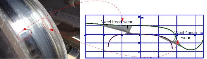
contact with the rail gauge face as shown in Figure 3. In this figure is also shown that the wheel on the right side (1R and 2R) has a normal force greater than the wheel on the left side (1L and 2L).
Figure 3 Normal forces of wheels in bogie 1 vs. time for curving speed 42 km/h, mass of vehicle 52 ton (see online version for colours)
0
Figure 4 Normal forces of wheels in bogie 2 vs. time for curving speed 42 km/h, mass of vehicle 52 ton (see online version for colours)
Figure 5 Wear in flange and tread wheel (see online version for colours)
The simulation results of bogie 2 are shown in Figure 4. At the beginning of the curve shows the movement of vehicle negotiation. This phenomenon is like that on bogie 1. Exiting the curve, hunting phenomenon of vehicle is smaller.
At the bogie 2, the greatest normal force is on the left side wheels. This force appears due to contact on the rail head. Furthermore, after 1:40 seconds contact on the flange started to ensue. So the normal force on the rail head down and gradually increasing the normal force on the flange. Figure 4 also showed that the left side wheels (3L and 4L) get the normal force greater than the right side wheels (3R and 4R). Meanwhile, the normal force contact on the wheel flange occurs only on the right side wheels (3R and 4R). This occurrence continues until the end of the curve.
In accordance with the Hertz equation (Parwata et al., 2008b; Iwnicki, 2006) that the normal force along with material properties and the principal of curvature of two bodies producing contact area at the interface of both bodies. Furthermore, the contact pressure is the normal force divided by this contact area. Together with the sliding distance, specific wear and hardness of the material, the normal force plays a very large influence on wear volume (Bolton and Clayton, 1984). This wear occurs in a contact area according to Hertz equation. On a curve track the contacts occurred at two points, namely at the tread and the flange section Thus, possibility of wear occurs at the contact location. Figure 5 shows the wear that occurs in the tread and wheel flange. Simulation also shows the location of the same contacts location.
3.1 Effect of curving speed on the characteristics of contact.
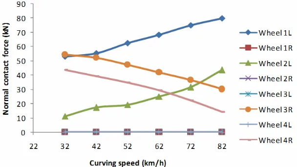
Characteristic contacts were observed when the vehicle runs as far as 195 m or running for 23.88 seconds, the location of this research as shown in Figure 2. The curve track has the circle curve radius 200 m and direction of track is clockwise. The mass of the vehicle was maintained constant at 52 tons. At the curve track, there are two points of contact that is on the rail head and flange face. At the head of the rail, increasing vehicle speed cause of increasing the normal force to the wheels that are on the left side (1L, 2L, 3L, and 4L).
On the flange there is a difference tendency of each wheel. Wheels on the left side of the bogie 1 (1L and 2L) showed a tendency to increase with increasing of curving speed. While the wheels on the right side bogie 2 (3R and 4R wheels) tend to decrease with increasing speed. Even the wheels 1R, 2R, 3L and 4L are not in contact with the rails so that the normal force is zero, as shown in Figure 7.
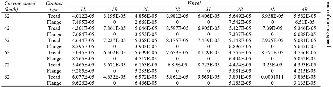
Meanwhile, the relationship between curving speed and an area on each wheel are presented in Table 1. This contact area is the total area without involving the area of stick and slip. It appears that the wheels on the left side increased with increasing of curving speed. Instead, contact area on the wheels on the right side tends to decrease. The average of increasing the contact area on the left side on the tread section, from curving speed 32 km/h to 82 km/h is 5.06 × 10⁻⁶ m2. Meanwhile, the right side of wheel was reduced by –5.12 × 10⁻⁶ m2.
Figure 6 Normal forces vs. curving speed at tread region (see online version for colours)
Effect of curvi
n
g speed and
mas
s of railway vehicle
26
Contact
ar
ea
for
each
of
curving
s
p
eed
Curving speed (km/h)
Contact type
Wheel
1L 1R 2L 2R 3L 3R 4L 4R
32 Tread 4.012E-05 8.195E-05 4.856E-05 8.981E-05 6.406E-05 5.649E-05 6.938E-05 5.582E-05
Flange 7.495E-05 0 2.668E-05 0 0 7.542E-05 0 6.51E-05
42 Tread 4.301E-05 7.861E-05 5.046E-05 8.597E-05 6.905E-05 5.427E-05 7.39E-05 5.346E-05
Flange 7.684E-05 0 3.555E-05 0 0 7.337E-05 0 6.088E-05
52 Tread 4.644E-05 7.237E-05 5.368E-05 8.175E-05 7.439E-05 5.148E-05 7.925E-05 5.081E-05
Flange 8.295E-05 0 3.903E-05 0 0 6.896E-05 0 5.632E-05
62 Tread 5.045E-05 6.502E-05 5.699E-05 7.659E-05 8.129E-05 4.755E-05 8.571E-05 4.756E-05
Flange 8.765E-05 0 4.517E-05 0 0 6.404E-05 0 5.052E-05
72 Tread 5.466E-05 5.671E-05 6.163E-05 6.89E-05 8.723E-05 4.424E-05 9.25E-05 4.393E-05
Flange 9.285E-05 0 5.235E-05 0 0 5.881E-05 0 4.215E-05
82 Tread 6.077E-05 4.632E-05 6.572E-05 5.861E-05 9.569E-05 3.801E-05 0.0001011 3.865E-05
For the flange section, increasing of contact area occurred on the wheels 1L and 2L. Average of increasing is 2.96 × 10⁻⁶ m2, while for the wheel on the right side the contact area decreased by 2.87 × 10⁻⁶ m2.
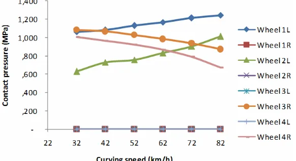
Figure 8 Contact pressure vs. curving speed at tread section (see online version for colours)
Effect of curving speed to the contact pressure is shown in Figure 8 for the tread contact and Figure 9 for the flange contacts. In general, contact pressure increased on the tread and flange region and contrary to the wheel on the right side. Wheel 2L receive the greatest contact pressure on tread contact, while the greatest contact pressure on the flange section received by wheel 1L. The average of tendency of increased pressures for the wheels come into contact is 5.75 × 10⁶, while on the flange 5.5 × 10⁶.
3.2 Effect of vehicle mass on the characteristics of contacts
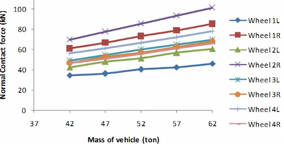
Effect of vehicle mass on the normal force is shown in Figure 10. It shows that the mass of vehicle increased the normal force in the tread all of wheels. Most of the normal force is received by the wheels 2R. Surely this will have a significant influence on the pressure and contact stress. The greatest normal force is received by wheel flange 1L. Thus, it can be predicted that the wheel 1L will be wear more frequently than the other wheels. The flange contact did not occur on the wheel flanges 1R, 2R, 3L and 4L as shown in Figure 11.
Figure 10 Normal force vs. mass of vehicle at tread region (see online version for colours)
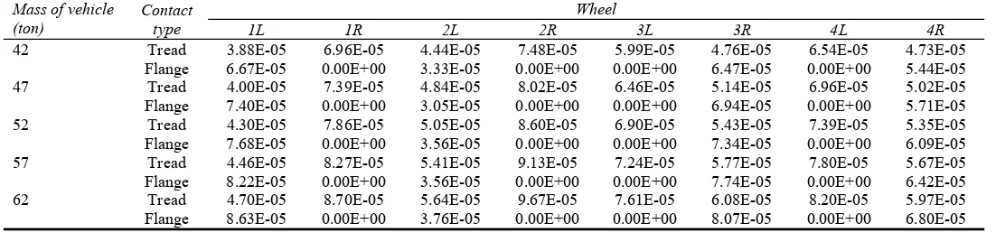
At the contact, the relations between vehicle mass and contact area on each wheel are shown in Table 2. As same as Table 1, the contact area is the total area. It appears that all of wheels have increased the area by increasing the mass of the vehicle. Increasing of the average contact area on the tread for all-wheels is 3.68 × 10⁶ m2. It was due to the increasing of normal force received by the surface contacts. The greatest of contact area at the flange region occurred on the wheels 1L. While the wheels 1R, 2R, 3L and 4L are not in contact on the flange. Increasing of the contact area for the wheel is 3.34 × 10⁶ m2.
I.M.
P
a
rw
at
a e
t al
.
Contact
ar
ea
for
each
of v
ehi
cle
m
as
s
Mass of vehicle (ton)
Contact type
Wheel
1L 1R 2L 2R 3L 3R 4L 4R
42 Tread 3.88E-05 6.96E-05 4.44E-05 7.48E-05 5.99E-05 4.76E-05 6.54E-05 4.73E-05
Flange 6.67E-05 0.00E+00 3.33E-05 0.00E+00 0.00E+00 6.47E-05 0.00E+00 5.44E-05
47 Tread 4.00E-05 7.39E-05 4.84E-05 8.02E-05 6.46E-05 5.14E-05 6.96E-05 5.02E-05
Flange 7.40E-05 0.00E+00 3.05E-05 0.00E+00 0.00E+00 6.94E-05 0.00E+00 5.71E-05
52 Tread 4.30E-05 7.86E-05 5.05E-05 8.60E-05 6.90E-05 5.43E-05 7.39E-05 5.35E-05
Flange 7.68E-05 0.00E+00 3.56E-05 0.00E+00 0.00E+00 7.34E-05 0.00E+00 6.09E-05
57 Tread 4.46E-05 8.27E-05 5.41E-05 9.13E-05 7.24E-05 5.77E-05 7.80E-05 5.67E-05
Flange 8.22E-05 0.00E+00 3.56E-05 0.00E+00 0.00E+00 7.74E-05 0.00E+00 6.42E-05
62 Tread 4.70E-05 8.70E-05 5.64E-05 9.67E-05 7.61E-05 6.08E-05 8.20E-05 5.97E-05
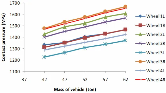
Figure 12 Contact pressure vs. mass of vehicle at tread (see online version for colours)
Figure 13 Contact pressure vs. mass of vehicle at flange (see online version for colours)
Figure 12 shows the relation between contact pressure and the mass of vehicle for the contact that occurs on the wheel tread. It appears that all off wheel, the contact pressure increased due to increasing of vehicle mass. The average of tendency is 8.13 × 10⁶. It is for all exposed wheels and wheels 3R get the greatest contact pressure. While vehicle mass only increased the contact pressure on the wheels 1L, 2L, 3R and 4R at flange area.
4 Conclusions
Base on the above explanation can be concluded: As the vehicle passed the curve track, it occurred of movement load due to centrifugal force. Consequently, the contact occurred in the flange. Increased curving speed and mass of vehicle causes at the flange area of wheels 1L always produced the greatest of normal contact force and contact pressure.
of curving speed. Meanwhile, on the flange increased curving speed gives greater influence than the increased vehicle mass.
Acknowledgements
The authors would like to thank the PT. INKA (Railway Industry) to give us using UM software for this simulation. The authors would also like to thank Dr. Yunendar and Moch Athur for the technical assistance.
References
Baek, K.S., Kyogoku, K. and Nakahara, T. (2007) ‘An experimental investigation of transient traction characteristics in rolling-sliding wheel/rail contacts under dry-wet conditions’, Wear, Vol. 263, Nos. 1–6, pp.169–179.
Beagley, T.M. (1976) ‘Severe wear of sliding/rolling contacts’, Wear, Vol. 36, No. 3, pp.317–335. Beek, A.V. (2006) Advanced Engineering Design Life Time Performance and Reliability, TU Delft
Publisher, Netherland.
Bhaskar, A., Johnson, K.L., Wood, G.D. and Woodhouse, J. (1997a) ‘Wheel-rail dynamics with closely conformal contact part 1: Dynamic modeling and stability’, Proceedings of the Institution of Mechanical Engineers, ProQuest Science Journals, Vol. 211, No. 1, p.11. Bhaskar, A., Johnson, K.L. and Woodhouse, J. (1997b) ‘Wheel-rail dynamics with closely
conformal contact part 2: Forced response, result and conclusion’, Proceedings of the Institution of Mechanical Engineers, ProQuest Science Journals, Vol. 211, No. 1, p.27. Bolton, P.J. and Clayton, P. (1984) ‘Rolling-sliding wear damage in rail and tyre steels’, Wear,
Vol. 93, pp.145–165.
Bucher, F., Knothe, K. and Theiler, A. (2002) ‘Normal and tangential contact problem of surfaces with measured roughness’, Wear, Vol. 253, Nos. 1–2, pp.204–218.
Carter, F.W. (1926) ‘On the action of locomotive driving wheel’, Proc. R.Soc. London, Ser. A, Vol. 112, pp.151–157.
Chiverst, T.C. and Radcliffe, S.J. (1987) ‘The variation of lateral forces as a function of alignment for a cylindrical wheel rolling on a rail’, Tribology International, Vol. 20, No. 5, pp.234–236. Clayton, P. (1995) ‘Predicting the wear of rails on curves from laboratory data’, Wear, Vol. 181,
Part 1, pp.11–19.
Garg, V.K. and Dukkipati, R.V. (1984) Dynamics of Railway Vehicle Systems, pp.106–107, Academic Press Canada, Ontario.
Gerlici, J. and Lack, T. (2010) ‘Contact geometry influence on the rail/wheel surface stress distribution’, Procedia Engineering, Vol. 2, pp.2249–2257.
Ghazavi, M.R. and Taki, M. (2008) ‘Dynamic simulations of the freight three-piece bogie motion in curve’, Vehicle System Dynamics, Vol. 46, No. 10, pp.955–973.
Guaglianoa, M. and Pau, M. (2007) ‘Analysis of internal cracks in railway wheels under experimentally determined pressure distributions’, Tribology International, Vol. 40, No. 7, pp.1147–1160.
Iwnicki, S. (2003) ‘Simulation of wheel-rail contact forces’, Fatigue Fract Engng Mater Struct., Vol. 26, No. 10, pp.887–900.
Jin, X., Xiao, X., Wen, Z., Guo, J. and Zhu, M. (2009) ‘An investigation into the effect of train curving on wear and contact stresses of wheel and rail’, Tribology International, Vol. 42, No. 3, pp.475–490.
Johansson, A. and Nielsen, J.C.O. (2003) ‘Out-of-round railway wheels-wheel-rail contact forces and track response derived from field test and numerical simulations’, Proceedings of the Institution of Mechanical Engineers, Vol. 217, No. 2, pp.135–146.
Lenkiewicz, W. (1969) ‘The sliding friction process effect of external vibrations’, Wear, Vol. 13, No. 2, pp.99–108.
Matsumoto, A. et al. (2002) ‘Creep force characteristics between rail and wheel on scaled model’,
Wear, Vol. 253, Nos. 1–2, pp.199–203.
Matsumoto, A., Sato, Y., Nakata, M., Tanimoto, M. and Qi, K. (1996) ‘Wheel-rail contact mechanics at full scale on the test stand’, Wear, Vol. 191, Nos. 1–2, pp.101–106.
Matsumotoa, A. et al. (2008) ‘A new measuring method of wheel-rail contact forces and related considerations’, Wear, Vol. 265, Nos. 9–10, pp.1518–1525.
Parwata, I.M., Brodjonegoro, S.S. and Puja, I.W. (2008a) ‘Contact stress distribution in rail due to Impact while wheel roll over a rail joint with rail misalignment in lateral direction’, Prosiding Seminar Nasional Teknologi Simulasi IV UGM, Yogyakarta, pp.508–514.
Parwata, I.M., Schipper, D.J., Puja, I.W. and Brodjonegoro, S.S. (2008b) ‘Contact stress distribution in wheel due to impact while wheel roll over a rail joint with rail misalignment in lateral direction’, Prosiding Seminar Nasional Aplikasi Sains dan Teknologi, Kampus IST AKPRIND, Yogyakarta, pp.1–8.
Pau, M. (2003) ‘Estimation of real contact area in a wheel-rail system by means of ultrasonic waves’, Tribology International, Vol. 36, No. 9, pp.687–690.
Pau, M., Aymerich, F. and Ginesu, F. (2000) ‘Ultrasonic measurements of nominal contact area and contact pressure in a wheel rail system’, Proceedings of the Institution of Mechanical Engineers, Vol. 214, No. 4, pp.231–243.
Pau, M., Aymerich, F. and Ginesu, F. (2002) ‘Distribution of contact pressure in wheel-rail contact area’, Vol. 253, Nos. 1–2, pp.265–274.
Polach, O. (2003) ‘Creep force in simulations of traction vehicles running on adhesion limit’, 6th International Conference on Contact Mechanics and Wear of Rail/Wheel Systems in Gothenburg, Sweden, 10–13 June, pp.279–285.
Soemantri, S., Puja, I.W., Budiwantoro, B., Parwata, I.M. and Schipper, D.J. (2010) ‘Solutions to Hertzian contact problem between wheel and rail for small radius of curvature’, Journal of Solid Mechanics and Materials Engineering, Vol. 4, No. 6, pp.669–677.
UM User’s Manual (2011) ‘Simulation of railway vehicles’,
http://www.umlab.ru/download/50/eng/08_um_loco.pdf (accessed on 31 March 2011). Wen, Z., Jin, X. and Zhang, W. (2005) ‘Contact-impact stress analysis of rail joint region using the
dynamic finite element method’, Wear, Vol. 258, pp.1301–1309, Nos. 7–8.
Wiest, M., Kassac, E., Davesa, W., Nielsen, J.C.O. and Ossberger, H. (2008) ‘Assessment of methods for calculating contact pressure in wheel-rail/switch contact’, Wear, Vol. 265, Nos. 9–10, pp.1439–1445.