DISSERTATION – RC143505
Cyclic Behaviour of Slab-Column Connections
using the Engineered Cementitious Composite
ASDAM TAMBUSAY 3113 301 017
SUPERVISORS:
Prof. Ir. Priyo Suprobo M.S., Ph.D. Dr. Eng. A. Arwin Amiruddin, S.T., MT.
DOCTORAL PROGRAMME
FIELD OF STUDY STRUCTURAL ENGINEERING DEPARTMENT OF CIVIL ENGINEERING
FACULTY OF CIVIL ENGINEERING AND PLANNING INSTITUT TEKNOLOGI SEPULUH NOPEMBER SURABAYA
DECLARATION
I, Asdam Tambusay, hereby declare that the following thesis has been composed by me and expressed in my own words, that the work has been carried out by myself, and that it has not been presented in any previous application for a higher
Perilaku Siklik Hubungan Pelat-Kolom Menggunakan Material Engineered Cementitious Composite
Nama Mahasiswa : Asdam Tambusay
NRP : 3113 301 017
Promotor : Prof. Ir. Priyo Suprobo MS., Ph.D.
Co-Promotor : Dr. Eng. A. Arwin Amiruddin, ST., MT.
:
ABSTRAK
Penyelidikan eksperimen di laboratorium dilakukan untuk mempelajari perilaku struktur hubungan pelat-kolom akibat kondisi pembebanan yang relatif tinggi. Dalam penelitian ini, alternatif baru diusulkan untuk meningkatkan respons struktur hubungan pelat-kolom. Alternatif ini menggunakan jenis material yang berorientasi semen yakni engineered cementitious composite (ECC) bersama dengan penggunaan elemen drop panel pada bagian sambungan yang berfungsi sebagai penebalan lokal. Untuk menunjukkan penerapan alternatif yang diusulkan, tiga jenis benda uji diuji terhadap beban gravitasi konstan dan beban lateral siklik. Benda uji tersebut merupakan benda uji skala 1:2 yang juga merupakan representasi model interior hubungan pelat-kolom pada prototipe bangunan flat slab. Semua beda uji didesain tanpa menggunakan tulangan geser pada pelat, namun rasio tulangan lenturnya didesain cukup rendah dengan nilai berkisar 0.01. Hal ini dilakukan untuk menjamin bahwa benda uji akan berperilaku dalam kondisi under-reinforced sehingga mengizinkan tulangan lentur pada pelat mengalami pelelehan terlebih dahulu sebelum kegagalan beton pada benda uji. Jumlah tulangan pelat dan kolom yang digunakan pada benda uji adalah tipikal untuk setiap spesimen. Benda uji kontrol, di sini sebut sebagai benda uji pertama, di fabrikasi menggunakan beton konvensional, sedangkan benda uji kedua dan ketiga di fabrikasi dengan kombinasi material ECC dan beton konvensional. Pada benda uji kedua dan ketiga, ECC hanya dicor pada daerah penebalan lokal (drop panel). Mutu beton konvensional dan ECC pun didesain relatif sama. Semua benda uji dibebani dengan skenario beban siklik lateral yang sama. Pengecualian hanya terjadi pada penentuan nilai rasio beban gravitasi (GSR) di mana benda uji pertama, kedua dan ketiga memiliki GSR 0,08, 0,05, dan 0,25 secara berurutan. Perbedaan nilai rasio beban gravitasi dilakukan untuk mengetahui kinerja ECC dalam menahan beban gravitasi yang cukup signifikan.
untuk menjelaskan mekanisme gaya-gaya dalam yang bekerja pada benda uji hubungan pelat-kolom ketika dibebani beban gravitasi dan beban lateral siklik, sebagai contoh, distribusi tegangan utama pada pelat, atau mekanisme pembentukan sendi plastis.
Berdasarkan hasil eksperimental, hal ini jelas terbukti bahwa semua benda uji mengalami kegagalan dalam kondisi lentur. Hal ini terlihat dari sebagian besar retak yang terjadi pada daerah pelat merupakan retak yang tegak lurus dengan arah pembebanan, di mana retak ini pun merambat selebar lebar pelat. Di sisi lain, terlihat pula bahwa benda uji kedua menunjukkan kenaikan kapasitas beban lateral dua kali lipat lebih besar daripada benda uji kontrol. Di samping itu, setelah kenaikan rasio simpangan 3,5%, benda uji kedua tidak mengalami penurunan kekuatan, sedangkan benda uji kontrol menunjukkan kehilangan kekuatan lateral yang signifikan pada rasio simpangan yang sama. Berdasarkan hasil pengamatan pada benda uji ketiga, jelas terlihat bahwa respons benda uji ini hampir menyerupai benda uji kedua meskipun dibebani dengan rasio beban gravitasi menengah. Berdasarkan evaluasi kriteria ACI 374.1-05, benda uji kedua dan ketiga secara umum memenuhi persyaratan sebagai struktur tahan gempa, meskipun benda uji yang diusulkan belum layak direkomendasikan untuk diterapkan pada kategori desain seismik IV karena kekakuan awal yang tidak memadai.
Berdasarkan hasil analisis numerik, hal ini menunjukkan bahwa kurva histerisis dan backbone yang diperoleh pada pengujian eksperimen menunjukkan tren yang sama dengan kurva histerisis dan backbone analisis numerik. Hal lain juga menunjukkan bahwa nilai tegangan utama pada pelat masih lebih rendah dari kuat tekan beton, sehingga mengimplikasikan bahwa benda uji belum mengalami crushing pada beton. Hal ini juga dapat diasosiasikan dengan fenomena yang terjadi selama pengujian eksperimen, di mana semua benda uji tidak mengalami crushing bahkan sampai pada akhir pembebanan.
Cyclic Behaviour of Slab-Column Connections using the Engineered Cementitious Composite
Student’s Name : Asdam Tambusay
Student’s ID : 3113 301 017
Supervisor : Prof. Ir. Priyo Suprobo MS., Ph.D.
Co-Supervisor : Dr. Eng. A. Arwin Amiruddin, ST., MT
ABSTRACT
An experimental investigation has been undertaken to study the behaviour of slab-column connections subjected to high loading conditions. A novel alternative to improve the structural response of slab-column connections is proposed. The proposed alternative employs the use of a cement-based engineered cementitious composite (ECC) material along with the addition of drop panel attached to the connection. To demonstrate the applicability of this alternative, the three test specimens were tested under combined gravity and cyclic lateral loading. These specimens were half-scale representations of interior slab-column connections in a prototype flat slab building. All test specimens had no shear reinforcement provided in the slab, yet the longitudinal reinforcement ratio was designed relatively low, with the ratio approximately 0.01. This is to ensure that the specimens were in under-reinforced section thereby allowing the reinforcing bars to yield prior to specimen failure. The amount of reinforcing bars used to make the specimen was typical to each of test specimens. The control specimen, hereinafter referred to as the first specimen, was cast using conventional concrete, while other second and third specimen were cast with ECC and conventional concrete. In both latter specimens, ECC was only placed within the local thickening area. The grades of conventional concrete and ECC were also designed similarly. All specimens were subjected to similar cyclic displacement routine. The only exception lies on the application of gravity shear ratio (GSR) in which the value of GSR of first, second, and the third specimen was 0.08, 0.05, and 0.25 respectively. The influence of the different range of gravity shear ratio was examined to assess the performance of ECC resisting the intermediate gravity load.
Apart from the experimental investigation, a number of nonlinear finite element simulations have also been included in this study for comparative purposes with regard to the experimental results. As such, three different finite element software packages have been used to perform the nonlinear analysis. In addition to the experimental verification, further analysis has been carried out to lucidly explain the internal mechanisms of slab-column connections when being subjected to combined gravity and cyclic lateral loading, for instance, the principal stress distribution alongside the slab, and the governance of plastic hinge zone.
to loading direction which also extends towards the entire width of the slab. It is also shown that the second specimen exhibits better behavioural response than control specimen whereby the lateral load capacity is nearly twice higher than the first specimen. Furthermore, upon the drift ratio of 3.5%, the second specimen does not undergo strength degradation, whereas in the control specimen the prominent loss of strength is apparent at 3.5% drift level, implying the response is on the verge of failure. With regard to the results from the third specimen, it is shown the overall behaviour resembles the response of the second specimen despite being subjected to intermediate gravity loading. In accordance with the evaluation of acceptance criteria, the second and third specimen generally comply the requirements as an earthquake proof and resistant structure. The only exception is that the proposed structure is not yet recommended to be applied in seismic design category IV due to inadequate initial stiffness provided by the structure.
In terms of numerical results, it is shown that the hysteretic and backbone curves obtained from experimental tests are in good agreement with the hysteretic and backbone curves obtained from the nonlinear finite element analysis. It is also shown that the magnitude of principal stress is still less than the compressive stress of concrete, owing to the fact that the specimens do not undergo concrete crushing. This also can be associated with the phenomenon captured in the experimental investigation where all the test specimens did not experience concrete crushing up to the final stage of loading.
ACKNOWLEDGEMENTS
This thesis represents not only my work behind the desk, but it is also a milestone in years of study at ITS and specifically within the Laboratory of Concrete and Building Materials. Despite my short of experiences throughout these years, I have learned a multitude of knowledge thereby helping me be the person who has a grounded mindset. It has also been an incredible journey for me because I have been given many opportunities beyond my expectation.
First and foremost, I wish to thank my advisor, Professor Priyo Suprobo, director of the Laboratory of Concrete and Building Materials at ITS. He has been truly supportive since the first day I began working with him. Throughout these years, he provided me with his wisdom, enthusiasm, inspiration, and invaluable advice. His profound and broad knowledge, continuous encouragement, inspiring ideas, keen instruction and supervision, and meticulous revisions massively helped me to achieve this work. I have learned a lot through my wealth of experience with him on his excellent academic, professional and personal levels. This dissertation would not be possible and fruitful without his excellent guidance and encouragement throughout the entire process of my study.
I also would like to express my sincere gratitude to my second advisor, Faimun PhD, for being such a supportive person. His understanding of structural engineering has helped me a lot to manage to complete this thesis. His suggestion, criticism and constructive comments have been invaluable in the preparation of this thesis.
My sincere gratitude also goes to my third advisor, Dr. Arwin Amiruddin, for devoting his time to my experimental program at the University of Hasanuddin. He provided me fundamental insight based on his experience working in the laboratory.
Special thanks are due to other members of the committee, Professor Iswandi Imran, Handayanu PhD, and Endah Wahyuni PhD, for their time, criticism, invaluable and qualified review, and also the suggestions of the materials of this thesis.
I wish to acknowledge the Ministry of Research, Technology, and Higher Education of the Republic of Indonesia for the financial support throughout my study under the scheme of Master-Doctor Internship Programme (PMDSU) Scholarship.
I also wish to acknowledge all the supports provided by WIKA Beton Tbk., and for putting this research as a priority, particularly during the fabrication of the specimens. My genuine thanks also go to PT. Hanil Jaya Steel for supplying the reinforcing steel.
I would like to extend my deepest appreciation and gratitude to the Laboratory of Structure and Materials at Hasanuddin University for providing technical and administrative services during my experimental investigation.
My genuine gratitude is also extended to my very kind host-supervisor, Dr. Benny Suryanto; an assistant professor at Heriot-Watt University in Edinburgh whom I have been working with. He provided me with his broad knowledge and understanding of concrete mechanics. I have found his enthusiasm and work ethic inspiring.
I also wish to thank Jonathon Luke Fox and Danah Saraireh for being such good mates when I was in the UK. They gave me the warmest welcome, and the helped me a lot throughout my programme. I was so lucky to have such opportunity to meet them in person.
I would like to express my sincere gratitude to my friendly academic peers at Master Program in the field of Structural Engineering at ITS, for creating the warmest environment throughout these years.
TABLE OF CONTENTS
CHAPTER 1 INTRODUCTION………. 1
1.1. Background………... 1
1.2. Research Significance………... 5
1.3. Research Objectives……….. 6
1.4. Scope of Research………. 7
1.5. Hypothesis Adopted……….. 8
CHAPTER 2 LITERATURE REVIEW………... 11
2.1. Flat Slab Structural System………... 11
2.2. Mechanics of Slab-Column Connections……….. 13
2.3. Failure Mode of Slab-Column Connection………... 15
2.4. General Setups of Slab-Column Connections Tested under Gravity and Lateral and Loading………... 16
2.5. Influence of Flexural Reinforcement Ratio……….. 17
2.6. The Use of Drop Panel in Flat Slab Structure……….. 19
2.7. Engineered Cementitious Composite (ECC)……… 24
2.8. Acceptance Criteria for Earthquake Proof and Resistant Structures 29 2.9. Ductility……… 31
2.10. Previous Experimental Investigation on the Cyclic Behaviour of Slab-Column Connections (Prawatwong et al. 2008)……….. 32
CHAPTER 3 EXPERIMENTAL PROGRAMME……… 37
3.1. Analytical Design of Shear Stress in the Slab……….. 37
3.2. Specimen Design……….. 39
3.3. Specimen Preparation………... 43
3.3.1. Reinforcing cage and strain gauge installation………. 43
3.3.2. Casting and curing……… 45
3.4. Mix Design of Concrete and ECC……… 47
3.5. Mechanical Properties of Material……… 50
3.5.1. Properties of normal concrete…….……….. 50
3.5.2. Properties engineered cementitious composite………. 51
3.5.3. Properties of reinforcing bar………. 54
3.6. Experimental Activities……… 56
3.6.1. Test setup……….. 56
3.6.2. Pre-test activities………... 58
3.7. Loading protocol………... 59
3.8. Instrumentation………. 61
3.9. Monitoring and Data Acquisition………. 63
3.10. Evaluation of Test Results……… 64
CHAPTER 4 EXPERIMENTAL RESULTS AND DISCUSSION….. 67
4.1. Load-Drift Relationship and Cracking Behaviour……… 67
4.2. Analytical Evaluation Based on Design Codes……… 76
4.3. Connection Lateral Drift Capacity……… 79
4.4. Evaluation of Acceptance Criteria……… 81
4.4.1. Strength degradation………. 81
4.4.2. Concept of strong column/weak beam……….. 83
4.4.3. Initial stiffness………... 85
4.4.4. Stiffness degradation………. 87
4.4.5. Energy dissipation………. 89
4.5. Slab Flexural Reinforcement Strain Readings……….. 92
CHAPTER 5 FINITE ELEMENT ANALYSIS………. 99
5.1. Work Package 1 – ABAQUS……… 99
5.1.2. Element model……….. 100
5.1.3. Material properties……… 100
5.1.4. Mesh and boundary conditions………. 107
5.1.5. Loading scenario………... 107
5.1.6. The solution of nonlinear problems……….. 108
5.1.7. Results and discussion of ABAQUS……… 113
5.2. Work Package 2 – SAP2000………. 122
5.2.1. Overview………... 122
5.2.2. Hysteretic rules………. 124
5.2.3. Parameters controlling hysteretic response………... 126
5.2.4. Developed model of slab-column connection using SAP2000……. 126
5.2.5. Results and discussions of SAP2000……… 129
5.3. Work Package 3 – ZEUS NL……… 131
5.3.1. Overview………... 131
5.3.2. Material models……… 132
5.3.3. Element model……….. 134
5.3.4. Analytical model of slab-column connection using ZEUS-NL…… 135
5.3.5. Results and discussion of ZEUS-NL……… 135
5.4. Summary of Numerical Analyses………. 137
5.5. Further Analysis of Prototype Slab-Column Connections………... 138
CHAPTER 6 CONCLUSIONS AND RECOMMENDATIONS…….. 143
6.1. Conclusions………... 143
6.2. Recommendations for Future Research……… 146
REFERENCES………. 149
APPENDIX A: PRELIMINARY DESIGN OF SPECIMEN S1…… 159
APPENDIX B: PRELIMINARY DESIGN OF SPECIMEN S2…… 165
APPENDIX C: PRELIMINARY DESIGN OF SPECIMEN S3…… 171
LIST OF FIGURES
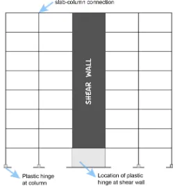
Figure 1.1 The location of plastic hinge mechanisms in the flat slab
structure as flexural moment resisting frame……… 8
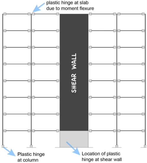
Figure 1.2 The location of plastic hinge mechanisms in the flat slab structure as special moment resisting frame……… 9
Figure 2.1 Typical form of flat slab structure………... 11
Figure 2.2 Illustration of joint location of slab-column connections……… 12
Figure 2.3 Critical region around slab-column connection………... 13
Figure 2.4 Critical section (perimeter) of slab-column connection……….. 14
Figure 2.5 Transfer of uniform gravity load unbalanced moment within the critical section: (a) uniform shear stress due to gravity load; (b) eccentric shear stress due to unbalanced moment; (c) total shear stress………. 14
Figure 2.6 Schematic model for shear and moment transfer of slab-column connection……… 15
Figure 2.7 Formation of flexural cracks due to lateral load……….. 16
Figure 2.8 Drop panel members in flat slab structure………... 19
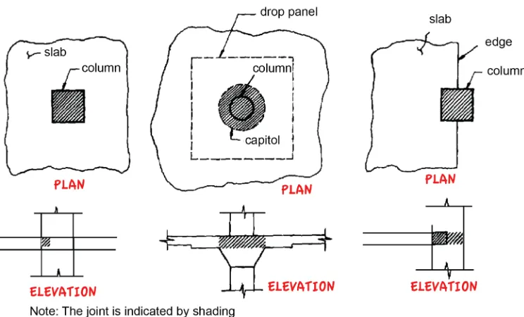
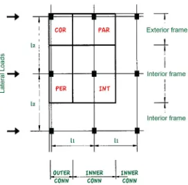
Figure 2.9 Four types of connections in flat slab system………... 22
Figure 2.10 Effective slab widths: (a) termed as strength; (b) termed as stiffness………. 23
Figure 2.11 Uniaxial tensile stress-strain relationship and crack widths of ECC with the additional information of typical tensile response of conventional concrete to facilitate direct comparison……….. 26
Figure 2.12 Pre-cracked ECC plates: (a) testing procedure; (b) crack patterns of selected plates within constant moment span at failure……… 28
Figure 2.13 Quantities used in evaluating acceptance criteria………. 31
Figure 2.14 Unacceptable hysteretic behaviour………... 31
Figure 3.2 Schematic geometry of test specimen [unit in millimetre]: (a)
top view; (b) longitudinal direction (x-axis)………. 41
Figure 3.3 Reinforcement layouts [unit in millimetre]: (a) slab top reinforcement bars; (b) slab bottom reinforcement bars; (c) longitudinal and web reinforcement of column……… 42
Figure 3.4 Chronological process of reinforcing cage, starting from the fabrication to the adjustment in the formwork (steel mould) along with the installation of strain gauges……….. 44
Figure 3.5 Phase of casting the specimen with ECC………. 46
Figure 3.6 Packing of specimen………. 47
Figure 3.7 Setup of direct tensile test of ECC dog-bone shape………. 50
Figure 3.8 Compressive stress-strain relationship of ECC cubes………….. 53
Figure 3.9 Tensile stress-strain relationship of ECC dog-bone shapes……. 54
Figure 3.10 Tensile stress-strain response of reinforcing bars……… 55
Figure 3.11 Test set up of slab-column connection………. 56
Figure 3.12 Schematic testing configurations [unit in millimetre]: (a) side view in longitudinal direction; (b) top view………. 57
Figure 3.13 Uplift technique for test specimen……… 59
Figure 3.14 Lateral displacement routine……… 61
Figure 3.15 Location of strain gauges and LVDTs: (a) strain gauges at top slab reinforcing bars; (b) strain gauges at bottom slab reinforcing bars; (c) strain gauges of column and LVDTs seen from longitudinal direction; (d) strain gauges of column observed from transversal direction………. 62
Figure 3.16 Scheme of experimental test and data acquisitions……….. 63
Figure 4.1 Load-drift relationship of specimen S1: (a) hysteretic behaviour with additional photo of final crack pattern, (b) traditional hand-drawn crack pattern observed on the top and bottom surface of the slab……….. 68
drawn crack pattern observed on the top and bottom surface of
the slab……….
Figure 4.3 Load-drift relationship of specimen S3: (a) hysteretic behaviour with additional photo of final crack pattern, (b) traditional
hand-drawn crack pattern observed on the top and bottom surface of
the slab……….. 74
Figure 4.4 Comparison of backbone (envelope) curves of all specimens in
each cycle of the loading sequence………... 75
Figure 4.5 Drift capacity versus gravity shear ratio of slab-column connections using drop panel with continued slab
reinforcements………... 80
Figure 4.6 Illustrated graph for defining the strength degradation for all
specimens: (a) specimen S1, (b) specimen S2, (c) specimen S3.. 82
Figure 4.7 Illustrated graph for describing the stiffness degradation for all
specimens: (a) specimen S1, (b) specimen S2, (c) specimen S3.. 88
Figure 4.8 Illustrated graph of the parallelogram of ideal energy
dissipation for all specimens: (a) specimen S1, (b) specimen S2,
(c) specimen S3………. 91
Figure 4.9 1 Longitudinal strain profiles of specimen S1 measured in the slab reinforcing bars: (a) top reinforcing bars, (b) bottom
reinforcing bars………. 93
Figure 4.10 Longitudinal strain profiles of specimen S2 measured in the slab reinforcing bars: (a) top reinforcing bars, (b) bottom
reinforcing bars………. 95
Figure 4.11 Longitudinal strain profiles of specimen S3 measured in the slab reinforcing bars: (a) top reinforcing bars, (b) bottom
reinforcing bars………. 97
Figure 5.1 Element types of FE model: (a) C3D8R linear brick element for concrete; (b) T3D2 truss element for reinforcement bars………. 99
Figure 5.2 Parameters of concrete damage plasticity model: (a)
of concrete; (c) typical damage evolution of concrete and ECC;
(d) tensile response of ECC………..
Figure 5.3 Assumed average stress-strain relationship of reinforcements
embedded in concrete………... 105
Figure 5.4 Finite element mesh and boundary conditions (unit is in
millimetre)……… 106
Figure 5.5 Loading etiquette in numerical simulation using displacement
control method……….. 107
Figure 5.6 First equilibrium iteration in an increment………... 109
Figure 5.7 Second equilibrium iteration in an increment………... 112
Figure 5.8 Predicted load-drift relationship of specimen S1: (a) hysteretic
loop and (b) backbone curves………... 113
Figure 5.9 Predicted load-drift relationship of specimen S2: (a) hysteretic
loop and (b) backbone curves………... 113
Figure 5.10 Predicted load-drift relationship of specimen S3: (a) hysteretic
loop and (b) backbone curves………... 113
Figure 5.11 Principal stress distribution of specimen S1: (a) stress at the slab top surface in the positive loading, (b) stress at the slab
bottom surface in the positive loading, (c) stress at the slab top
surface in the negative loading, and (d) stress at the slab bottom
surface in the negative loading………. 116
Figure 5.12 Principal stress distribution of specimen S2: (a) stress at the slab top surface in the positive loading, (b) stress at the slab
bottom surface in the positive loading, (c) stress at the slab top
surface in the negative loading, and (d) stress at the slab bottom
surface in the negative loading………. 116
Figure 5.13 Principal stress distribution of specimen S3: (a) stress at the slab top surface in the positive loading, (b) stress at the slab
bottom surface in the positive loading, (c) stress at the slab top
surface in the negative loading, and (d) stress at the slab bottom
Figure 5.14 Diagonal compression struts: (a) specimen S1, (b) specimen S2,
and (c) specimen S3……….. 118
Figure 5.15 Location of plastic hinge zone in the slab-column connection…. 119 Figure 5.16 Longitudinal strain plots of specimen S1……….. 120
Figure 5.17 Longitudinal strain plots of specimen S2……….. 121
Figure 5.18 Hysteretic characteristic of a typical reinforced member and the idealisation……… 122
Figure 5.19 Basic parameters for pivot hysteretic mode……….. 123
Figure 5.20 Pivot point designations……… 125
Figure 5.21 Contours for (a) α parameter and (b) ! parameter……… 126
Figure 5.22 Developed model of slab-column connection in SAP2000…….. 127
Figure 5.23 Input parameters of pivot hysteretic model……….. 128
Figure 5.24 Computed hysteretic loop from SAP2000 with the superimposed hysteretic loop from experiments: (a) specimen S1, (b) specimen S2, and (c) specimen S3……… 130
Figure 5.25 Decomposition of a rectangular reinforced concrete section…… 131
Figure 5.26 Material models for ZEUS-NL analysis: (a) compressive response of concrete, (b) tensile response of steel, (c) tensile response for ECC, and (d) compressive response for ECC…….. 133
Figure 5.27 2D analytical model of slab-column connection in ZEUS-NL…. 134 Figure 5.28 Computed hysteretic loop from ZEUS-NL with the overlaid hysteretic loop from experiments: (a) specimen S1, (b) specimen S2, (c) and specimen S3……… 137
Figure 5.29 Schematic comparisons among finite element packages……….. 138
LIST OF TABLES
Table 2.1 The proposition of the slab effective width………... 22
Table 2.2 Mechanical properties of synthetic fibres……….…. 25
Table 2.3 Mechanical properties of PVA fibres……… 25
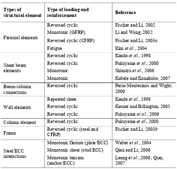
Table 2.4 Previous studies of various R/ECC structural elements…….... 27
Table 3.1 Detail of mix proportion of conventional concrete…………... 48
Table 3.2 Specification of PVA fibres (Nycon USA)………... 49
Table 3.3 Detail of mix proportion of engineered cementitious
composite……….….. 49
Table 3.4 Chemical properties of coal fly ash (ASTM C618)…………... 52
Table 3.5 Chemical compound contained in fly ash………. 52
Table 3.6 Tensile properties of reinforcements………. 55
Table 3.7 Target of drift ratio at each cycle……….. 60
Table 4.1 Specimen test data summary……….…… 67
Table 4.2 Analytical evaluation on the transfer mechanism of shear and
moment flexure based on design specifications……… 77
Table 4.3 Feasibility of strength degradation to each of test specimens... 83
Table 4.4 Evaluation of strong column/weak beam to each of test
specimens……….. 85
Table 4.5 Ratio of lateral resistance and nominal strength for the
evaluation of initial stiffness for all test specimens……...…… 86
Table 4.6 Adequacy of stiffness degradation of all test specimens……... 89
Table 4.7 Ratio of actual and ideal energy dissipation of all test
specimens………... 92
Table 5.1 Summary of scale factors for reinforced concrete true model... 139
Table 5.2 Ratio of maximum load capacity of prototype over half-scale
LIST OF NOTATIONS
λ = Overstrength factor for the test column
µΔ = Displacement ductility
Δu = Displacement at ultimate
Fexp = Lateral load obtained from
Mu = The unbalanced moment
Jc = Section property analogous
to the polar moment of
f'c = Concrete compressive
strength
ft = Designed tensile yield
strength
b0 = Peripheral length to critical
section
Mf = Flexural moment capacity
bo = Critical perimeter of slab
f'c = Concrete compressive
Fmax = Lateral load at peak point
Fexp = Lateral resistance
Mpr = Probable moment
φ = Strength reduction factor
Cd = Amplification factor
h = Column height
FLDR = The limiting initial drift
ratio
Mn = Nominal moment capacity
Ko = Initial lateral stiffness
K’ = Lateral stiffness at 3.5% drift ratio
En = Actual energy dissipation in
n increment of drift ratio
fcm = Mean compressive strength
of concrete obtained from test
εc1 = Strait at peak point
εcu1 = Nominal ultimate strain
εcuD = Concrete strain at point D
εcuE = Concrete strain at point E
εcuF = Concrete strain at point F
fcu1 = Concrete compressive
stress at ultimate point
fcuD = Concrete compressive
stress at point D
fcuE = Concrete compressive
stress at point E
fcuF = Concrete compressive
stress at point F
εcr = Concrete strain cracking
σb0 = Biaxial compressive
σc0 = Uniaxial compressive
strength
ε = Flow potential eccentricity K = Deviatoric invariant ratio
Ψ = Dilation angle
υ = Viscosity parameter
dc = Compression damage
dt = Tension damage
σtrue = True uniaxial tensile stress
of steel
εtrue = True strain of steel
εnom = Nominal strain of steel
εpl = Plastic strain of steel
ΔP = Small load increment K0 = Structure’s tangent stiffness
u0 = Initial displacement
configuration
ca = Displacement correction for
the structure
ua = Updated displacement
configuration
a = Designated equilibrium
point
b = New equilibrium point
cb = New displacement
correction for the structure
ub = New updated displacement
CHAPTER 1
INTRODUCTION
1.1. Background
Many laboratory and analytical studies have been carried out over the past
decades to improve the response of reinforced concrete structures under seismic
loading. Regarding the prior studies, the majority has been done primarily on
relatively new type reinforced concrete members, with the design not only consider
on improving the structural performance but also how to construct the more
economical system in the long run. It is worth mentioning that earthquake action is
a displacement oriented in nature whereby the forces acting on the structure are
controlled by strength and stiffness. In such situation, if the strength and stiffness
of service condition are insufficient, the structure will be prone to govern excessive
deformation which will also be followed by a major crack propagation.
To date the development of reinforced concrete structure has drawn upon
many alternatives to build in the cost-effective system. One of such is flat slab
system which offers modest design, flexibility in architecture, more spacious room
area due to the absence of beam members, and fast construction time (Erberik and
Elnashai, 2004). In addition, flat slab structural system also has high occupancy rate
and allows to add a number of floors in the highly restricted area (Robertson et al.,
2002). Since this class of structure has gained popularity among engineers, flat slab
structure has been established in various types (e.g. simple flat plate, flat slab with
drop panels, flat slab with column heads, etc.). Regardless of above advantages, the
seismic behaviour of flat slab structure, however, still becomes a profound
consideration. If the design of structure is not considered properly, the flat slab
structure is more prone to encounter progressive collapse when subjected to high
unbalanced moments and uniform shear forces. In such situation, the prominence
of local failure in some structural members will propagate vastly towards other
members thereby leading to catastrophe. Although it is considered as a low
probability phenomenon, the adverse effect of the damage can cause accidents and
In general, there are two types of failures that must be accounted for in the
design of flat slabs (viz, flexure and shear). Flexural failure is characterised by an
inclined crack perpendicular to loading direction which extends towards the entire
width of the slab, whereas slab failing in shear exhibits an inclined crack of 20-45
degrees to the horizontal that surrounds the perimeter of the column, creating a
failure surface that resembles a truncated pyramid. This failure is commonly
referred to as punching shear as the column appears to punch through the slab.
Punching shear failure is typically brittle and results in a nearly complete loss of
shear capacity, leading to progressive collapse to an entire floor, either with little
or without any warning.
The collapse of flat slab building, in reality, is perhaps the best example to
date to demonstrate the importance of preventing progressive failure. Several cases
of flat slab structure which were indicated by the brittle punching shear failure
occurred at L’Ambiance Plaza in Connecticut 1987 (Heger 1991), Commonwealth
Avenue in Massachusetts 1971, Skyline Plaza in Virgin Island 1973, and Harbour
Cay Condominium Building in Florida in 1981 (King and Dalatte, 2004). Other
similar reported cases also took place in Mexico 1985, where 91 buildings collapsed
severely due to the seismic events, and also 40 buildings were heavily damaged
(Megally and Ghali, 2000).
Upon the past incidents, a deep consideration to limit the number of
parameters in design has been taken into account. Design specification such as ACI
318-14 has determined the required limitations to design and calculate the punching
shear capacity in the critical section of the slab-column connection. In addition to
ACI 318-14, ASCE/SEI 7-10 has also limited the use of flat slab structure into
specific requirements. In moderate or high seismic regions, the addition of more
rigid members such as shear walls or external moment resisting beams is inevitable
in order to provide sufficient lateral load resistance. Although flat slab frames are
not designed to contribute the major lateral resistance, they still must demonstrate
sufficient strength, stiffness, and ductility to support gravity loads while undergoing
lateral displacements during the seismic event. With regard to its structural
response, seismic-induced lateral displacement mostly generates unbalanced
concentration in the critical region of the slab. Due to gravity load, uniform shear
stress also forms and sums up the stress from unbalanced moment thereby causing
the slab to undergo high shear stress. If the shear capacity is inadequate, the brittle
punching failure may occur (Dovich and Wight, 2005).
To deal with the fragility of the flat slab, there has been extensive research
carried out to provide in-depth insights into the full behaviour of slab-column
connection. For example, the utilisation of web reinforcements in the slab along the
critical perimeter. Robertson et al. (2002) studied the response of slab-column
connections subjected to lateral cyclic loading with the use of three distinct shear
reinforcements: closed stirrups, one-leg stirrups, and shear studs. It was shown that
web reinforcements could improve the lateral drift capacity up to 8.0% prior to
punching failure. During the observation, it was evident that the failure was in the
flexural mode, causing the stirrups did not achieve the ultimate capacity. Gunadi et
al. (2012) investigated the similar experiment by proposing the modification of
shear stud configuration in the form of stud rails. The results highlighted the initial
flexural cracks led to decrease in initial stiffness. However, it could effectively
show the improvement in energy dissipation.
Another alternative was also considered by employing drop panel as local
thickening (ACI 352.1R-89). Drop panel works effectively to reduce the negative
moment in the slab-column joint and also increases the stiffness which can reduce
the excessive lateral deformation. In addition to that, drop panel is used to improve
the shear capacity of the structural member significantly even though it still
generates brittle failure (Megally and Ghali, 2000). An experimental study
conducted by Prawatwong et al. (2008) has confirmed the influence of drop panel
in the behavioural response of the slab-column connections. In their experiments,
interior slab-column connections with and without drop panel members were
constructed. The study also included the utilisation of post-tensioned system to
enable the sufficient response to resist the cyclic lateral loading. It was shown that
punching shear was not yet to occur in the specimen with drop panel up to 4.0%
drift cycle but rather experienced at the drift ratio of 6.0%. On the contrary, the
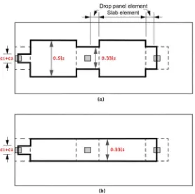
In addition to the above alternatives, the use of fibre-reinforced concrete was
also proposed to study the behaviour of slab-column connections. McHarg et al.
(2002) investigated the usage of steel fibres combined with high longitudinal
reinforcement ratio adjacent to the column. This research was focused on the
performance of the slab-column connection subjected to gravity loading. Steel
fibres with the volume fraction of 0.5% were given in distance of 500 mm from
column face, or it was equal to 3.3 times of the slab thickness. The results exposed
the improvement in terms of strength over the punching shear. The increase of
ductility was also evident and furthermore, crack widths were relatively small
during service condition. While there seems to be a number of methods for
improving the way in which the structure behaves, the results have not been able to
trigger the changes in any design code. Therefore, further relevant studies are
necessary in order to fully compromise the fragility of flat slab structure as well as
to exploit the predominance in other types of materials.
The present study is focused on the improvement of slab-column connection
behaviour under gravity and cyclic lateral load. Drop panel is proposed herein as it
gives a promising response in terms of providing sufficient lateral stiffness. The
main novelty of this research lies in the use of cement-based fibrous material,
termed as engineered cementitious composite (ECC). This type of material is
preferred due to its capability of avoiding brittle damage as well as offering the
good performance. Since the complex response of slab-column connection occurs
within the critical perimeter, the ECC material is only considered to be cast within
the local thickening, or in this case at the drop panel element.
This study is among the first to use ECC material for investigating the
behaviour of structural connections. The underlying reason for selecting the ECC
material is highly driven by its ability to exhibit high tensile ductility in the form of
pseudo-strain hardening response (Sahmaran and Li, 2008). In addition to that, it is
also known that polyvinyl alcohol (PVA) fibres offer the important role of
increasing the behavioural response in order to withstand shear and flexural stresses
(Li, 2002). In general, the tensile stress-strain response of ECC material generates
strain hardening behaviour with strain approximately ranging between 3-5% prior
with tensile strain normally up to 0.01% (Tambusay et al., 2017). It should also be
noted that the tensile response of ECC material can possibly go beyond that,
depending on the fibres positions inside the matrix and proper mixing procedure.
Aside from this, ECC material also demonstrates multiple yet closely-spaced micro
cracks with cracks width under 100 µm prior to fibres rupture.
Another aspect which strengthens this hypothesis in relation to the material
selection is basically based on the experimental results brought by Fukuyama et al.
(2000). The experiment was concerned about the response of beam-column joint
with or without the use of ECC material as the specimens were subjected to lateral
cyclic loading. The results indicated the increase of energy dissipation as well as
the damage tolerance at the end of the loading course. Additionally, brittle failure
was prevented, leading to the more ductile structure. It was also observed that bond
splitting phenomenon did not occur in the specimen with ECC material. Based on
above justifications, the use of ECC material in slab-column connection can
potentially be applied to upgrade the structural the structural response. To
demonstrate the applicability of ECC, the present work focuses on the test of
slab-column connections under gravity and cyclic lateral load. The results from this
study are expected to contribute to creating the sustainable civilisation in the future.
1.2. Research Significance
It is inevitable that the fragility of the flat slab has led to structural collapses
in the past seismic events. Although there seems to be a number of studies
concerning to this issue, the results still have not been able to trigger the
modifications in any design code. Facts on the ground also show that the current
flat slab structure still has poor initial stiffness and significant stiffness degradation.
In addition to that, brittle punching shear failure occurred in the connections also
indicates a relatively small lateral drift capacity and low energy dissipation.
Considering all the above, the main significance of this study lies on the utilisation
of engineered cementitious composite material that could be further used as a
potential alternative to improve the behaviour of the flat slab as an earthquake proof
study is expected to result in the better behavioural response at the connections of
flat slab system.
1.3. Research Objectives
The aim of this study is to analyse the behaviour of slab-column connection
due to combined constant gravity and reversed lateral load. Since a new type of
cement-based material, otherwise termed as ECC, is proposed, it is anticipated to
exploit the potency of ECC to result in the more ductile response with less damage.
Aside from using conventional web reinforcement in the slab, this study adopts an
additional member of what is called as drop panel. Slab flexural reinforcements,
either longitudinal or transversal steel, are designed with low ratio and are
positioned continuously to the column. The following specific objectives of this
study are:
1. To investigate the hysteretic response of slab-column connections through an
experimental program and finite element analysis.
2. To provide insights into the progression of cracks during the course of
loading.
3. To obtain the relation of drift capacity due to the influence of gravity shear
ratio on the slab.
4. To evaluate the acceptance criteria of the slab-column connections based on
ACI 374.1-05 as an earthquake proof and resistant structure with particular
focusing on the initial stiffness, stiffness degradation, strong column/weak
beam, strength degradation, and energy dissipation.
5. To facilitate direct information regarding the flexural strain gauge readings
from the slab reinforcing steel throughout the loading process.
6. To perform the nonlinear finite element analysis as a means to verify the
experimental results.
7. To provide a better picture regarding the distribution of principal stress
alongside the slab and diagonal compression strut at the joint with the value
8. To evaluate the performance of slab-column connections in dissipating the
earthquake energy through the visual observation from the length of plastic
hinge zone.
1.4. Scope of Research
The present work involves experimental investigation and numerical analysis
to study the behaviour of slab-column connections using ECC material and drop
panel member. By considering the probability of work in the laboratory as well as
making this research more focused, a number of limitations are given as follows:
1. Specimens are half-scale representation of interior slab-column connections
taken as subassembly system in a prototype of flat slab structure using the
dual system.
2. Specimens are tested under constant gravity load and uniaxial cyclic lateral
load in the form of displacement controlled. The loading protocol is in
accordance with ACI 374.2R-13. The biaxial load is not considered in the
loading protocol.
3. Test specimens are subjected to cyclic lateral load starting from the linear
elastic to nonlinear response with minimum expected drift ratio of 3.5%.
4. The gravity load is applied using prestressing technique, whereas the cyclic
lateral load is applied to the specimens using automated cyclic hydraulic
actuator with the displacement being increased not less than one and
one-quarter times, and not more than one and one-half times of the previous
displacement. The load is recorded using a load cell mounted on the hydraulic
actuator, while the horizontal displacement at column tip is recorded using
200-mm linear variable displacement transducer and is positioned alongside
the stroke of the actuator. All the data are collected automatically by the data
acquisition system.
5. Strains of slab reinforcements are recorded by strain gauges throughout the
course of testing with the data being transmitted using the data logger.
6. During testing, the crack pattern is observed on the top and bottom surface of
7. 3D nonlinear finite element analysis using ABAQUS is performed by
assuming the interaction between concrete and reinforcing steel to be
perfectly bonded in order to avoid challenging computation time during the
iteration process caused by nodal slip due to bond loses.
8. In finite element analysis, the relationship of stress-strain of ECC under
compression is assumed to fit the constitutive modelling of conventional
concrete.
1.5. Hypothesis Adopted
The work described in this thesis examines the study on the behaviour of
slab-column connection tested under gravity and cyclic lateral load. This research has
been directed towards the development of engineered cementitious composite
material as a replacement of conventional concrete as well as the utilisation of drop
panel member to improve the behaviour of above structure. This present work is
based on the assumption that in a typical design of flat slab frames, the slab-column
connections are considered to carry gravity load, and they are not intended to
contribute to lateral resistance. In such situation, the plastic hinge mechanisms are
anticipated to merely occur in rigid members such as shear walls (see Figure 1.1).
In general, when considering the design of reinforced concrete structure as a
dual system, the proportion of stiffness in elastic condition during the earthquake
can be determined in such a way, for example, 85% of earthquake forces are
transferred to the shear wall, while the remaining forces are transferred to frames.
Additionally, in terms of strength, frames should at least be able to carry not less
than 25% of earthquake forces (SNI 1726:2012; ASCE/SEI 7-10). This is to ensure
that while shear wall has already failed, frames still have reserved capacity to
withstand the earthquake forces. In other words, this is also called as second
defence mechanism where plastic hinge mechanisms are expected to occur within
the frames thereby allowing the structure to withstand inelastic deformation due to
the earthquake.
Although the failure pattern seems to be tangible, however, it is of importance
to note that earthquake is regarded as unforeseen loading conditions, meaning the
magnitude of seismic forces are unpredictable and they could have been higher than
that of expected in the calculation. Given this fact, if the slab-column connections
are not adequately designed to carry such immense forces, the punching shear
stress, indicated as brittle nature of concrete, may be the case which may also trigger
the likelihood of flat slab structure to govern the progressive collapse. When
considering the use of engineered cementitious composite material incorporated by
addition of drop panel member, it is anticipated that the behavioural response of
slab-column connection can be improved thereby permitting the possibility of the
slab-column frames to withstand earthquake forces. In such condition, the plastic
hinge mechanisms of the slab-column connections occur due to moment flexure
(see Figure 1.2). As a stepping stone toward achieving this goal, this study may
offer the probability of flat slab structure to be classified as earthquake proof and
CHAPTER 2
LITERATURE REVIEW
2.1. Flat Slab Structural System
Flat slab system shown in Figure 2.1 is a form of floor system in a reinforced
concrete building that offers prospective benefits over the conventional reinforced
moment-resisting frames (Erberik and Elnashai, 2004). The dominant dissimilarity
between the flat slab and other types of building lies in its type which only consists
of a monolithic structural component in the form of the slab, column, and
slab-column connection as its primary members.
As the structure does not employ any beam member, the fast construction
time and more economical rate become the major points for offering the good
alternative. However, regarding the structural response along the joints, a more
complex behaviour is essentially inevitable. It is indicated by the punching shear
phenomenon, causing the shear stress dominated the internal mechanism at the joint
location following the prominent drop in strength. In addition, the uniform shear
stress due to gravity load is one of the factors that may trigger the punching shear
failure in the connection (Bompa, 2011).
Flat slab structure is known as a two-way slab system according to SNI
2847:2013 and ACI 318-14. In the majority of building construction, flat slab
structure has a few variations including the flat plate with or without web
reinforcements, flat slab with drop panel or shear capital, and so on. Early design
specifications adopted by the American Concrete Institute was based on a report by
the Joint Committee of 1924. It was discussed to give the recommendation with
regard to the shear stress calculation and the allowable shear stress.
Based on the previous studies, the fragility of flat slab system is caused by
the combination of gravity and lateral loads. When flat slab structure is subjected
to lateral loading, the unbalanced moment will deliver the significant stresses in the
critical area of the connections and also the uniform shear forces from gravity loads
will sum up the local shear stresses (Gunadi et al., 2012). At this point, it is
evidently true that gravity loading can decrease drift capacity of slab-column
connections (Megally and Ghali, 2000) as well as decrease the initial stiffness
(Robertson et al., 2000), ductility (Pan and Moehle, 1992), and load-carrying
capacity (Robertson and Durrani, 1992). Since the general behavioural response
shows the tendency of weaknesses, design codes like SNI 2847:2013 and ACI
318-14 categorise flat slab system into the intermediate moment-resisting frame. When
it is built in the low or intermediate seismic regions, the single system is allowed.
On the other hand, when it is designed in the high seismic regions, the use of a dual
system with the contribution of shear walls is necessarily important. In reference to
previous statements, it is also clear that design specification does not allow to
design the flat slab structure in the level of special moment resisting frame whether
using single or dual system (ASCE/SEI 7-10). This can obviously cause the
non-efficiency in terms of advancing the sustainable construction related to high-rise
building constructions.
2.2. Mechanics of Slab-Column Connection
The slab-column connection shown in Figure 2.2 is defined as a joint which
is located in the part of the column within the depth of the slab including drop panel
and having plan dimensions equal to those of the column at the intersection between
the column and the bottom surface of the slab or drop panel (ACI 352.1R-89). In
flat slab structure, punching shear failure is most likely to occur around the slab
adjacent to the column face. This phenomenon inclines to take place because
structural members do not have sufficient strength when the columns give dominant
punching action. Furthermore, the region of slab-column connection presented in
Figure 2.3 is described of having the tendency of punching shear behaviour. Lateral
deformation occurred during the course of loading can result in moment and shear
at the joint while additionally, gravity load can also contribute to give significant
uniform stress at the similar location (Jirsa, 2009).
ACI 318-14 also outlines that load transfer transpired along the connection of
the critical perimeter involves shear forces Vg and unbalanced moments Mu. The
shear forces at the slab-column connections are affected by the transfer of shear
stresses uniformly in the area of the critical section near to column face as illustrated
in Figure 2.4. Furthermore, unbalanced moments are triggered due to the influence
of lateral load, resulting in two mechanisms (ACI 318-14). In this case, a fraction
of the unbalanced moment given by γfMu must be considered to be transferred by
flexure within an effective slab width between lines that are one and one-half slab
or drop panel thickness (1.5h) outside opposite faces of the column (ACI 318-14).
On the other hand, a fraction of unbalanced moment known by γvMu must be
Figure 2.4 Critical section (perimeter) of slab-column connection.
Figure 2.5 Transfer of uniform gravity load unbalanced moment within the
transferred by shear at the critical section of the slab-column connection. Figure
2.5 describes the transfer mechanisms of uniform shear stresses caused by gravity
loading and unbalanced moments at the critical perimeter. It is indicated that the
combined shear stresses are obtained from the linear summation between these two
factors. In the overall situation, transfer scheme of moment and shear in slab and
column during the loading course is illustrated in Figure 2.6.
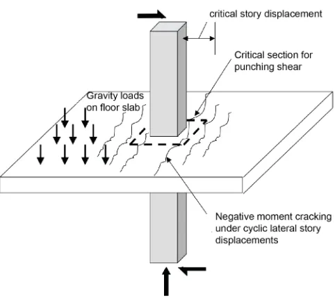
2.3. Failure Mode of Slab-Column Connection
Failure in flat slab structure is caused by the complex behaviour as a result of
the unbalanced moment and shear transfer mechanism in the connections due to
combined gravity and lateral loads (Shah, 2005). During the seismic event, the
unbalanced moment can result in significant eccentric shear stress in the slab area
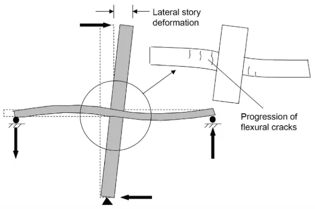
(Megally and Ghali, 2000). Presented in Figure 2.7 is the illustration of connection
response due to lateral loading applied in the column tip. It is shown that during the
loading sequence in the positive direction, flexural cracks start to appear in the area
of negative moment indicated by the condition when the top fibre of stress diagram
in a reinforced concrete is being pulled. At the same time, other cracks also start to
Figure 2.6 Schematic model for shear and moment transfer of slab-column
develop at the bottom of the slab in positive moment across the loading point. As
the loading is reversely alternated, the cracks appear in the same condition (Jirsa,
2009). At this point, the number of cracks and positive moment capacity in the
opposite direction exhibit depending on the ratio of bottom longitudinal
reinforcements. As having such compound behavioural response, it may lead to the
vulnerability on resisting a number of applied loads causing the severe damage,
termed as progressive collapse (Tegos and Tsonos, 1996).
2.4. General Setups of Slab-Column Connections Tested under Gravity and
Lateral Loading
There has been extensive research carried out to give a better understanding
in regard to the behaviour of slab-column connections under combined gravity and
reversed cyclic lateral load. A variety of testing configurations has also been
commissioned by different researchers. For convenience, most tests have usually
been done by implementing the subassembly techniques referred to the prototype
of the building. In addition to that, a reasonable assumption for determining
boundary conditions of the tested specimens has also been considered. For slab
supports, simple supports along the slab edges are mounted to simulate a point of
contra-flexure at mid-span in the slab. Also, simple support pinned connection at
the base ends is also used to generate an inflection point in the column at mid height.
While there seems to be convenient to proceed this method, however, a major
challenge in these test lies on how to apply and sustain a constant gravity loading
throughout the test. Several approaches have been proposed to overcome this
challenge. One of such is by hanging the portable concrete blocks to provide the
constant superimposed dead load. However, this method limited the researchers to
testing under very low or high gravity shear ratio. Another test variable that has
ranged widely is the influence of flexural reinforcement ratio. Some researchers
tend to use the overly amount of flexural reinforcements with the ratio over 1% to
force the punching shear failure. This is associated with the over-reinforced section
whereby concrete would crush prior to the yielding of flexural reinforcements.
Further explanations regarding the effect of flexural reinforcement ratio are
discussed in the following section.
2.5. Influence of Flexural Reinforcement Ratio
Flexural reinforcements on the slab are necessarily used in the column strip
to withstand the gravity load acting on the structural member. Although they are
designed to sustain the flexural moment, the increase in ratio can obviously affect
the punching shear capacity of the connection and the lateral stiffness significantly
(Tian et al. 2008). As stated in SNI 2847:2013, slab effective width is a part of
column strip that is also designed to carry the unbalanced moment flexure. In other
words, the flexural reinforcements within the effective width of the slab are
designed to strongly carry the fraction of the flexural moment with strength shall
not be less than half of the reinforcements in the column strip or it can be given as
0.375ρb.
A few of studies have been carried out related to the effect of flexural
reinforcement ratio in the slab. Tian et al. (2008) were among the first to
demonstrate the significant role on the influence of flexural reinforcement ratio in
relation to the behaviour of slab-column connections. This study focused on the
effect of flexural reinforcement ratios of 0.5% and 1.0% within the effective width
remained elastic under lateral loading. An experimental investigation was done
with five large-scale specimens. The specimens were loaded with respect to gravity
and lateral load. The results highlighted that punching failure of connections with
low reinforcement ratio was not induced by reaching the critical shear stress under
gravity and lateral load. The typical failure was more interpreted as shear
deformation-driven shear failure occurred when the inclined cracks were exhausted
which could be attributed to the concrete splitting across a plane. In contrast, as the
reinforcement ratio increased, connection punching capacity and lateral stiffness
increased significantly. At 1.25% drift level, punching shear failure was introduced
without affecting the capacity to carry the constant gravity load. However, it might
not be the case since ratio was limited up to 1.0%.
In the article written by Muttoni (2008), Kinnunen and Nylander (1960)
studied the influence of varying ratios of slab flexural reinforcement in slab-column
connections with regard to their punching shear capacity. The results highlighted
these following dictations:
(i) For low reinforcement ratio (ρ = 0.5%), it was shown that structure behaved
in the more ductile manner where all the flexural reinforcement bars had
yielded. In this particular case, it was confirmed that the strength of slab was
limited by flexural capacity and punching shear occurred in a certain
condition where large inelastic deformation occurred.
(ii) For intermediate reinforcement ratio (ρ = 1.0%), some of the flexural
reinforcement bars had yielded in the region nearby the column. However,
punching shear was stricken before all the reinforcement bars yielded, owing
to the fact that the strength in the slab was smaller than its flexural capacity.
(iii) High reinforcement ratio (ρ = 2.1%), it was evident that punching shear
occurred in a condition where all flexural reinforcement bars were yet to
yield. Moreover, the response was indicated by a very brittle behaviour. From
this inclination, it was confirmed that the strength if the slab was way too
small compared to its flexural capacity.
From these relevant research, it can be concluded that the increase in flexural
reinforcement ratio can somehow increase the punching shear capacity but by
which can associate by the crushing of concrete prior to the yield of reinforcement
bars.
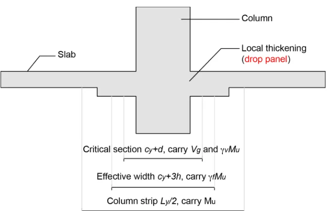
2.6. The Use of Drop Panel in Flat Slab Structure
In general, drop panel is used to reduce the negative moment in the joint over
the slab as well as increase the stiffness to lessen the lateral deformation caused by
the applied loading (ACI 318-14). Drop panel is also used to thicken the slab in the
joint towards the slab effective width in order to give sufficient shear strength for
avoiding the early punching shear failure (Sathawane and Deothale, 2012). Since
conventional flat slab structure is not designed to have web reinforcements in the
slab, drop panel used to be the only option of providing the better behavioural
response by putting more thickness in the joint. There has been a few research
focusing on the behaviour of flat slab structure by using the drop panel as local
thickening member of the joint. These studies designed drop panel elements based
on the recommendation given by ACI specification. To give a better picture of drop
panel, Figure 2.8 illustrates how drop panels are applied to the flat slab structure.
ACI 318-14 outlines the limitation in design whereby drop panel is used to
reduce the amount of negative moment over the column of a flat slab, the size of
drop panel shall be in accordance with the following:
(i) Drop panel shall extend in each direction from centreline of support a distance
not less than one-sixth the span length measured from centre-to-centre of
supports in that direction.
(ii) Projection of drop panel below the slab shall be at least one-quarter the slab
thickness beyond the drop.
(iii) In computing required slab reinforcement, the thickness of drop panel below
the slab shall not be assumed greater than one-quarter the distance from the
edge of drop panel to edge of the column.
Given that ACI 318-14 also mentions the modification of slab in thickness of the
critical section must consider the assessment of shear strength.
Designing drop panel can be done using direct design method arranged by
ACI 318-14 or SNI 2847:2013. However, it is important to note that there are
several limitations has been outlined as follows:
(i) There shall be a minimum of three continuous spans in each direction.
(ii) Panels shall be rectangular, with a ratio of longer to shorter span
centre-to-centre of supports within a panel not greater than 2.
(iii) Successive span lengths centre-to-centre of supports in each direction shall
not differ by more than one-third the longer span.
(iv) Offset of columns by a maximum of 10% of the span (in direction of offset)
from either axis between centrelines of successive columns shall be
permitted.
(v) All loads shall be due to gravity only and uniformly distributed over an entire
panel. The live load shall not exceed two times dead load.
Designing of flat slab structure can also be done by adopting the effective
beam width method. This method has been extensively used to predict the lateral
drift and amount of unbalanced moments in slab due to lateral load. Numerous
research showed that modification on drop panel dimension in the interior and
exterior can provide the increase in response significantly. Choi et al. (2001) were
among the first to study the coefficient of effective width for a larger span of
slab-column connections which was calculated using finite element programme tool.
This relevant study used the following fundamental assumptions to reckon the