EFFECT OF MULTI PASS HIGH ENERGY MILLING ON
MORPHOLOGY AND RHEOLOGICAL PROPERTIES OF CARBON
NANOTUBES
Nono Darsono
Research Center for Metallurgy and Material – LIPI, Building 470, Kawasan Puspiptek Serpong, Tangerang Selatan
E-mail : [email protected]
Masuk tanggal : 15-06-2014, revisi tanggal : 04-07-2014, diterima untuk diterbitkan tanggal : 18-07-2014
Abstract
EFFECT OF MULTI PASS HIGH ENERGY MILLING ON MORPHOLOGY AND RHEOLOGICAL PROPERTIES OF CARBON NANOTUBES. Multi pass high energy milling was utilized in order to cut and disperse carbon nanotubes (CNTs) suspension. The purpose is to maintain the crystallinity and suppress the damage. One until five passes gave increase in D- to G-band ratio which means increasing the damage, at the value range from 0.1 to 0.2. The ratio is still lower compare 2-hour high energy milling and 120-hour conventional ball milling, at the value of 0.5 – 0.3. The rheological properties was not altered dramatically. It is indicated that the milling only tears down the aggeregates into small fraction of entangled CNTs treads.
Keywords : Carbon nanotubes, High energy milling, D-to G-band ratio, Crystallinity, Rheological properties
Intisari
PENGARUH DARI MULTI PASS HIGH ENERGY MILLING TERHADAP SIFAT MORFOLOGI DAN REOLOGI PADA KARBON NANOTUBE. Multi pass high energy milling dilakukan untuk memotong dan mendispersikan suspensi carbon nanotubes (CNTs). Tujuan dilakukannya percobaan ini adalah mempertahankan kristalinitas dan mencegah kerusakan yang terjadi akibat milling. Hasil percobaan memperlihatkan proses milling 1 hingga 5 pass memberikan peningkatan terhadap rasio D- terhadap G-band, yang mengindikasikan telah terjadi kerusakan, direntang 0,1 sampai 0,2. Rasio ini lebih rendah dibandingkan dengan high energy milling selama 2 jam dan konvensional ball mill 120 jam yang memberikan rasio direntang 0,5 – 0,3. Sifat reologi tidak berubah secara dramatis. Hal ini mengindikasikan bahwa milling yang dilakukan hanya memecah aggregat menjadi fraksi kecil dari jaringan CNTs.
Kata kunci : Karbon nanotube, High energy mill, Rasio D- terhadap G-Band, Kristalinitas, Sifat reologi
INTRODUCTION
Since its discovery in 1991[1], carbon nanotubes (CNTs) have attracted attention in the field of conducting polymer and electronic appliance due to nanoscale structure, excellent electrical, thermal conductivities, chemical, and mechanical properties[2-5]. It also has the ability as a metal absorbance, as reported by Kabbashi
et al. [6]. However, CNTs have its limitations due to low dispersion properties. The high aspect ratio, high flexibility of the tube, and high van der waals forces between the thread made it severely entangled. Moreover, chemically
inert wall of CNTs exhibits a poor dispersibility and weak interaction with suspending media.
104 |Majalah Metalurgi, V 29.2.2014, ISSN 0126-3188/ 103-110
into individual manner. The loaded energy on the CNT by means of direct mechanical contact between CNT and milling media often made the CNT to shorten or decrease its crystallinity.
The surface modification methods are intended to improve the chemical properties of the outer surface of the CNTs. The method includes oxidation process by acid treatment, UV/ozone treatment, introduction of a surface-active agent, polymeric wrapping of CNT, or combination of several process. Those methods indeed also made damage on the structure of CNTs. Highly reacted
chemical will disturb the nature of π-bonds CNTs.
For electronic application, high crystallinity of CNT is required to get a good electrical property. In our previous research, CNTs was utilized as an electron emitter in field emission display (FED). We tried to cut and disperse CNTs using high energy milling on the MWNT after adding a commercial dispersant. The experimental result shows that high energy milling can be applied for many practical applications including paste preparation for FED. In the same time, the degree of crystallinity was also decreasing due to collision and impact forces between CNT and milling media. Therefore the present study investigated the rules of modified high energy milling in order to increase the effectiveness of high energy milling. At previous experimentation, continuous system with a very high rotor rotation per minutes (RPM) was utilized for milling process[15,17]. But in this paper
discontinuous system with low rotor RPM will be applied in order to suppress milling damages.
EXPERIMENTAL METHOD
Thin multi-walled carbon nanotubes (T-MWNTs) grown by catalytic CVD method (Dobong-CNT, Korea University, Korea) were used for this experiment. Slurry was prepared by adding 8 g of T-MWNTs into 400 g of ethanol to form slurry of 2 wt. % MWNTs with respect to the solvent content. This slurry was mixed by using ultrasonicator for 5 minutes. Milling process was performed by using high energy milling (MiniCer, Netzsch, Germany) at 600 rpm by adopting discontinuous circulation methods for 1, 2, 3, 4, and 5 milling pass. Furthermore, a small amount of sample was taken out for each pass for characterization. The rheological characteristics were measured at 20oC using a computer controlled cone-type viscometer (LVDV-II+, Brookfield, MA, USA) with CPE-52 spindle at various shear rates.
As-received CNT Characterization
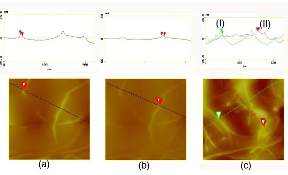
Effect of Multi…../ Nono Darsono | 105 Figure 1. 3-dimensional image of the tube
3-dimensional image of the tube was shown in Fig. 1. The profile image was represented by color. Brighter image indicates higher surface and darker means lower or based. Fig. 1 was converted into 2-dimensional image, as shown in Fig 2.
Figure 2. 2-dimensional images for the 3 different places
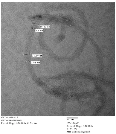
106 |Majalah Metalurgi, V 29.2.2014, ISSN 0126-3188/ 103-110 Figure 3. As-received carbon nanotubes acquaired
by TEM
Figure 3 shows a direct measurement by using TEM in magnification of 100,000 times. Measurement result indicates that the tube diameter is 10.75 nm. Direct measurement by using both AFM and TEM images shows a good agreement at 9
– 11 nm.
RESULTS AND DISCUSSION
Rheological Behavior of CNTs Suspension
Figure 4 shows rheological characteristic as a function of shear rates. It shows shear thinning behavior, as indicated by the decreasing of viscosity with the increasing of shear rates. In order to express this characteristic, power law model was used. Therefore, the viscosity curve in Figure 4 was fitted by power law model:
µ = m.
(1-n) (1)Where:
µ is the viscosity of the slurry,
m and n are model constants, and material can be devided in to three stages: 1. Breaking the agglomerate or entangled
material into small fraction.
2. Disentanglement of the CNT in to individual tubes.
3. Cutting of individual tubes.
Figure 4. Rheological change of CNT suspensions after several pass
Effect of Multi …../ Nono Darsono | 107 Its trend explained that disentanglement of
CNT was occurred after several milling pass.
Physical Morphology and Crystallinity Change After Milling
The destruction of the CNTs tread was inevitable due to physical impact and shearing during milling process. Figures 5 and 6 shows the morphology after several pass characterized using scanning electron microscope (SEM) and transmission electron microscope (TEM).
(a) (b)
(c) (d)
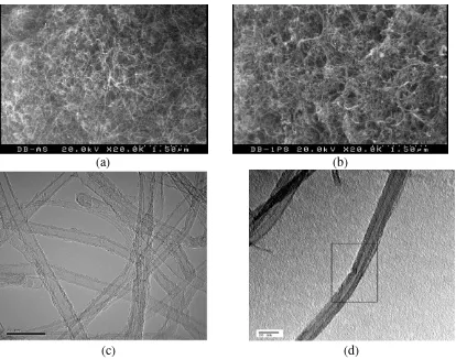
Figure 5. Comparison of morphology after high energy milling for 1 pass: (a) and (b) are SEM, (c) and (d) TEM Images (additional mark: please make the scale bar value larger)
A comparison images between Figures 5 (a) and (b) shows that high energy milling disentangles CNTs agglomerates into small fraction of CNTs aggregates or even individual of CNTs. As received CNT shows 2 graphene layers with approximately 9 – 10 nm of diameter as shown in Figure 5(c). The graphene layer was smooth and having small curved morphology on the surface indicating carbonaceous materials attached on the surface of tubes. High energy milled CNT as indicated in Figure 5(d) shows a groovie and kinked morphology on the outer surface indicating destruction of the outer
shell during milling. However, the tube shape was still preserved which means the high energy milling did not give full destruction on the CNTs.
Alternative method for characterizing the degree of damage is to use raman spectrofotometry. Figure 6 shows the Raman spectra profile. The G-band at 1585 cm-1 indicates the resonance of graphitic crystalline plane and D-band around 1286 cm-1 indicate the resonance of disorder plane of graphitic and carbonaceous materials attached on the CNTs [DD,ZZ]. The relative ratio intensity between D- and
108 |Majalah Metalurgi, V 29.2.2014, ISSN 0126-3188/ 103-110
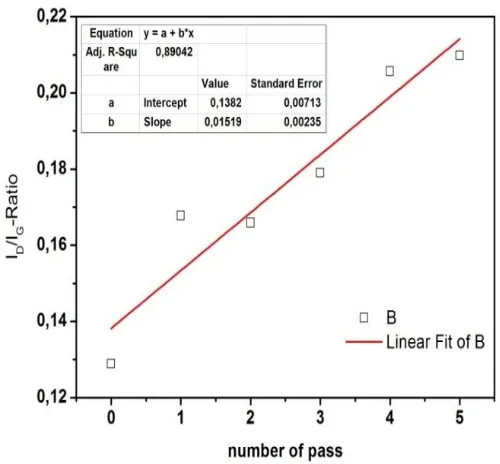
(Figure 7). The higher the D- to G-band intensity ratio resulted in higher damage. The relative ratio was increased linearly as the number of passing increased. As comparison with our previous result for more intense high energy milling such as 120 hours ball milling and 2 hours the degree, The D-to G-ratio are approximately 0.3 and 0.5, respectively
[15]
. Therefore, multipassed high energy milled sample shows higher crystallinity.
Figure 6. Raman spectra of CNTs suspension after 1 – 5 passed
Figure 7. Linear fit of raman spectra
CONCLUSION
Multi pass high energy milling was applied in order to break the agglomerates into more fine CNTs tubes without decreasing its crisytallinity. Nevertheless, the crystallinity of CNTs was decreased by increasing the number of pass . However, the degree of crystallinity is still higher in contrast to our previos study by using continously 2 hours high energy milling.
ACKNOWLEDGEMENT
Effect of Multi …../ Nono Darsono | 109 Ugarte D.. 1997. ,,Carbon Nanotubes Films: Electronic Properties and Their Application as Field Emitters”.
Zeitschrift für Phys. D Atoms, Mol. Clust., vol. 40, no. 1, pp. 418–420. [4] Fischer F. Du, J., and Winey K..
2005. ,,Effect of Nanotube Allignment on Percolation
Conductivity in Carbon
Nanotube/polymer Composites”.
Phys. Rev. B, vol. 72, no. 12, pp. 1–
oriented Carbon Nanotube
Microelectrode Array to Enhance The Sensitivity of Indoor Air Pollutants Capacitive Detection”.
Sensors Actuators B Chem., vol. 153, no. 1, pp. 103–109.
[6] Kabbashi N., Karim M. I. A., Saeed M. E., and Yaacob K. H. K. 2008. ,,Application of Carbon Nanotubes For Removal of Copper Ion From P. 2011. ,,Influence of Dry Grinding in a Ball Mill on The Length of Multiwalled Carbon Nanotubes and Their Dispersion and Percolation
Behaviour in Melt Mixed
Polycarbonate Composites”.
Compos. Sci. Technol., vol. 71, no. 8, pp. 1145–1153.
[9] Kim S. W., Kim T., Kim Y. S., Choi H. S., Lim H. J., Yang S. J., and Park C.R. 2011. ,,Surface Modifications for The Effective Dispersion of Cationic, Anionic and Non-ionic Multi-walled Carbon Nanotubes, Functionalised with Minimal Framework Damage, for Biomedical Application”, Biomaterials, vol. 35, no. 17, pp. 4729–4738.
110 |Majalah Metalurgi, V 29.2.2014, ISSN 0126-3188/ 103-110
Milling and Their Hydrogen Adsorption Behavior”. Carbon N. Y., vol. 41, no. 13, pp. 2527–2532. [14] Luo P., Wu H., and Morbidelli M.
2014. ,,Dispersion of Single-walled Carbon Nanotubes by Intense Turbulent Shear in Micro-channels”.
Carbon N. Y., vol. 68, no. 0, pp. 610–618.
[15] Darsono N., Yoon D.-H., and Kim J. 2008. ,,Milling and Dispersion of Multi-walled Carbon Nanotubes in Texanol,” Appl. Surf. Sci., vol. 254, no. 11, pp. 3412–3419.
[16] Olowojoba G., Sathyanarayana S., Caglar B., Kiss-Pataki B., Mikonsaari I., Hübner C., and Elsner P. 2013. ,,Influence of Process Parameters on The Morphology, Rheological and Dielectric Properties of Three-roll-milled Multiwalled
Carbon Nanotube/epoxy
Suspensions”. Polymer (Guildf)., vol. 54, no. 1, pp. 188–198.
[17] Darsono N., Yonathan P., Yoon D.-H., Kim J., and Kim Y.. 2008. ,,Dispersion and Field Emission Properties of Multi-walled Carbon Nanotubes by High-energy Milling”.